Embed Size (px)
Citation preview


DETECTING EFFICIENCY OF THE RESISTANCE-
CAPACITY COUPLED AMPLIFIERTO 6000 METERS
DISSERTATION
SUBMITTED TO THE BOARD OF UNIVERSITY STUDIES
OF THE JOHNS HOPKINS UNIVERSITY.
IN CONFORMITY WITH THE REQUIREMENTS FOR THEDEGREE OF DOCTOR OF PHILOSOPHY.
BY
W. G. BROMBACHER
BALTIMORE
1922


DETECTING EFFICIENCY OF THE RESISTANCE-
CAPACITY COUPLED AMPLIFIERTO 6000 METERS
DISSERTATION
SUBMITTED TO THE BOARD OF UNIVERSITY STUDIES
OF THE JOHNS HOPKINS UNIVERSITY.
IN CONFORMITY WITH THE REQUIREMENTS FOR THEDEGREE OF DOCTOR OF PHILOSOPHY.
BY
W. G. BROMBACHER
BALTIMORE
1922

<"*

[Reprinted from THE PHYSICAL REVIEW, S.S., Vol. XX., No. 5. November,
DETECTING EFFICIENCY OF THE RESISTANCE-CAPACITYCOUPLED AMPLIFIER TO 6,000 METERS.
BY W. G. BROMBACHER.
SYNOPSIS.
Detecting Efficiency and Current Amplification of the Resistance-capacity Coupled,
Two-tube Amplifier. Test of Hulburt's formula, giving a relation between detecting
efficiency and the constants of the tubes and circuits, has been extended to 6,000
meters. The detecting efficiency is defined as bo/A 2, where A and bo are the ampli-
tudes, respectively, of the input grid potential and of the rectified component of
the output plate current. It was found that (i) for any wave-length the relation
between 60 and A 2 is linear; (2) for constant wave-length, bo/A2 varied with the
coupling capacity in accordance with the formula within about 10 per cent., being
practically constant for capacities greater than 200 /z^ F; (3) for constant capacities,
bojA2 varied with wave-length for ranges 1,100 to 2,500 and 2,500 to 6,000 meters in
fair agreement with the theoretical curve. The current amplification, n = bo/Eg*,
where Eg is the amplitude of the potential impressed on the grid of the second
tube, was found to be independent of the wave-length to 6,000 meters.
Plate current of vacuum tube (Radiatron UV 201) was found to be sensitive to the
external temperature.
i . INTRODUCTORY.
The detecting efficiency of the, resistance-capacity coupled electron
tube amplifier has been discussed by E. O. Hulburt. 1 He derived a
formula which indicated the connection between it and the constants of
the electron tubes and the coupling circuits. His experiments showed
that the theoretical relation held in the region from 400 to 1,600 meters.
The detecting efficiency was defined by the relation lim -a ,
in whichA-+oA Z
A and 60 are the amplitudes, respectively, of the input grid potential
and of the rectified component of the output plate current.
Consider the high frequency amplifier of two tubes as shown in Fig. i .
1 PHYS. REV., 18, 165, 1921.
Fig. 1.
543906

1
[SECOND434 W. G. BROMBACHER. [SERIES.
For this type of amplifier Hulburt derived the following formula, subject
to the conditions that there be no rectification in the first tube and no
grid filament current in the second tube
gs)
in which ^4 is the amplitude of the radio frequency potential impressed
on the grid of the first tube, b is the rectified component of the resulting
radio frequency current in the plate circuit of the second tube; k is the
amplification constant of the first tube. r\ is the internal resistance of
the first tube from filament to plate. C5 is the filament-grid capacity of
the second tube. Resistances r% and r$ and capacity 4 are as shown
in Fig. i.
Let co/27r be the frequency of the impressed voltage.
Let
- =gi, o>C4
= Xt ,
ri
- =gi, wC5
= X6 .
r<i
i- =g3,
r
One term has not been defined, which is
n "Wwhere E Q is the amplitude of potential impressed on the grid of the
second tube, n does not depend on the frequency of the impressed
voltage. (See Fig. 6.)
Let
gigs x&f, = a,
Xi(g2 + gs) + Xbg 2= b.
Then, more accurately, the formula may be written
a(a + gig3) + b(b + x^ -+
It is to be noticed that this formula gives the detecting efficiency in terms

VoL.^XX. jDETECTING EFFICIENCY OF AMPLIFIER. 435
of the constants of the electron tubes and the coupling circuits. Also
Formula (i) is an approximation of (2), the use of which is justified under
obvious conditions.
The object of this paper is to make the experimental measurements
necessary in order to test Formula (i) for long wave-lengths, and to this
end measurements were made from 1,000 to 6,200 meters.
2. APPARATUS.
The apparatus consisted of a condenser potential divider, the amplifier
and a D'Arsonval galvanometer. The arrangement is essentially that
of Fig. i. The potential divider consisted of the coil L, the Weston
thermo-galvanometer T, and the condensers Ci, C2 and C3 . This appa-
ratus has been previously described by Hulburt and Breit. 1 The poten-
tial impressed on the grid of first tube may be found from
A ___"
C2 + CiC8 + C2C3)
in which I is the effective current measured by T. By coupling L to a
suitable electron tube generating set, unmodulated high-frequency voltage
of a small known amplitude and frequency was impressed on the grid of
the first tube. The high-resistance leak r$ was connected across C2 to
insure a definite value of the grid potential during the experiment.
The effect of r upon the impedance of C2 was negligible because C2 was
large (either .05, .1, or .2 MF) and the frequencies used were of the
order of io5.
The amplifier was a two-tube one with resistance capacity coupling.
The tubes were General Electric Company tubes, Radiatron type UV 201 ;
they were used with the filament current of .94 ampere and had a
common plate voltage supply of 52.3 volts. Separate storage cells
supplied each filament. The plate current was found to be sensitive to
external temperature changes, an effect explained, perhaps, by the
fluctuation in the amount of the absorbed gases in the glass walls of the
tubes. It was therefore found necessary to enclose the electron tubes in
covered cardboard tubes in order to keep their temperatures constant.
The plate battery was shunted by a 1.75 MF condenser C&. The re-
sistance r2 was 115 X io3 ohms and r3 was 360 X io3 ohms. The
resistances r,r2 and rs were non-inductive, being of the type described
by Hulburt.2 These were found to give satisfactory service. The value
of the resistance for high-frequency currents was assumed the same as
that measured with direct current.
1 PHYS. REV., 16, 274, 1920.2 Loc. cit.

436 W. C. BROMBACHER.
The change in the value of the rectified high-frequency component of
the plate current of the second tube of the amplifier, designated by b ,
was measured by a D'Arsonval galvanometer, G, Fig. I, connected
across a resistance r4 placed in the plate circuit. r4 was 60,000 ohms.
The galvanometer had a resistance of 9.0 ohms and a sensibility of
5.8 X io~8amperes per millimeter deflection on a scale 125 cms. distant.
PI and P2 , Fig. i, were potential dividers, PI serving to keep the plate
voltage at the desired value, and P2 to compensate for the potential drop
in the resistance r4 so that the galvanometer rested approximately at
zero. When the grid voltage of the first tube was changed, a deflection
of the galvanometer resulted which was proportional to the change in the
rectified high-frequency component of the output plate current.
It was important that the filament currents remain constant. Anychange in these currents resulted in a shift of the operating point of the
tubes. The electron tubes were seasoned before every series of readings
until a reasonably constant condition of filament current and electron
emission was reached. In order to eliminate the error due to the usual
slow drift of the galvanometer, the two zero readings were averaged. It
was found that the grid leak r gave a constant potential of nearly zero
on the grid of the first tube when its value was 246 X io3 ohms. This
value was not critical. For large values of rQ ,the value of the grid
potential shifted when it was necessary to vary the value of C3 . AKolster decremeter, calibrated by the Bureau of Standards, was used
to determine the wave-lengths of the high-frequency current.
3. VARIATION OF COUPLING CAPACITY.
The reading of the coupling condenser C4 was varied at each reading,
a number of input potentials were impressed on the grid of the first tube
and the corresponding galvanometer deflections were noted. From the
reading of T, the thermo-galvanometer, and a knowledge of the capacities
Ci, Cz and 3, the amplitude of the change of the input grid voltage Awas computed, using formula (3). Three sets of readings were taken,
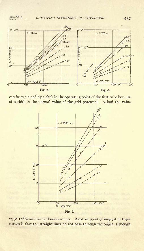
at wave-lengths 1016, 3070 and 6235 meters. The resulting curves
with b the ordinates and A z the abscissa, are shown in Figs. 2, 3 and 4.
It can be seen that for each value of C4 for all three wave-lengths the
b A z curves are straight lines. This fact has been established by a
large number of similar curves, not shown here. The curves for any one
wave-length are plotted from data taken with the potential divider
condensers C2 and C3 held constant. A change in the value of C*3 caused
the curve for any particular value of C4 to shift and also to change its
slope. This is shown in Fig. 3 by the curve marked 628'. This fact
VOL. XXNo. DETECTING EFFICIENCY OF AMPLIFIER. 437
ZOO 400 I0"!
feOO
Fig. 2. Fig. 3.
can be explained by a shift in the operating point of the first tube because
of a shift in the normal value of the grid potential. r had the value
20C
50 100 150 . 10'
Az - VOLTS2
Fig. 4.
13 X io5 ohms during these readings. Another point of interest in these
curves is that the straight lines do not pass through the origin, although

438 W. G. BROMBACHER. [SECOND[SERIES.
within the limit of experimental error they pass through a common
point on the A 2 axis. This seems to indicate a constant error in the
determination of A 2although a check up of the calibrations revealed no
differences large enough for compensation. It is also of interest to notice
that for each wave-length there is practically the same current range
(&o) but that there is a large range in the value of A 2 - for 1016 meters,
.006 to .015; for 3070 meters, .002 to .005 and for 6235 meters, .0006 to
.0015 volt2.
The main fact, however, remains that the straight lines were obtained,
as is predicted by formula (i).
In order to further test formula (i) the slopes of the curves corre-
sponding to each value of 4 were determined and then plotted against
values of C4 for each of the three wave-lengths as shown in Fig. 5. That
40
20
10'
3070
1016
.C4 .
200 400 MM F 600
Fig. 5.
is, experimental values of b /A2 are plotted against values of C4 . Then,
from formula (i) the theoretical value was computed. Values of the
constants not before given, r it the direct-current filament to plate re-
sistance of the first tube, was 60 X io3 ohms; C5 ,the filament-grid
capacity of the second tube, was 18 MMF. This was measured in its
socket and included the capacity of its lead wires, which were short,
however. As neither n or k were determined experimentally, the com-
puted curve was made to coincide with the experimental curve at C4

VOL. XX.No. 5.
DETECTING EFFICIENCY OF AMPLIFIER. 439
equal to 628 MMF. The computed curves are the broken lines. While
the agreement between the experimental and computed curve is not
exact, it is quite satisfactory, revealing no marked differences in behavior
for two of the wave-lengths considered, while for wave-length 3,070 m.
the agreement is good.
No change in the character of the computed curve was found whether
formula (2) or its approximation (i) was used.
4. VARIATION OF WAVE-LENGTH.
The coupling capacity C was kept at its maximum value of 628 MMF,ro, r 3 and r4 remained at their former values of 115 X io3
, 360 X io3 and
60 X io3 ohms. A series of readings were taken so that the variation
of detecting efficiency with wave-length could be determined. The
experimental results are given in the full line curve of Fig. 6.
80-
40.10"
0-o 2000 GOOOMETERS 4000
Fig. 6.
As the curve connecting the square of the input grid potential and
the rectified component of output plate current does not pass through
the origin, a series of readings was taken at each wave-length, a curve
drawn and the slope determined. This slope is bo/A2
. The experimental
curves just mentioned were straight lines within experimental error.
In order to keep the grid potential of the first tube constant for the
entire range of wave-lengths used, it was found necessary to fix its value
near zero, which was done by making TO equal 246 X io3 ohms. This
was tested by obtaining the deflection of the galvanometer when the
condenser C2 was short circuited, there being no high-frequency current
in the input circuits. This test was made when the condensers C\ and
Cs had values corresponding to the range of wave-lengths used. 2 was
0.2 MMF throughout the run.
The computed curve, shown dotted in Fig. 6, was made to agree with
the experimental curve in the neighborhood of 2900 meters. It was

44-O W. G. BROMBACHRR.
computed from formula (2), as the approximate formula (i) differed
with it over the range of wave-lengths computed.
The agreement of the two curves is substantial above 2,500 meters,
and, it is believed, would be even better, if the apparatus had been
used with better control over the grid potentials. The poor agreement
at lower wave-lengths is due to the difficulty of keeping conditions
constant for the entire range of observations. An unpublished curve,
detecting efficiency against wave-length, for the region between 2,500-
1,100 meters gives a straight line of about the same slope as the theoretical
curve. This is in agreement with the straight-line relation obtained by
Hulburt between 600-1,600 meters. Thus, the simple theory under-
lying Hulburt's formula is in agreement with experiments thus far made.
It is seen that the detecting efficiency at higher wave-lengths (lower
frequencies) becomes independent of the wave-length.
5. AMPLIFICATION.
It was necessary to test the independence of n with respect to wave-
length. By definition
where b is the rectified component of the output plate current and E g
is the amplitude of the potential variation on the grid of the second tube.
In order to measure n the input voltage was impressed directly on the
second tube, the first tube being disconnected, and the output plate
current was found for a series of wave-lengths. As before, sufficient
observations were made for each wave-length so that a curve could be
drawn and the slope determined. The slope was bo/E g2
. The curves
so determined were straight lines, n was found to be sensibly constant
for all wave-lengths as is shown in Curve 3, Fig. 6.
If the ordinate of Curve I be divided by the ordihate of Curve 3 at
the same wave-length, both of Fig. 6, the quotient is the amplification
of the current obtained by the use of the amplifying electron tube.
That is, the quotient gives the number of times the rectified component
of the plate current, b,is increased by the use of two tubes instead of
one. The quotients, or current amplifications, are the ordinates on the
right margin of Fig. 6. If telephones are used the sound intensity
amplification is proportional to the square of these numbers.
This problem was suggested to me by Dr. E. O. Hulburt, now at the
State University of Iowa, who derived the formula underlying the
investigation.
JOHNS HOPKINS UNIVERSITY,
June, 1922.

BIOGRAPHICAL NOTE.
William George Brombacher, son of Henry and Elizabeth (Case)
Brombacher, was born in Cleveland, Ohio, February 23, 1891. Hereceived his early education in Chicago High Schools. In 1915 he re-
ceived the degree of Bachelor of Arts from Lake Forest College with
Shield Honors and in 1917 the degree of Master of Arts from the same
college. The year 1918 was spent in the United States Army, stationed
at the Bureau of Standards. Upon leaving the army joined the Bureau
of Standards staff.
In the fall of 1919 he was entered at the Johns Hopkins Universityas a graduate student and as an instructor in Physics. He followed the
courses of Professors Ames, Wood, and Pfund in Physics, Professor
Murnaghan in mathematics and Professor Reid in Geophysics.


UNIVEESITY OF CALIFOENIA LIBEAEY,
BEEKELEY
THIS BOOK IS DUE ON THE LAST DATESTAMPED BELOW
Mjg'^sssSgS'fcSSS' _ f _ _- lvn *TOT* T.nP SlXtU U.i*J J_UW*."
75m-7,'30
_J

PhotomountPamphletBinder
Gaylord Bros.Makers
Syracuse, N. Y.FAT. JAN 21, 1903
439
UNIVERSITY OF CALIFORNIA LIBRARY

'


![Detecting and Exploiting Vulnerability in ActiveX Controlsfarsi]-detecting-and-exploiting... · Detecting and Exploiting Vulnerability in ActiveX Controls Shahriyar Jalayeri (Snake)](https://img.dokumen.tips/doc/110x75/5d142cfd88c993f1238cf355/detecting-and-exploiting-vulnerability-in-activex-controls-farsi-detecting-and-exploiting.jpg)


![Detecting Carbon Monoxide Poisoning Detecting Carbon ...2].pdf · Detecting Carbon Monoxide Poisoning Detecting Carbon Monoxide Poisoning. Detecting Carbon Monoxide Poisoning C arbon](https://img.dokumen.tips/doc/110x75/5f551747b859172cd56bb119/detecting-carbon-monoxide-poisoning-detecting-carbon-2pdf-detecting-carbon.jpg)


![Detecting Carbon Monoxide Poisoning Detecting Carbon ...2].pdf · Detecting Carbon Monoxide Poisoning Detecting Carbon Monoxide Poisoning. ... the patient’s SpO2 when he noticed](https://img.dokumen.tips/doc/110x75/5a78e09b7f8b9a21538eab58/detecting-carbon-monoxide-poisoning-detecting-carbon-2pdfdetecting-carbon.jpg)