Embed Size (px)
Citation preview

®
~ DESIGNING USING THE AVR ~

®
~ LOW POWER DESIGN ~

5/7/2003 3
® AVR: Designed to Save Power
AVR uControllers Designed to Minimize Power Consumption
Power-Saving Features Single Cycle Instruction ExecutionSix Power-Saving Sleep ModesMinimum Amplitude OscillatorsAdvanced Power Management1.8 – 5.5 Volts Operation

5/7/2003 4
® General Rules for Low Power Design
Rule #1Use Low VCC and Low Frequency Clock, orUse High Frequency Clock and Sleep Modes
Rule #2Use RC Oscillator or Resonator
Lower Startup Time
Rule #3Disable Peripherals Not In Use
Rule #4Use AVR Devices Targeted for Low Power Consumption
tiny12/13tiny2313tiny28mega48/88/168mega162mega169

5/7/2003 5
® Other Power Saving Tips...
All 1.8 Volt AVR Devices (Except tiny12V) have a Dynamically Adjustable System Clock
Prescaler Programmed by Writing a Single Byte to the CLKPR Register
CLKPR = $00 System Clock = 8 MHzCLKPR = $04 System Clock = 512 kHzCLKPR = $08 System Clock = 32 kHz
Programming CLKDIV8 Fuse Adjusts System ClockCLKDIV8 = ‘1’ CLKPR = $00CLKDIV8 = ‘0’ CLKPR = $03
uController in Active ModeSpeed Critical Activities can Operate at Higher Frequencies, Otherwise Operate at Lower Frequencies
5/7/2003 6
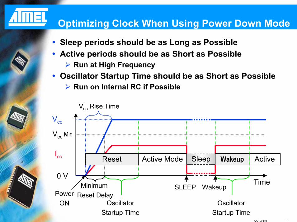
® Optimizing Clock When Using Power Down Mode
Sleep periods should be as Long as PossibleActive periods should be as Short as Possible
Run at High FrequencyOscillator Startup Time should be as Short as Possible
Run on Internal RC if Possible
Vcc Min
Vcc
Time0 V
PowerON
Minimum Reset Delay
Vcc Rise Time
OscillatorStartup Time
Active ModeReset
SLEEP Wakeup
Wakeup
OscillatorStartup Time
ActiveIcc Sleep
5/7/2003 7
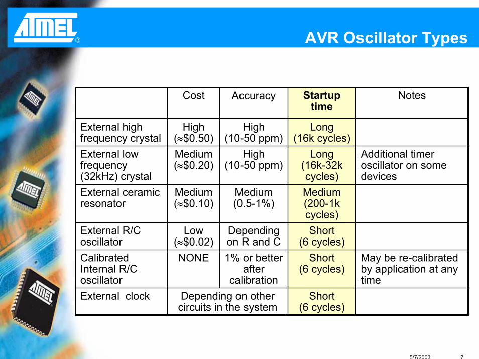
® AVR Oscillator Types
Additional timer oscillator on some devices
Long (16k-32k cycles)
High(10-50 ppm)
Medium (≈$0.20)
External low frequency (32kHz) crystal
Short(6 cycles)
Dependingon R and C
Low(≈$0.02)
External R/C oscillator
Short(6 cycles)
Depending on other circuits in the system
External clock
May be re-calibrated by application at any time
Short(6 cycles)
1% or better after
calibration
NONECalibrated Internal R/C oscillator
Medium (200-1k cycles)
Medium(0.5-1%)
Medium(≈$0.10)
External ceramic resonator
Long (16k cycles)
High(10-50 ppm)
High (≈$0.50)
External high frequency crystal
NotesStartuptime
AccuracyCost

5/7/2003 8
® Using Sleep Modes
Lower Average Power Consumption may be Acquired by Optimum Usage of Power Down Modes
Running a Device at High Speeds may Yield Lower Average Power Consumption due to Shorter ’On’ Time
Power
Time
Average Average

5/7/2003 9
® AVR Sleep ModesIdle Mode
CPU Stopped, Oscillators & Most I/O Modules ActiveAllows for Fast Wakeup from Sleep
ADC Noise Reduction ModeLike Idle Mode with Fewer I/O Modules Active
Power Down ModeCPU & Oscillator Stopped, Most Functions InactiveSlow Wakeup from Sleep – Oscillator must be Restarted
Power Save ModeLike Power Down Mode with 32 kHz Oscillator Running
Standby ModeLike Power Down Mode but Main Oscillator RunningAllows for Fast Wakeup from Sleep
Extended StandbyBoth Main Oscillator and 32 kHz Oscillator RunningAllows for Fast Wakeup from Sleep

5/7/2003 10
®
tiny2313V
mega162V
mega169V
mega88V
mega48V
mega168V
New 1.8 Volt AVR Devices
tiny11Ltiny12Ltiny13Ltiny15Ltiny2313Ltiny26Ltiny28L
mega48Lmega8Lmega8515Lmega8535Lmega88Lmega16Lmega162Lmega168Lmega169Lmega32Lmega64Lmega128L
tiny11tiny12tiny13tiny2313tiny26
mega48mega8mega8515mega8535mega88mega16mega162mega168mega169mega32mega64mega128
1.8 Volts
tiny12V
tiny13V
3.3 Volts 5 Volts1.8 - 5.5 V 2.7 - 5.5 V 4.0 - 5.5 V

®
~ HARDWARE DESIGN ~
Avoid the Most Common Design Flaws
5/7/2003 12
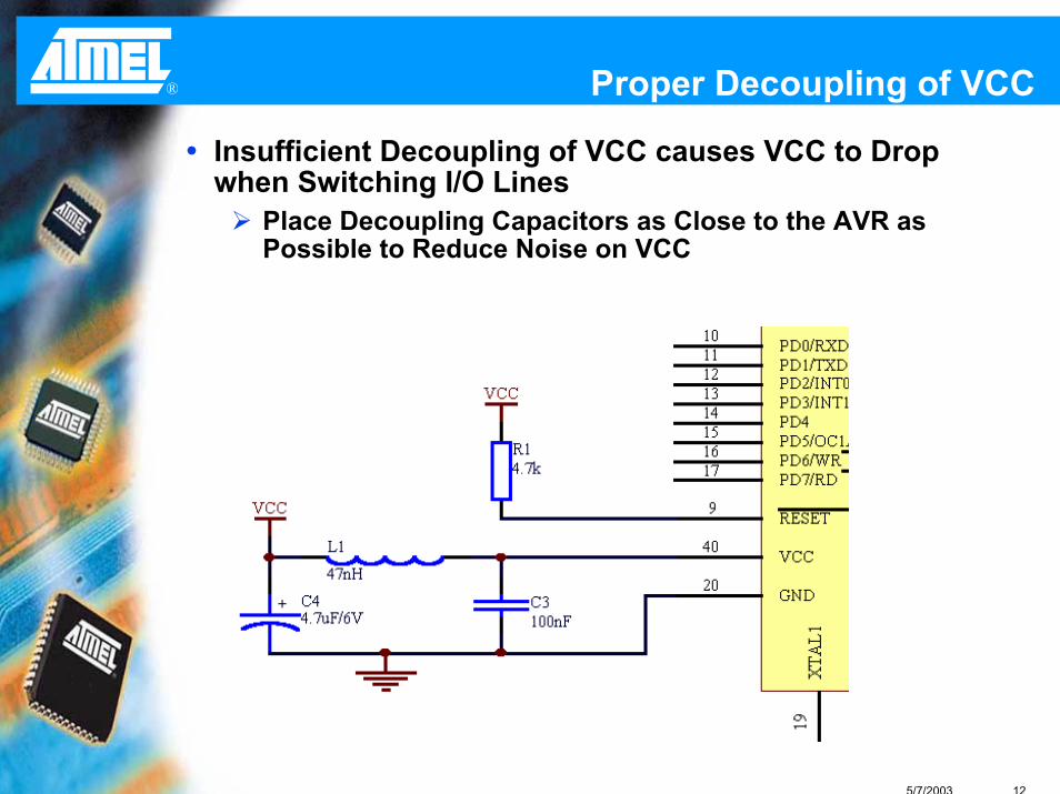
® Proper Decoupling of VCC
Insufficient Decoupling of VCC causes VCC to Drop when Switching I/O Lines
Place Decoupling Capacitors as Close to the AVR as Possible to Reduce Noise on VCC
5/7/2003 13
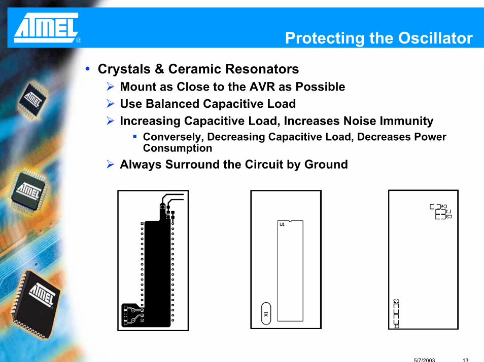
® Protecting the Oscillator
Crystals & Ceramic ResonatorsMount as Close to the AVR as PossibleUse Balanced Capacitive LoadIncreasing Capacitive Load, Increases Noise Immunity
Conversely, Decreasing Capacitive Load, Decreases Power Consumption
Always Surround the Circuit by Ground
5/7/2003 14
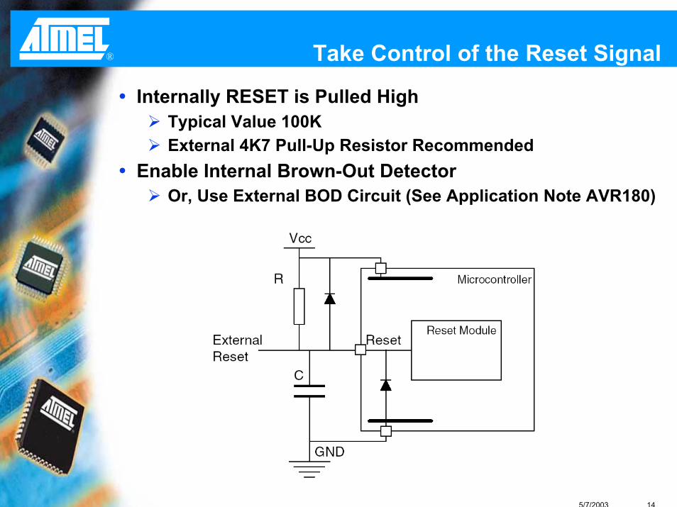
® Take Control of the Reset Signal
Internally RESET is Pulled HighTypical Value 100KExternal 4K7 Pull-Up Resistor Recommended
Enable Internal Brown-Out DetectorOr, Use External BOD Circuit (See Application Note AVR180)

5/7/2003 15
® AVR Hardware Design Hints
AVR040: EMC Design ConsiderationsVCC & GND ConnectionsReset Input
12 Volt Programming Voltage on RESET LineRESET is Asynchronous
AVR042: General Design ConsiderationsXTAL1 Capacitor Effects Higher Immunity Against BurstsXTAL2 Capacitor Effects Higher Current

5/7/2003 16
® Design Question
What is the minimum number of I/O pins required to control twelve LEDs, using no other components except current limiting resistors?
A) 3B) 4C) 6D) 12Using the Tri-State Capabilities of the I/O Pins, it is
possible to control up to Twelve LEDs with Four I/O Pins!

5/7/2003 17
® Design QuestionExample –
PB0 = ‘0’, PB1 = ‘1’, PB2/3 = HiZD10 = On, All Other LEDs Off
PB1
PB3
PB0
PB2
D10LED
D20LED
D01LED
D21LED
D31LED
D02LED
D12LED
D32LED
D03LED
D13LED
D23LED
R1270
R2270
R3270
R4270
D30LED

®
Efficient C-coding for AVR
Hints & Tricks to Reduce Code Size
5/7/2003 19
® Created for ‘C’
Instruction Set Designed for CExcellent 16 and 32-Bit SupportEfficient Bit Manipulation
Architecture Designed for CRegister File Reduces Data Handling OverheadLarge and Linear Memory MapMany Memory Pointers
The AVR Architecture and Instruction Set was Designed in Conjunction with IAR Systems:
Compiler Development Project Initiated before Architecture and Instruction Set FrozenCompiler Experts’ Advice Implemented in HardwarePotential HLL Bottlenecks Identified and Removed

5/7/2003 20
® AVR Benefits with ‘C’
Up to 50% Smaller Code Footprint Compared to Other Architectures
No Code Size Penalty Over Assembly, at a Fraction of the Development Time
Maintainable Code with Less Engineering Cost
Reusable Code for Upcoming Projects Saves Development Time

5/7/2003 21
® Assembly versus ‘C’
Full Control of Resource Usage
Compact and Fast Code in Small Applications
Inefficient Code in Larger Applications
Cryptic Code
Hard to Maintain
Not Portable
Limited Control of Resource Usage
Larger/Slower Code in Small Applications
Efficient Code in Larger Applications
Structured Code
Easy to Maintain
Easily Portable

5/7/2003 22
® 16-Bit Variables
Always use the Smallest Possible Data Types
16-Bit Counter:int count16 = 5; do{ }while(--count16);
LDI R24,LOW(5)LDI R25,0SBIW R24,LWRD(1)BRNE ?0004
Total 8 Bytes
8-Bit Counter:char count8 = 5; do{ }while(--count8);
LDI R16,5DEC R16BRNE ?0004
Total 6 Bytes
5/7/2003 23
® Global and Local Variables
Local VariablesInitialized at Function Start
Stored in a Register
Resides in the Register until the Function Exits
Global Variables Initialized at Startup
Stored in SRAM
Must be Loaded into Register File

5/7/2003 24
® Global versus Local Variables
Local Variable:
void main(void){char local;local = local-45;
}
SUBI R17,LOW(45)
Global Variable:char global;void main(void){global = global-45;
}
LDS R16,LWRD(global)SUBI R16,LOW(45)STS LWRD(global),R16
Total 2 Bytes Total 10 Bytes
Limit the use of Global Variables!

5/7/2003 25
® Direct Access of Global Variables
‘C’ Codeint t_count;char sec;char min;
void main(void){
sec++;min++;t_count++;
}
Assembly CodeLDS R16,LWRD(sec) ←SUBI R16,LOW(255)
STS LWRD(sec),R16 ←LDS R16,LWRD(min) ←SUBI R16,LOW(255)
STS LWRD(min),R16 ←LDS R16,LWRD(t_count) ←LDS R17,LWRD(t_count+1) ←SUBI R16,LOW(255)SBCI R17,LOW(0)
STS LWRD(t_count),R16 ←STS LWRD(t_count+1),R17 ←
← 4-byte instructions
Code Size: 40 Bytes
5/7/2003 26
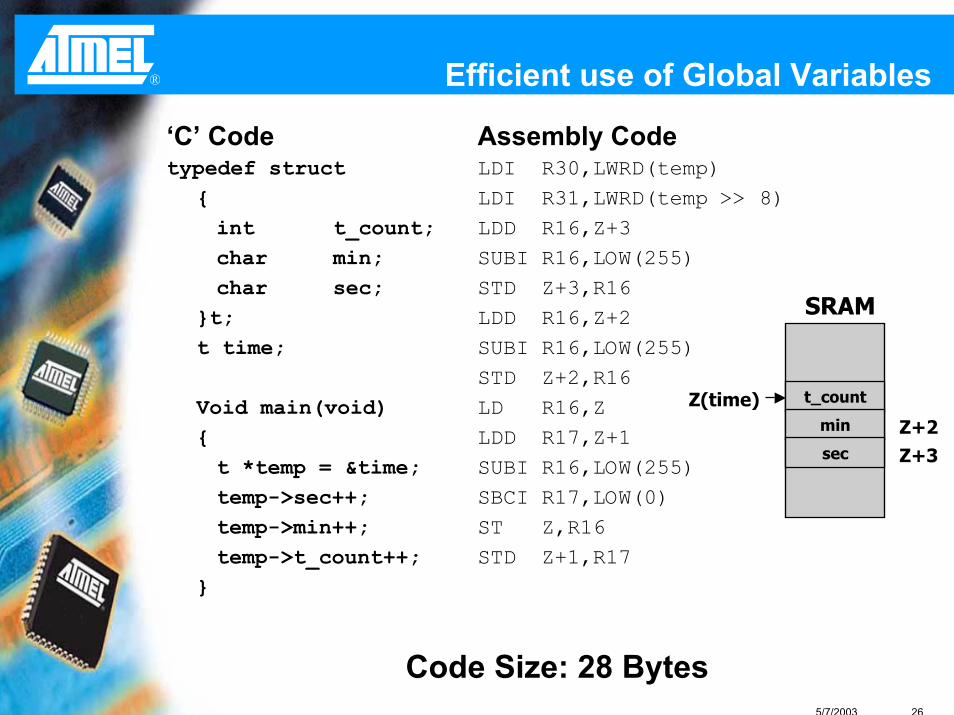
® Efficient use of Global Variables
Assembly CodeLDI R30,LWRD(temp)LDI R31,LWRD(temp >> 8)LDD R16,Z+3SUBI R16,LOW(255)STD Z+3,R16LDD R16,Z+2SUBI R16,LOW(255)STD Z+2,R16LD R16,ZLDD R17,Z+1SUBI R16,LOW(255)SBCI R17,LOW(0)ST Z,R16STD Z+1,R17
Code Size: 28 Bytes
t_count
min
sec
SRAM
Z(time)Z+2Z+3
‘C’ Codetypedef struct
{int t_count; char min; char sec;
}t;t time;
Void main(void){ t *temp = &time;temp->sec++;temp->min++;temp->t_count++;
}

5/7/2003 27
® Reuse Code
Compiler Recognizes Similar Code Pieces and Collects them in FunctionsCollect Similar Code in Modules
5/7/2003 28
® Checklist to Optimize Code
Compile with Full Size OptimizationUse Local Variables whenever PossibleUse Smallest Applicable Data TypeCollect Global Variables in Structures
READ THE GENERATED ASSEMBLY CODE !!

®
~ DEVELOPMENT TOOLS ~

5/7/2003 30
® AVR Tools Overview
STK500 STK501 STK502
Starter KitsCompilersIAR SystemsCodeVisionImageCraftGCC-AVR
AVR StudioNew AVR Device
AVRISP JTAGICE
In System Programmers
Emulator Platforms
ICE200JTAGICEICE40/50

5/7/2003 31
® AVR Studio
Integrated Development Environment for AVRInlcudes Atmel Macro Assembler
Front End for Atmel Starter Kits, Programmers, and EmulatorsC and Assembly Source Level DebuggingSupports Third Party CompilersMaintains Project Information Freely Available from http://www.atmel.com

5/7/2003 32
® AVR Studio
Macro AssemblerSupports All AVR Devices
SimulatorEarly Support for New AVR Devices
Emulator InterfaceasicICE (Studio 3 Only)ICE200ICE40/50JTAGICE
Programming InterfaceAVR ISPSTK500/501/502
Integrated Development EnvironmentSource File Editor
Assembly and ‘C’ Statement Highlighting
5/7/2003 33
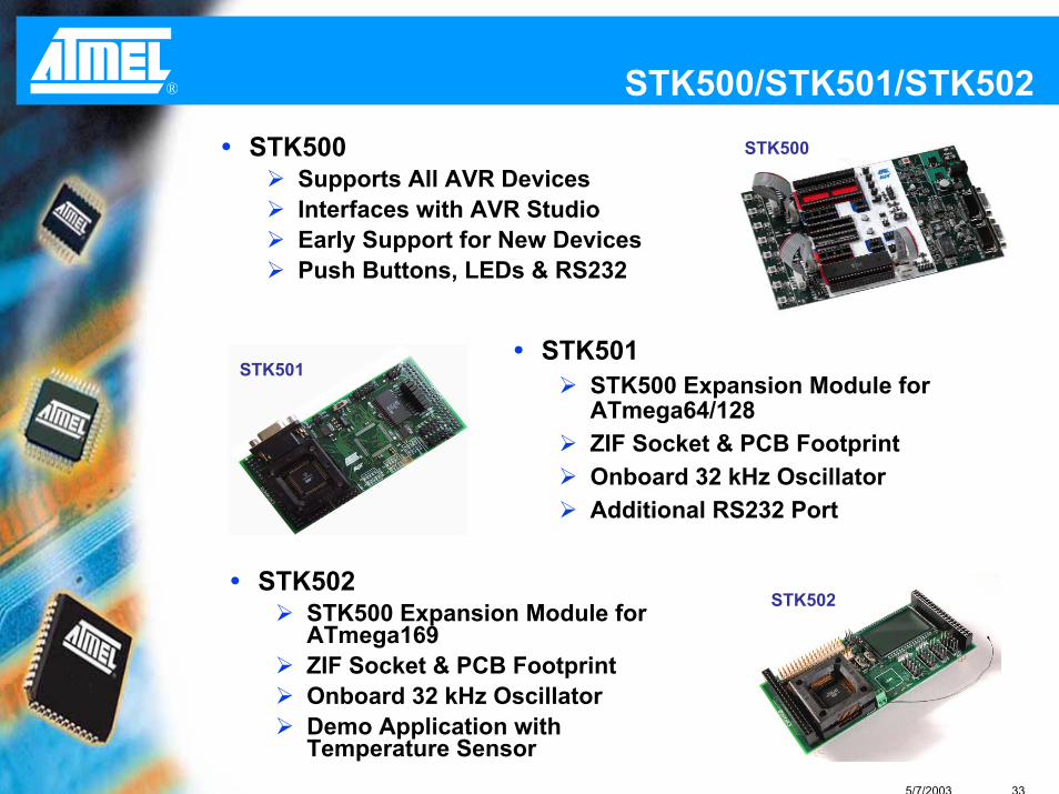
® STK500/STK501/STK502STK500STK500
Supports All AVR DevicesInterfaces with AVR StudioEarly Support for New DevicesPush Buttons, LEDs & RS232
STK501STK500 Expansion Module for ATmega64/128ZIF Socket & PCB FootprintOnboard 32 kHz OscillatorAdditional RS232 Port
STK501
STK502STK500 Expansion Module for ATmega169ZIF Socket & PCB FootprintOnboard 32 kHz OscillatorDemo Application with Temperature Sensor
STK502

5/7/2003 34
® FPSLIC Development KitsSTK94
AT94K40 FPSLIC & ConfiguratorTwo RS232 Serial PortsPush Buttons, LEDs, RS232 & Alpha-Numeric DisplaysSystem Designer Tool with Four Month License
STK594STK500 Expansion ModuleAT94K10 FPSLIC & ConfiguratorJTAG On-Chip Debug InterfaceOnboard 32 kHz OscillatorAdditional RS232 PortSystem Designer Tool with Four Month License

5/7/2003 35
® USB Development KitsAT43DK320A
Sample Application Code & Hardware Design DocumentationCan operate as Compound Device or Function Only
AT43DK355Sample Application Code & Hardware Design DocumentationUSB 2.0 Compliant Firmware LibraryUSB Application Wizard Compatible
AT43DK325/326Features Hot Keys, LEDs & Scan InputsUSB 2.0 Compliant Firmware LibraryCustomizable Keyboard MatrixHot Keys Software Available
5/7/2003 36
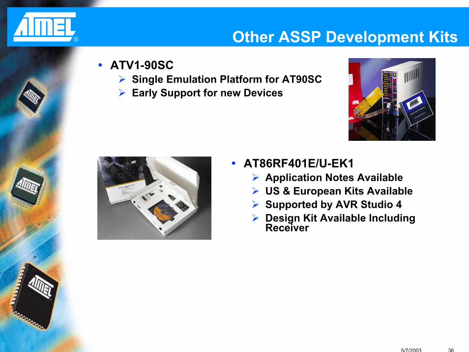
® Other ASSP Development KitsATV1-90SC
Single Emulation Platform for AT90SCEarly Support for new Devices
AT86RF401E/U-EK1Application Notes AvailableUS & European Kits AvailableSupported by AVR Studio 4Design Kit Available Including Receiver

5/7/2003 37
® AVRISP
Supports Serial In-System Programmable AVR Devices
Early Support for New AVR Devices via Firmware
Uses AVR Studio as Front End Programming Software
DOS Command Line Software Available
Supports Both 6- and 10-pin ISP ConfigurationsAdjustable Programming Speeds
Clock Adjustable from 15 Hz to 3.69 MHz
Operates on Target Voltage Supply from 2.7V to 5.5V

5/7/2003 38
® JTAG ICE Programming
In Circuit Programming using JTAGICEHigh Speed Comparable to Parallel Programming
Example:JTAG - ATmega16 Write & Verify Approximately 5 SecondsParallel - ATmega16 Write & Verify Approximately 3 Seconds
Full Support for Lock Bits and FusesOnly 4 Data Lines Required

5/7/2003 39
® ICE200
Real Emulator at Starter Kit CostControlled by AVR StudioSupports
Program BreakpointsFull Execution ControlFull I/O View & Watches
Real Time Emulation in AVR Silicon
Emulator Chip Made in the Same Process as the Real DevicePersonality Adapters Provide the Footprint for each Device
AVRSMDLow Cost Surface Mount Adapter Kit for the ICE200
ICE200
AVRSMD
5/7/2003 40
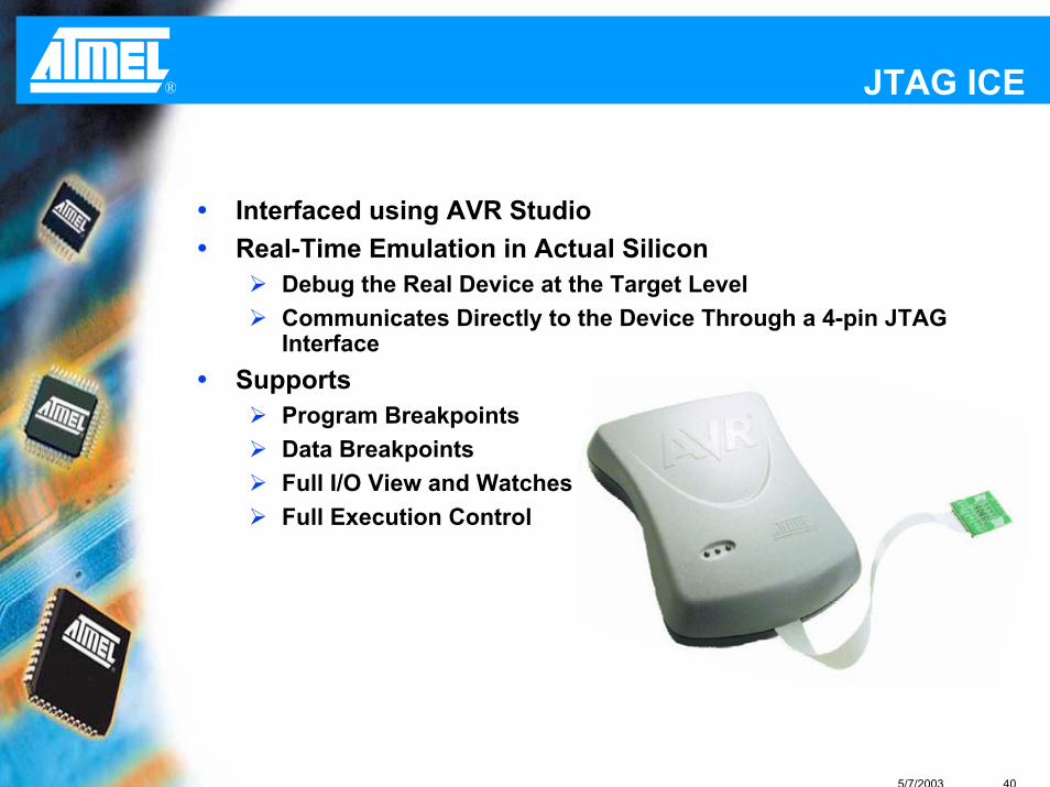
® JTAG ICE
Interfaced using AVR StudioReal-Time Emulation in Actual Silicon
Debug the Real Device at the Target LevelCommunicates Directly to the Device Through a 4-pin JTAG Interface
SupportsProgram BreakpointsData BreakpointsFull I/O View and WatchesFull Execution Control
5/7/2003 41
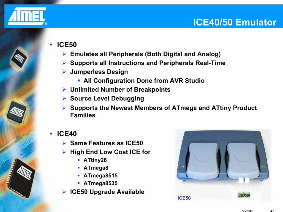
® ICE40/50 Emulator
ICE50Emulates all Peripherals (Both Digital and Analog)Supports all Instructions and Peripherals Real-TimeJumperless Design
All Configuration Done from AVR StudioUnlimited Number of BreakpointsSource Level DebuggingSupports the Newest Members of ATmega and ATtiny Product Families
ICE40Same Features as ICE50High End Low Cost ICE for
ATtiny26ATmega8ATmega8515ATmega8535
ICE50 Upgrade AvailableICE50

5/7/2003 42
® tinyAVR Starter Kits
AVRISP STK500
tiny11 Xtiny12 X Xtiny13 X Xtiny15 X X
tiny2313 X Xtiny26 X Xtiny28 X
5/7/2003 43
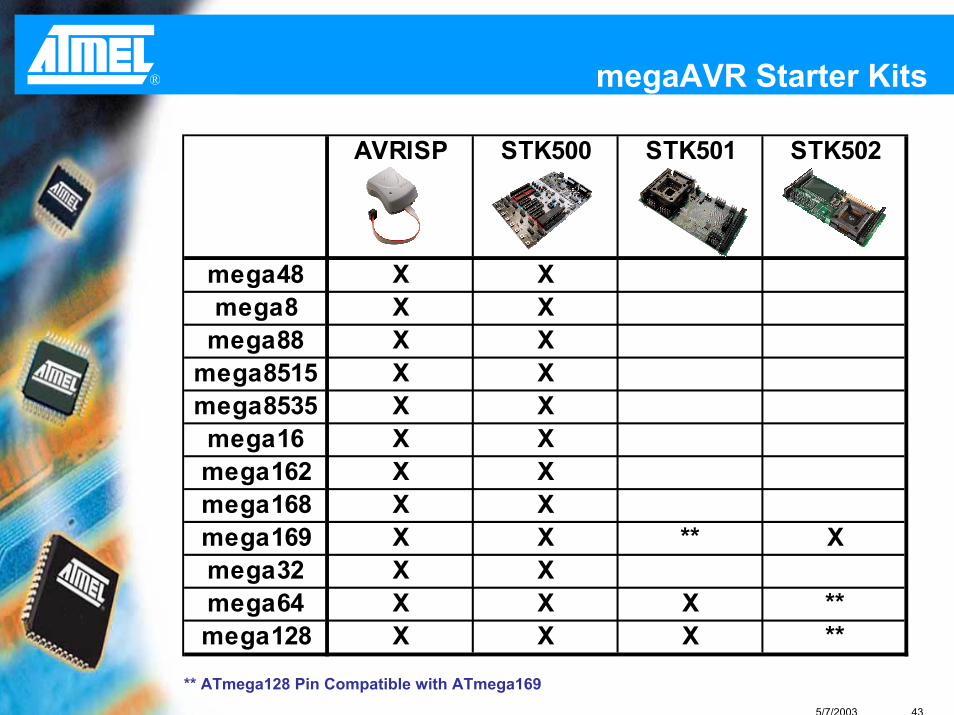
® megaAVR Starter Kits
** ATmega128 Pin Compatible with ATmega169
AVRISP STK500 STK501 STK502
mega48 X Xmega8 X X
mega88 X Xmega8515 X Xmega8535 X Xmega16 X Xmega162 X Xmega168 X Xmega169 X X ** Xmega32 X Xmega64 X X X **mega128 X X X **

5/7/2003 44
® tinyAVR Emulators
ICE200 ICE40 ICE50
tiny11 Xtiny12 Xtiny13 Xtiny15
tiny2313 Xtiny26 X Xtiny28

5/7/2003 45
® megaAVR Emulators
JTAGICE ICE40 ICE50
mega48 Xmega8 X X
mega88 Xmega8515 X Xmega8535 X Xmega16 X Xmega162 X Xmega168 Xmega169 X Xmega32 X Xmega64 X Xmega128 X X
5/7/2003 46
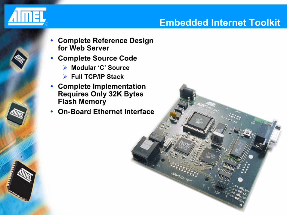
® Embedded Internet Toolkit
Complete Reference Design for Web ServerComplete Source Code
Modular ‘C’ SourceFull TCP/IP Stack
Complete Implementation Requires Only 32K Bytes Flash MemoryOn-Board Ethernet Interface

5/7/2003 47
® Battery Charger Kit
Reference Design based on Buck ConverterComplete Source Code Provided
Both Assembly and ‘C’tiny15 and mega8 as TargetSupports Multiple Battery Types
SLA, NiCd, NiMh, and Li-Ion Batteries
RS232 Port Available for General Use

5/7/2003 48
® AVR Butterfly
Complete Reference Design based on ATmega169
Low Power Design Methodologies
Features –SPI, USART, and USI CommunicationsProgramming Interfaces
Boot Sector, JTAG, ISP, and ParallelLight and Temperature SensorsPiezo Element for Sound GenerationJoystick Control Element
Collateral AvailableComplete Source Code and Users Guide Available from Atmel Website

5/7/2003 49
® Third Party Vendors
Compilers16+ Companies
Basic, C, C++, Forth, Pascal, etcProgrammers
35+ CompaniesField Service, ISP, JTAG, Parallel, and Production
Real Time Operating Systems8+ Companies
Adapters5+ Companies
Emulator, Programming, Prototype, and Logic Analyzer Adapters
>> See Third Party Vendors on ATMEL Website for Complete List <<

5/7/2003 50
® AVR Compilers
Third Parties Provide a Full-Scale of ‘C’ CompilersLow Cost to High End Compilers
High End CompilersIAR Embedded WorkBench AVR for AT90S and ATmega
Low Cost CompilersImageCraft ICCAVR for AT90S and Atmega (No 90S1200)ImageCraft ICCtiny for ATtiny and 90S1200CodeVisionAVR for AT90S and ATmega (No 90S1200)
FreewareGNU AVR-GCC for ATtiny, AT90S, and ATmega

5/7/2003 51
® Third Party C Compilers
++++++++++Integration with AVR
Studio
+++++++++Ease of Use
--
+++
$++
CodeVision
-√-Supports tinyAVR
√--Open Source
-++++Technical Support
Free$$$$Cost+++++++Code Size
GNU GCCImageCraftIAR

5/7/2003 52
® I Need Help!
www.atmel.comSelection Guides, Flyers, Datasheets, Application Notes, FAQ, and Errata Sheets
www.AVRfreaks.netAVR Experts Discussion ForumDesign Notes and Reference DesignsAtmel and Third Party ToolsSoftware, User Guides and LinksConsultants, Distributors and Atmel Representatives
[email protected] Support Hotline

®
~ APPLICATION EXAMPLE ~

5/7/2003 54
® Application Challenge
Design a Battery Powered Thermostat Serving Different Markets with Different Feature Sets
Commercial, Industrial, Residential, etc.
Thermostat Powered by Two AA Batteries10 Year Battery Life Requirement
Total System Cost Targeted at $5Batteries Not Included
5/7/2003 55
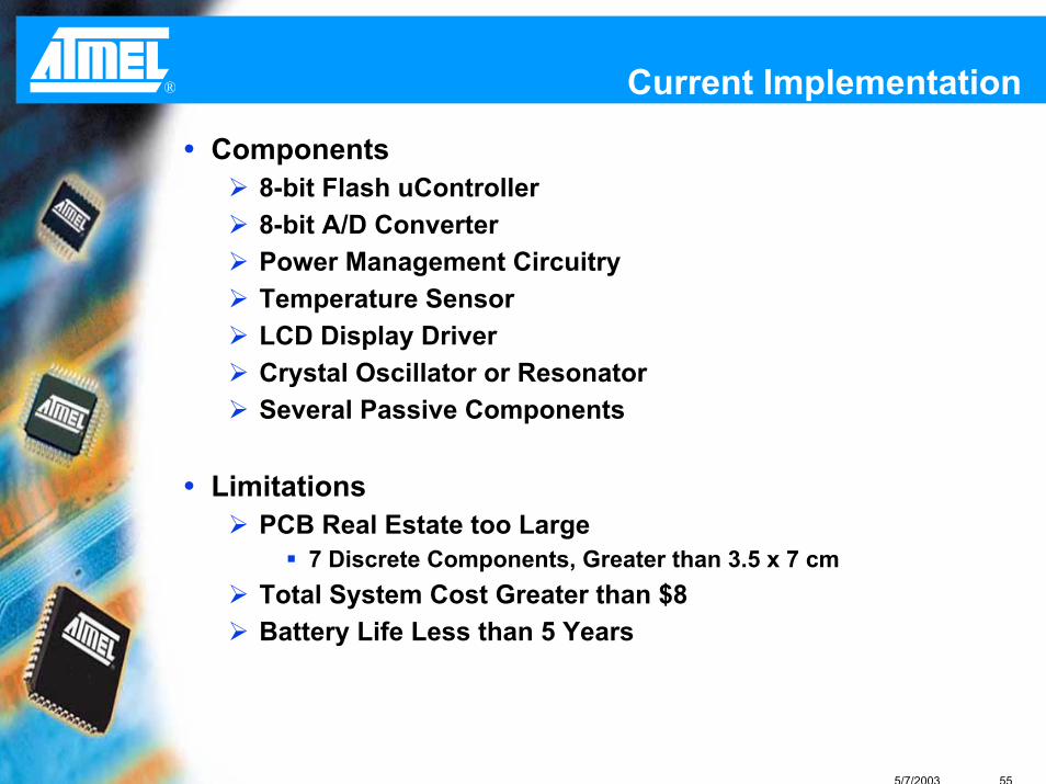
® Current Implementation
Components8-bit Flash uController8-bit A/D ConverterPower Management CircuitryTemperature SensorLCD Display DriverCrystal Oscillator or ResonatorSeveral Passive Components
LimitationsPCB Real Estate too Large
7 Discrete Components, Greater than 3.5 x 7 cmTotal System Cost Greater than $8Battery Life Less than 5 Years

5/7/2003 56
® Design Challenges
Design for Cost ObjectivesTarget Goal to Reduce System Cost by 35%
Alternative Component SolutionsReduce Component Count with Hardware IntegrationHigh Level of Hardware/Software IntegrationRequire Low Power uController and Discrete Components
Quick Time to MarketMajority of Time Spent on DesignEase of Manufacturing, No Wasted Time on Procurement

5/7/2003 57
® ATmega169
Key Features for Thermostat ApplicationsLCD Module
100 Segment Display – 25 Segment Lines & 4 Common LinesAutomatic Programmable Contrast ControlDuty Cycle – Static, 1/2, 1/3, and 1/4Bias Voltage – Static, 1/2, and 1/3
A/D Module10-bit A/D with Differential Channels – Increased AccuracyOn-Chip Analog Reference Eliminates External Reference
Power ConsumptionOperates Down to 1.8 Volts Current Consumption in Active Mode – 300 uA @ 1 MHzCurrent Consumption in Power Down Mode < 0.5 uA
Memories16K Bytes Self Programming Flash512 Bytes EEPROM and 1K Bytes SRAM
Packaging64-pin Micro Lead Frame Package, 9 x 9 mm2
Maximum Functionality at Minimum Pin Count

5/7/2003 58
® Automatic Contrast Control
Correct Setting of LCD Contrast Requires Matching of Different Voltage and Temperature Combinations
External Temperature Sensor Communicates withuController
Correct Voltage is Generated from On-Chip LCD Driver between 2.60 to 3.35 VoltsBias Voltage can be Greater than VCC
Lower Chip CountNo Need for External Circuit

5/7/2003 59
® Benefits of Integration
Power ConsumptionSingle Chip Solution Reduces Power Consumption by 50%
Using ATmega169 Allows for Discrete Components to become uController PeripheralsPrevious Implementation Consumed Majority of Power in I/O Modules when Interfacing Discrete DevicesI/O of Peripherals are now Nodes Inside AVR
Lower System CostFewer ComponentsReduced PCB “Real Estate”
Improved ReliabilityFewer Components to Test

5/7/2003 60
® Cost ComparisonProposed Solution Existing Solution
ATmega169 $3.00 8-bit uC $2.50 LCD Panel $1.00 LCD Panel $1.00 Temp Sensor $0.40 Temp Sensor $0.40 Passives $0.20 Passives $0.50 Plastic Case $0.30 Plastic Case $0.30 PCB Board $0.10 PCB Board $0.10 A/D $1.50 LCD Interface $0.90 Brown Out $0.50 Crystal $0.30
Total Cost $5.00 Total Cost $8.00

5/7/2003 61
® ManufacturingOne Thermostat to Serve Multiple Markets
Marketing Forecasts Change
In-System Flash Program MemorySimplifies Inventory ManagementJust-In-Time DeliveryNo Scrap due to Code PatchesProgram Different Codes at End of Line
JTAG InterfaceBoundary ScanProgramming


![AVR - dl.melec.irdl.melec.ir/download/pdf/AVR/CodeVision-Fusebit[Melec.ir].pdf · AVR AVR AVR AVR 01 CodeVision CKSEL3..0 Device Clocking Option CKSEL3..0 External Crystal/Ceramic](https://img.dokumen.tips/doc/110x75/5cf6e10d88c99387248bfc0e/avr-dlmelecirdlmelecirdownloadpdfavrcodevision-fusebitmelecirpdf.jpg)