Embed Size (px)
Citation preview
Designing Trail Termini
Introduction
1
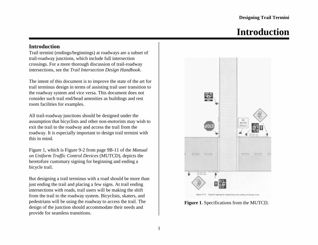
Figure 1. Specifications from the MUTCD.
IntroductionTrail termini (endings/beginnings) at roadways are a subset oftrail-roadway junctions, which include full intersectioncrossings. For a more thorough discussion of trail-roadwayintersections, see the Trail Intersection Design Handbook.
The intent of this document is to improve the state of the art fortrail terminus design in terms of assisting trail user transition tothe roadway system and vice versa. This document does notconsider such trail end/head amenities as buildings and restroom facilities for examples.
All trail-roadway junctions should be designed under theassumption that bicyclists and other non-motorists may wish toexit the trail to the roadway and access the trail from theroadway. It is especially important to design trail termini withthis in mind.
Figure 1, which is Figure 9-2 from page 9B-11 of the Manualon Uniform Traffic Control Devices (MUTCD), depicts theheretofore customary signing for beginning and ending abicycle trail. But designing a trail terminus with a road should be more thanjust ending the trail and placing a few signs. At trail endingintersections with roads, trail users will be making the shiftfrom the trail to the roadway system. Bicyclists, skaters, andpedestrians will be using the roadway to access the trail. Thedesign of the junction should accommodate their needs andprovide for seamless transitions.

Designing Trail Termini
General Guidelines
2
Not all trails end at right angles with two-lane roads as depictedin the MUTCD figure, although this is generally a moredesirable goal when compared to endings at roads of four ormore lanes. Like roadway-roadway intersections, trail-roadwayjunctions can be of a variety of configurations and range fromsimple to complex. The goal should be to design so thatpotentially complex situations are simplified.
The following guidelines are suggested when designing trailtermini. See also the Trail Intersection Design Handbook foradditional guidelines when constructing trail intersections.
General Guidelines for Designing Trail Termini 1. Analyze the tasks of both trail users (bicyclists, skaters, and
pedestrians) and motorists, and study the discrepancies betweenplanned for and actual behavior. The design should take intoaccount trail user desire lines.
2. Terminate the trail at the lowest point of the street hierarchypossible. It is generally better to end on a minor residential streetthan on a principle arterial if the choice exists. Trail users canthen work their way up the street hierarchy to their destinationor their highest point of comfort.
3. Provide sidewalks along the intersecting road for pedestrians,and recognize that some bicyclists may also use these whetherspecifically intended for bicyclists or not. Sidewalks may becarefully designed to accommodate bicyclists in limited andspecial circumstances.
4. Include positive guidance such as signs, pavement markings,and channelization to induce bicyclists to ride on the proper sideof the road, with traffic.
5. Provide educational materials for bicyclists, skaters, andpedestrians.
6. If the trail is terminated on a one-way street, consider a contra-flow bicycle lane to enhance bicycle transportationopportunities, and to accommodate inevitable would-be wrongway riders.
7. Restrict parking near the trail terminus, as would be done for astreet or driveway junction.
8. A trail-roadway terminus can be an excellent location toimplement motor vehicle traffic calming measures.
9. Where the trail ends at a busy midblock location, consider a jughandle design to assist left turning road bicyclists in making aright angle crossing to access the trail.
Designing Trail Termini
Education
3
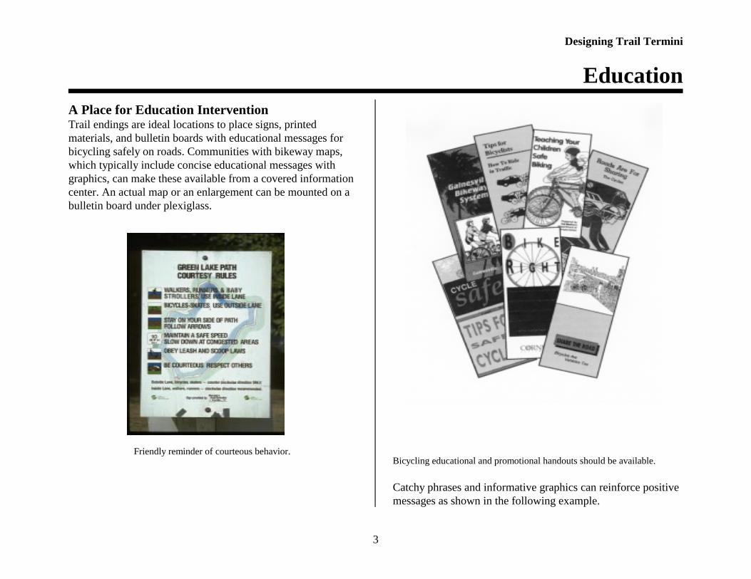
A Place for Education InterventionTrail endings are ideal locations to place signs, printedmaterials, and bulletin boards with educational messages forbicycling safely on roads. Communities with bikeway maps,which typically include concise educational messages withgraphics, can make these available from a covered informationcenter. An actual map or an enlargement can be mounted on abulletin board under plexiglass.
Friendly reminder of courteous behavior. Bicycling educational and promotional handouts should be available.
Catchy phrases and informative graphics can reinforce positivemessages as shown in the following example.

Designing Trail Termini
Using Sidewalks
4
Spoke ‘n’ Words for Bicyclists
< Ride a Safe Bicycle. Make sure the bicycle is the correctsize for you, is in proper working order, and that you arecompetent with all operating controls.
< Be Well Outfitted. Use bright clothing during the day,front and rear lights and reflectors at night, a helmet, andstiff soled footwear.
< Go With the Flow. Behave as though you are operating avehicle—because you are! Ride Right with traffic, notfacing traffic, and obey all laws, signs, and signals. Twowheels or four, the law is the law.
< Know these Skills. Be able to ride a straight line,including while starting and stopping, riding very slowly,“shoulder checking,” and hand signaling. Learn how to“quick turn,” “quick dodge,” and “panic stop.”
< Use Street Smarts. Watch out for road hazards likepotholes and gravel, and motor vehicles turning left infront of you and coming out of driveways or side streets.Ride at least a door’s width from parked cars. Use properdestination positioning—don’t go straight in a right turnlane for example.
< Be cautious not timid; assertive not aggressive. Don’tride in the gutter pan, near the extreme edge of the road,or on the sidewalk. Ride confidently and in control, likeyou’ve been there, done that.
Source: Wayne Pein, University of North Carolina Highway Safety Research
Center.
Using a Sidewalk as a Transition to the RoadIt is widely recognized that sidewalk bicycle riding should bediscouraged. Still, there may be certain situations when ridingon a sidewalk provides a reasonable alternative to road riding,assists with the transition to the roadway or trail, or is the bestcompromise of an otherwise bad situation. A sidewalkdesigned to accommodate bicyclists along with pedestrians ismore appropriately called a sidepath.
The city of Madison, WI recognizes there are situations where,because of infrastructural restrictions or bicyclist desire lines,sidewalk riding is likely. In those cases, efforts are made tominimize the negative consequences of sidewalk riding bydesigning the sidepath to better accommodate bicyclists.
Widened sidewalk.

Designing Trail Termini
Contra-flow Bicycle Lanes
5
If sidewalks are to be used for bicycling, the followingguidelines are recommended. The sidepath should be:< an option to using the roadway, and not the sole design
facility. The roadway should be easily accessible from thetrail and vice versa;
< used for a short distance only, cross few driveways, andhave sight lines as clear as practicable at driveways;
< continuous over driveways, rather than interrupted by thedriveway cut. Stop bars and/or stop signs and WATCHFOR BICYCLES signs should be considered to control andalert crossing motorists;
< wider than standard, signed for the presence of bicycletraffic (BICYCLES USING SIDEWALK; LOOK RIGHTFOR BICYCLISTS), and ideally be of a contrasting colorto the “normal” sidewalk.
Don’t do this. Provide a full width curb cut.
Contra-flow Bicycle LanesIf the trail terminates on a one-way street, it may be desirableto provide a contra-flow bicycle lane. According to the 1995Oregon State Bicycle and Pedestrian Plan, a contra-flowbicycle lane may be considered if: < it provides substantial time savings; < it affords direct access to high-use destinations; < it improves safety because of reduced conflicts as compared
to the longer route; < there are few intersecting driveways, alleys or streets on the
side of the contra-flow lane; < bicyclists can safely and conveniently re-enter the traffic
stream at either end of the section; < a substantial number of bicyclists are already using the
street facing traffic; < there is sufficient street width to also accommodate a
normal with-flow bicycle lane. In special circumstances, a contra-flow bicycle lane may beused on a very low volume one-way street without the use of awith-flow bicycle lane. Three such examples exist on theOregon State University campus where there is low motorvehicle volume and high bicycle volume.
The Oregon plan specifies the following design features forcontra-flow bicycle lanes:< place the contra-flow lane on the right side of the street (to
the motorists’ left);< separate the contra-flow lane from on-coming motor
vehicle traffic with a double yellow line to indicate that the

Designing Trail Termini
Case Studies
6
bicyclists are riding on the street legally, in adedicated travel lane;
< install ONE WAY Except For Bicycles, DO NOT ENTERExcept For Bicycles, WATCH FOR BICYCLES ON LEFTsigns on cross streets and driveways;
< existing traffic signals should be fitted with special signalsfor bicyclists with either loop detectors or easily reachedpush-buttons.
The contra-flow bicycle lane should also be evaluated for theinstallation of bicycle stop sign R1-1 or yield sign R1-2 at anyintersections, as well as for any other applicable signs asdescribed in the MUTCD.
A contra-flow bicycle lane.Source: Oregon State Bicycle and Pedestrian Plan.
Introduction to Case StudiesFive diverse trail termini intersections were examined atlocations across the country. These were the:< Hagar Drive Bicycle Path on the University of California at
Santa Cruz;< Libba Cotton Trail in Carrboro, North Carolina;< Pinellas Trail in Tarpon Springs, Florida;< Starkweather Creek Bicycle Path in Madison, Wisconsin;< Lake Hollingsworth Path in Lakeland, Florida.
Each situation is physically described, and observations andanalysis of bicyclist movements are discussed. A drawingdepicting the intersection and bicyclist design movements(those intended by the designer via the configuration of theintersection) and desire line movements (those that thebicyclists actually perform or would like to perform) isprovided. Lastly, recommendations for improving theintersection are offered. For all case studies except the PinellasTrail, a second drawing shows the intersection with thesuggested changes.
It is important to emphasize that the drawings arerepresentations only and are not to precise scale. Furthermore,recommendations are based on sound principles oftransportation engineering, but no engineering studies wereperformed, as this was beyond the scope of the examinations.Detailed engineering analysis is necessary to ensure thefeasibility of any intersection reconstruction.
Designing Trail Termini
Case Study I- Hagar Drive Bicycle Path
7
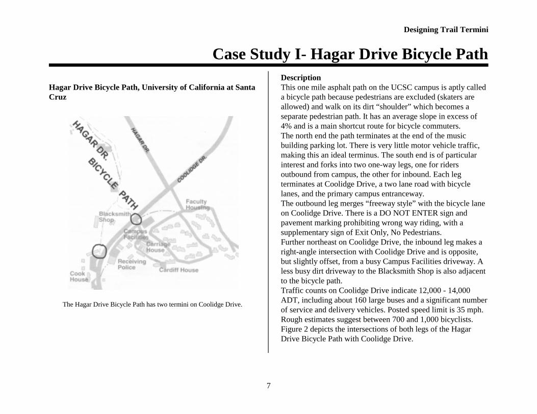
Hagar Drive Bicycle Path, University of California at SantaCruz
The Hagar Drive Bicycle Path has two termini on Coolidge Drive.
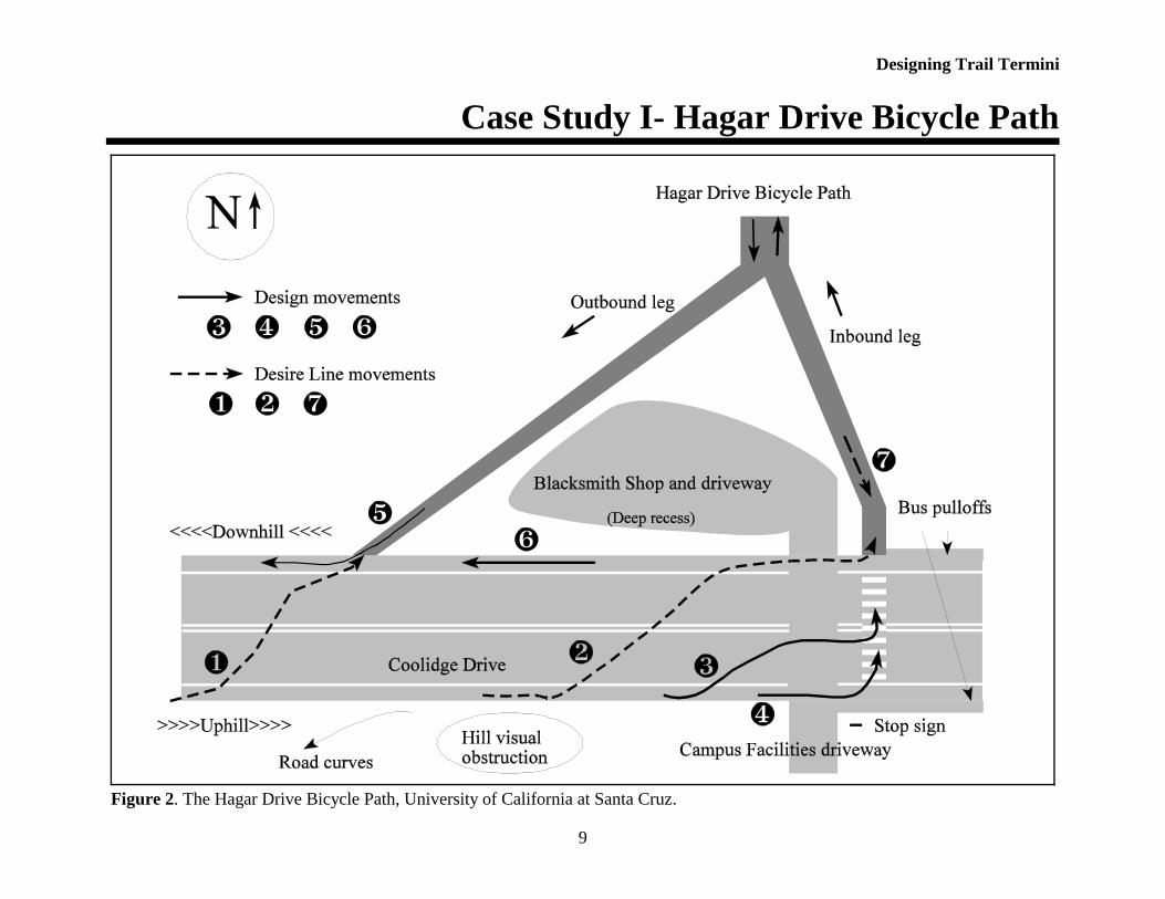
DescriptionThis one mile asphalt path on the UCSC campus is aptly calleda bicycle path because pedestrians are excluded (skaters areallowed) and walk on its dirt “shoulder” which becomes aseparate pedestrian path. It has an average slope in excess of4% and is a main shortcut route for bicycle commuters. The north end the path terminates at the end of the musicbuilding parking lot. There is very little motor vehicle traffic,making this an ideal terminus. The south end is of particularinterest and forks into two one-way legs, one for ridersoutbound from campus, the other for inbound. Each legterminates at Coolidge Drive, a two lane road with bicyclelanes, and the primary campus entranceway. The outbound leg merges “freeway style” with the bicycle laneon Coolidge Drive. There is a DO NOT ENTER sign andpavement marking prohibiting wrong way riding, with asupplementary sign of Exit Only, No Pedestrians.Further northeast on Coolidge Drive, the inbound leg makes aright-angle intersection with Coolidge Drive and is opposite,but slightly offset, from a busy Campus Facilities driveway. Aless busy dirt driveway to the Blacksmith Shop is also adjacentto the bicycle path.Traffic counts on Coolidge Drive indicate 12,000 - 14,000ADT, including about 160 large buses and a significant numberof service and delivery vehicles. Posted speed limit is 35 mph.Rough estimates suggest between 700 and 1,000 bicyclists.Figure 2 depicts the intersections of both legs of the HagarDrive Bicycle Path with Coolidge Drive.
Designing Trail Termini
Case Study I- Hagar Drive Bicycle Path
8
Designing Trail Termini
Case Study I- Hagar Drive Bicycle Path
9
Figure 2. The Hagar Drive Bicycle Path, University of California at Santa Cruz.

Designing Trail Termini
Case Study I- Hagar Drive Bicycle Path
10
Observations and Analysis Exiting the path.The merge design seems to work well. This is because of clearsight lines and the similar speeds of bicyclists both on the path(movement Ä) and on the bicycle lane (movement Å). A smallnumber of bicyclists go the wrong way on the inbound leg(movement Æ) and do so to access the Campus Facilitiesdriveway. Hagar Drive, which has bicycle lanes, parallels thepath a short distance to the east, and there are no destinationsbetween these facilities. Thus, there is no real need forbicyclists to make a left turn onto Coolidge Drive when exitingthe path—most would have used Hagar Drive.
Merging from the path to the bicycle lane (movement Ä).
Accessing the path.As designed, the bicyclist is required to proceed further uphill(than where the outbound leg of the bike path merges) on theCoolidge Drive bicycle lane and make a left turn at the laddercrosswalk to access the inbound leg, “design” movement  orÃ. It is a bit of a stretch to call these design movements, asnothing, such as a left turn bay, jug handle, or pavementmarking, is provided to facilitate their execution.
A substantial percentage of bicyclists cross over CoolidgeDrive prematurely and either go up the outbound leg(movement À) ignoring the DO NOT ENTER warnings, orride the wrong way in the westbound Coolidge Drive bicyclelane before turning left onto the inbound leg of the path (movement Á).
There are related reasons for this behavior. First, left turns canbe difficult at this location due to: (a) heavy and high speeddifferential motor vehicle traffic (bicyclists are moving veryslowly due to ascending); (b) conflicts at the crosswalk fromturning motor vehicles at the Campus Facilities and BlacksmithShop driveways, and the nearby bus pullouts; and (c) lack ofleft turn pockets. Second, riding the wrong way up theoutbound leg of the path (movement À) requires less climbingand time than proceeding further up Coolidge Drive to accessthe inbound leg, movements  and Ã.

Designing Trail Termini
Case Study I- Hagar Drive Bicycle Path
11

Designing Trail Termini
Case Study I- Hagar Drive Bicycle Path
12
Wrong way on the outbound leg of the path (movement À).
For these reasons, many bicyclists choose to cross overCoolidge Drive whenever the opportunity arises. It is simplymore convenient for bicyclists to do so rather than adhere to theprescribed “design” methods.
Recommendations Transportation officials are currently working to redesign andreconstruct the intersection. Signalization has been consideredbut is not warranted at this time. The project, which is intendedto also improve motor vehicle operations, proposes to:
< widen Coolidge Drive to provide left turn pockets in bothdirections;
< relocate the two bus stops to a new location;< widen and reconfigure the existing inbound leg to
accommodate two-way traffic;< shave the hillside on the southeast side of Coolidge Drive
to improve sight lines;< prepare the pavement with an eye to future signalization of
the intersection.
Initially, there was some interest in closing the outbound mergeleg and rerouting all bicycle traffic through the inbound leg.Bicyclists were critical of this, and that idea has been dropped.
These proposed changes are necessary and adequately addresssome of the difficulties that bicyclists face when attempting tomake a left turn and access the path. They do not addressbicyclists’ desire to minimize physical effort and timeexpended, however. This could be accomplished byreconfiguring the outbound merge leg for two-way bicycletraffic and enabling inbound bicyclists to access this part of thepath which is lower on the hill. Without an engineering study,it is unclear whether this is a viable option because the curve inCoolidge Drive restricts sight lines of high speed, downhill,westbound motor vehicle traffic, making a left turn bybicyclists at this location a potentially risky maneuver.
Figure 3 reflects the reconfiguration of the inbound leg for two-way bicycle traffic and aligning it with the Blacksmith Shopdriveway. Left turn bays have also been added which wouldlikely reduce or eliminate movements Á and Ã.

Designing Trail Termini
Case Study I- Hagar Drive Bicycle Path
13
Figure 3. The Hagar Drive Bicycle Path, Santa Cruz, California. Depicted with recommended changes.

14
This page left blank.

Designing Trail Termini
Case Study II- Libba Cotton Trail
15
Libba Cotton Trail, Carrboro, North Carolina
The Libba Cotton Trail bypasses a busy commercial area.
DescriptionThis multi-use trail is flat, 0.4 mile long, and is in an active butlightly used, slow speed railroad corridor. Approximately 700-1000 bicyclists and a much smaller number of pedestrians perday use this shortcut between Carrboro and Chapel Hill, NC,primarily for going to and from the University of NorthCarolina at Chapel Hill.
The west end terminates at the right angle bend of RobersonStreet, a short, low volume, and low speed commercial 2-lanestreet. There is nothing remarkable about this terminus, thoughthe curb cut apron is too steep, making an abrupt transition tothe roadway surface. It functions adequately due to theinfrequent and very slow motor vehicle traffic.
The east end terminates offset at a skew to the T-intersection ofMerrit Mill Road and Cameron Avenue. This intersection issignalized with a short cycle to reduce delay, and an exclusivepedestrian phase on immediate call stops all motorized traffic.
Merrit Mill is 2 lanes with a left turn lane, 20 mph north of thetrail and 35 mph to the south. Cameron Avenue is 3 lanes(center two-way turn lane), has part time bicycle/parking lanes,and is a primary access road to the university. Worn dirt pathsserve as “sidewalks” near the intersection (on the south side thedirt path becomes a legitimate bricked sidewalk approximately150 ft east of the intersection).
Figure 4 depicts the Libba Cotton Trail terminus at Merrit MillRoad and Cameron Avenue.

Designing Trail Termini
Case Study II- Libba Cotton Trail
16
Figure 4. The Libba Cotton Trail, Carrboro, North Carolina.

Designing Trail Termini
Case Study II- Libba Cotton Trail
17
Observations and AnalysisExiting the trailIn a ½ hour mid-morning period, 36 bicyclists exited the trail.Most bicyclists, 27 (75%), performed “design” movement À, avehicular style on-road left turn. Though referred to here as adesign movement, nothing in particular has been done tofacilitate this movement.
For movement Á, the bicyclist is directed, still off-road, to thepole-mounted pedestrian push button and walk/don’t walkindicator. Two bicyclists performed this maneuver, thoughneither used the pushbutton. Pedestrians exiting the trail alsoperform this movement.
Four bicyclists executed desire line movement Â, a left turnfrom the through lane. No motor vehicles were present to causea conflict resulting from this improper turn method. Desire linemovement à is characterized by wrong way riding followed bya midblock crossover to the correct side of the road. Three usedthis technique.
Accessing the trailNo effort in the design has been made to assist bicyclists to thetrail. All bicyclists accessing the trail from Cameron Avenuefollow desire line movement Ä which is the natural line. Theprecise lines bicyclists follow vary somewhat depending uponthe cross motor vehicle traffic situation on Merrit Mill Road,and whether motor vehicles are stacked, obstructing the trailentranceway.
Pedestrians are accommodated with a pushbutton and standarddesign crosswalk. The crosswalk is angled slightly away fromthe desired alignment to the trail, somewhat increasing walkingdistance
.
Natural line movement Ä to access the trail.

Designing Trail Termini
Case Study II- Libba Cotton Trail
18
Figure 6. The Libba Cotton Trail, Carrboro, North Carolina. Depicted with recommended changes.

Designing Trail Termini
Case Study II- Libba Cotton Trail
19
RecommendationsThis intersection performs adequately because of low motorvehicle speeds, clear sight lines, and a short traffic signal cyclewhich reduces bicyclist frustration and potential for infractions.Bicyclists can choose their level of comfort and conveniencewhen exiting the trail by making vehicular style movement À,or pedestrian style movement Á.
It may be beneficial to erect a “DO NOT BLOCK TRAIL” signfor southbound motor vehicles on Merrit Mill Road to helpensure bicyclist movement Ä access to the trail.
Another potential design solution for accessing the trail wouldbe to provide a straight through bicycle pocket with dashedbicycle lane channelization to enable bicyclists to cross theroad at a 90 degree angle (design movement Å on Figure 5).Still, in spite of this option it is likely bicyclists would continueto prefer the more direct movement Ä.

20
This page left blank.

Designing Trail Termini
Case Study III- Pinellas Trail
21
Pinellas Trail, Tarpon Springs, Florida.
The Pinellas Trail traverses many roads.
DescriptionNearly 30 miles long, the multi-use Pinellas Trail crosses morethan 80 roadways through several jurisdictions in PinellasCounty, Florida.
In Tarpon Springs, the trail is in a raised abandoned railroadbed in the center of Safford Avenue. Traveling north, at PineStreet the raised bed ends and trail users are directed to crossthe northbound lane of Safford Avenue to a refuge area, thencross Pine Street at a crosswalk. Trail users have the right-of-way, as the Pine Street/Safford Avenue intersection is a 4-waystop for motor vehicles and the stop signs are in advance of thetrail crosswalks.
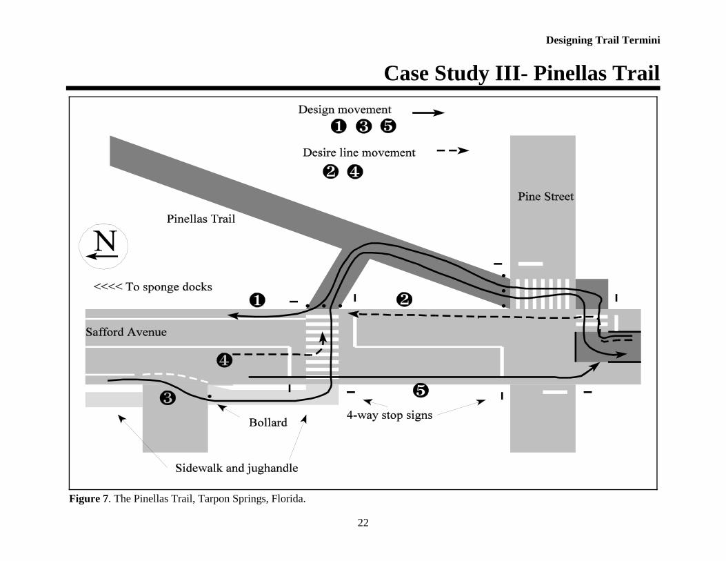
North of Pine Street, the trail occupies it’s own alignmentseparate from Safford Avenue. One block further north of PineStreet, a short spur trail reconnects with Safford Avenue, whichat this point has bicycle lanes and a sidewalk on the west side,giving trail users dedicated facilities for access to the popularsponge docks tourist area. A short stretch of sidewalk serves asa jug handle sidepath for southbound bicyclists on SaffordAvenue, enabling a right angle crossing of the roadway. Four-way stop signs control this trail terminus.
Safford Avenue is 25 mph and very low volume with aresidential character in this section of the trail.
Figure 6 shows this unique area of the Pinellas Trail.
Designing Trail Termini
Case Study III- Pinellas Trail
22
Figure 7. The Pinellas Trail, Tarpon Springs, Florida.

Designing Trail Termini
Case Study III- Pinellas Trail
23
Observations and AnalysisThis section has been designed with the philosophy of givingtrail users the opportunity to choose their level of comfort inmaking the transition from trail to roadway and vice versa.
Northbound bicyclistsDesign movement À provides novice bicyclists and pedestrianswith a conservative transition to the bicycle lanes and sidewalkon Safford Avenue. In practice, most bicyclists, especiallythose who are repeat users, follow the more direct desire linemovement Á, even though no special bicycle facilities areprovided for a short stretch of Safford Avenue.
Southbound bicyclistsDesign movement  provides bicyclists with a right anglecrossing of Safford Avenue for accessing the trail. Desire linemovement à is likely used by bicyclists wanting a more directreturn to the trail, and movement Ä by those desiring an evenmore direct route to the trial southbound.
RecommendationsThe overall design of this section of the trail seems to workwell. Bicyclists negotiating the Safford Avenue/Pine Streetintersection are not required to stop as are motorists. Thisperforms adequately due to thoughtful design forcing turns andslow speed by bicyclists, and the low speed and volume ofmotor vehicles.
Bicycle lanes could be striped just north of Pine Street onSafford Avenue, though motorized traffic is quite benign here.The bicycle lanes would simply serve a continuous bicyclefacilities function.
The sidepath jug handle enabling movement  is a design mostappropriate where the roadway carries significant traffic. Thisis not the case in this situation, so the design can be considered very conservative. The stop sign on Safford Avenue also makesa bicycling jug handle unnecessary. The bollard on the sidepathjug handle is an unnecessary motor vehicle deterrent andhazard to bicyclists.
The jug handle design is appropriate for pedestrians, however.Pedestrians are adequately accounted for with the use of thesidewalk, though future development in this area maynecessitate the addition of a sidewalk on the east side ofSafford Avenue.
The four-way stop at the trail jug handle crosswalk is overlyrestrictive. Either the trail or the roadway should be stopped,but not both.

24
This page left blank.
Designing Trail Termini
Case Study IV- Starkweather Creek Bicycle Path
25
Starkweather Creek Bicycle Path, Madison,Wisconsin
DescriptionThis one mile long asphalt path provides an importantcommuter link to bicyclists in the northeast area of Madisonwith the downtown and University of Wisconsin areas. It alsoprovides off-road access to the Madison Area TechnicalCollege.
The path terminus is on Anderson Street approximately 200feet from the intersection with Wright Street. Both streets arefour lanes, and no turning lanes are present. Anderson Streethas wide outside lanes and Wright Street bicycle lanes. Thisintersection is signalized with pedestrian pushbuttons at all fourcorners.
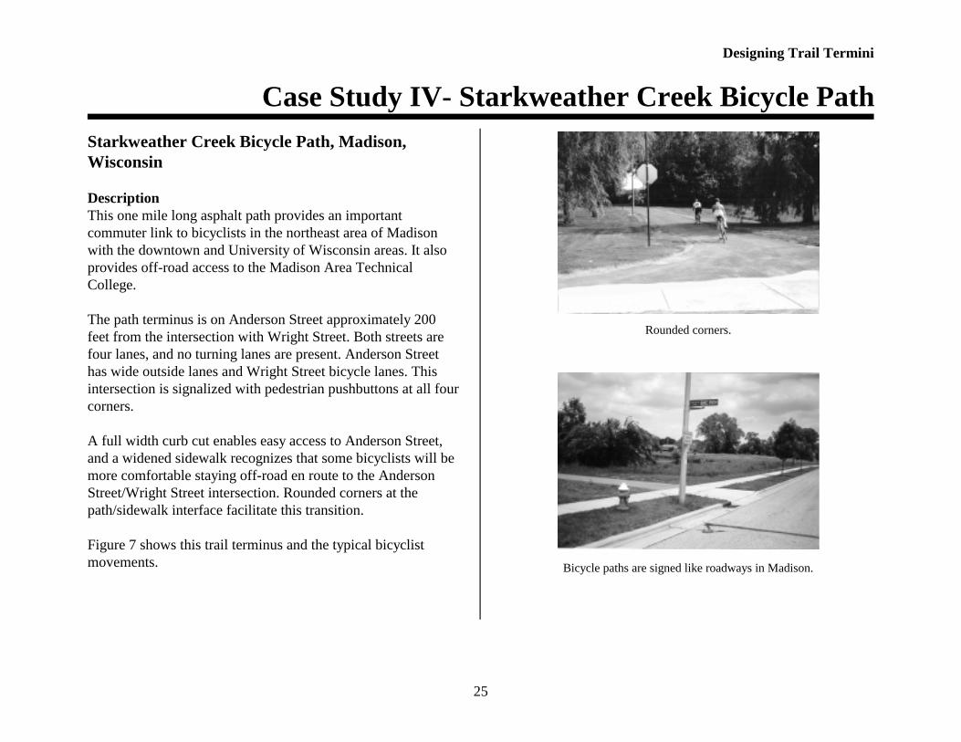
A full width curb cut enables easy access to Anderson Street,and a widened sidewalk recognizes that some bicyclists will bemore comfortable staying off-road en route to the AndersonStreet/Wright Street intersection. Rounded corners at thepath/sidewalk interface facilitate this transition.
Figure 7 shows this trail terminus and the typical bicyclistmovements.
Rounded corners.
Bicycle paths are signed like roadways in Madison.

Designing Trail Termini
Case Study IV- Starkweather Creek Bicycle Path
26
Figure 8. Starkweather Creek Bicycle Path, Madison, Wisconsin.

Designing Trail Termini
Case Study IV- Starkweather Creek Bicycle Path
27
Observations and AnalysisMost bicyclists that use the path are going to or coming fromthe Madison Area Technical College or further east onAnderson Street. The path terminus design allows the bicyclistthe choice of using the roadway or the sidewalk, though thelack of a median refuge makes using the roadway less likely.
Exiting the pathMost bicyclists turn right heading east along Anderson Streetand perform design movement À, riding on the sidepath, or Á,using the curb cut to enter the street. “Design” movement  isa vehicular style left turn, though no particular design featurefacilitates this movement for bicyclists. It is just an option.
No provisions are made for bicyclists wishing to turn left ontoAnderson Street, desire line movement Æ.
Accessing the pathBecause of the difficulty of making a left turn due to theabsence of a median refuge, desire line movement Å is notlikely. Most bicyclists approaching from the north or eastaccess the path via the widened sidewalk using movements Ãand Ä. Bicyclists approaching from the south on Wright Streetare likely to use movement Ç, a near side pedestrian style leftturn.
RecommendationsIdeally, Anderson Street should have a median refuge areaprotected by raised curbing to better enable bicyclists exitingthe path to cross and make a left turn onto Anderson Street,movement Æ. A refuge would also make accessing the trail viamovement Å more practical.Movement Ç could be assisted by providing an advance curbcut on Wright Street, essentially creating a sidewalk jug handle,to make the 90 degree turn easier to perform.
These recommended changes are shown in Figure 8.

Designing Trail Termini
Case Study IV- Starkweather Creek Bicycle Path
28
Figure 9. Starkweather Creek Path, Madison, Wisconsin. Depicted with recommended changes.

Designing Trail Termini
Case Study V- Lake Hollingsworth Trail
29
Lake Hollingsworth Trail, Lakeland, Florida.
The path encircles Lake Hollingsworth.
DescriptionThis is a 2.8 mile long, bi-directional, asphaltic surfacerecreational trail which circles Lake Hollingsworth between thelake and Lake Hollingsworth Drive. Significant numbers ofbicyclists, skaters, and pedestrians use the trail. To reduceconflicts with high speed bicyclists and other trail users, abicycle lane was constructed on the lake side only of LakeHollingsworth Drive.
Lake Hollingsworth Drive is a collector roadway with a postedspeed limit of 30 mph and ADT of 9919. Johnson Avenue wasformerly a bi-directional local street with an ADT of 2305 thathas been reconstructed as a one-way roadway with motorvehicle travel restricted to the northbound direction. Anorthbound bicycle lane and a southbound contraflow bicyclelane are provided. A street scape style sidewalk, parking, andlandscaping are also located on the right side of the roadway.Johnson Avenue provides access to the campus of FloridaSouthern College, Lake Morton, and the Lakeland PublicLibrary. Neither signal nor sign control the intersection.
Figure 9 depicts the typical movements at this unique interfaceof facilities.

Designing Trail Termini
Case Study V- Lake Hollingsworth Trail
30
Figure 10. Lake Hollingsworth Trail, Lakeland, Florida.
Designing Trail Termini
Case Study V- Lake Hollingsworth Trail
31
Observations and AnalysisExiting the trailDesign movement À gives bicyclists curb cut entrance to thebicycle lane on Lake Hollingsworth Drive. Design movementÁ directs bicyclists to the ladder crosswalk and then sidewalk.Design movement  entails a similar course, but the bicyclistproceeds from the sidewalk to the bicycle lane on JohnsonStreet. Desire line movement à is a more direct line to thebicycle lane.
Desire line movement Ä would have the bicyclist cross LakeHollingsworth Drive in the dashed bicycle lane crossing, butthis maneuver is not possible without a curb cut.
Accessing the trailDesign movement Å gives bicyclists on the LakeHollingsworth bicycle lane curb cut access to the path. Designmovement Æ entails crossing Lake Hollingsworth Drive in thedashed crossing lane from the contra-flow bicycle lane andmaking a 90 degree left turn to the bicycle lane, followed by aright turn through the curb cut. Design movement Ç involves anear side pedestrian style left turn followed by a right turn tothe ladder crosswalk and curb cut. Desire line movement È isthe natural line a bicyclist takes to enter the existing curb cut.
Desire line movement É would have the bicyclist cross directlyfrom the contra-flow lane to the path, but this maneuver is notpossible without a curb cut. Movement is a pedestrian styleleft turn and movement is a vehicular style turn followingthe more natural line.
RecommendationsThe pavement markings across Lake Hollingsworth Drive forthe bicycle lanes on Johnson Avenue indicate what would bethe efficient “design” crossing maneuvers, but the lack of curbcuts prevents direct connection to the trail. Provision of curbcuts would enable these movements, greatly simplifying andimproving bicyclist access to and egress from the path. Theexisting curb cut would then be used principally by pedestrians,improving bicyclist and pedestrian separation. Novicebicyclists may also be less inclined to ride on the JohnsonStreet sidewalk. It may be beneficial to provide pavementmarkings in the new curb cuts indicating the correct directionof travel.
Figure 10 shows the principle bicyclist movements when therecommended curb cuts and other design improvements (asfollow) are added.
The contra-flow bicycle lane is not supported by appropriatesigns or pavement markings. A R1-1 bicycle stop sign shouldbe erected to control bicyclists crossing Lake HollingsworthDrive. EXCEPT FOR BICYCLES placards should be added tothe ONE-WAY signs. Streets and major driveways alongJohnson Avenue should have WATCH FOR BICYCLES ONLEFT signs. The contra-flow bicycle lane should be separatedwith a double yellow line.
Signs on Lake Hollingsworth Drive consist of bicycle advancewarning W11-1 only. These should be augmented with W8-10placards designating the intersection as a trail crossing.

Designing Trail Termini
Case Study V- Lake Hollingsworth Trail
32
Figure 11. Lake Hollingsworth Trail, Lakeland, Florida. Depicted with recommended changes.

Designing Trail Termini
Summary
33
The crosswalk over Johnson Avenue should be the same ladderpattern as the Lake Hollingsworth Drive crosswalk. A laddercrosswalk for pedestrians should also be applied across LakeHollingsworth Drive adjacent to the bicycle lane crossing onthe west side of the intersection.
Ideally, the trail should have a larger setback from LakeHollingsworth Drive to provide storage space for queuedbicyclists trying to cross the roadway. Relocation of the trailwould also increase the separation of time between roadwayand trail conflicts that bicyclists face when accessing the trail.
The bicycle lane on Lake Hollingsworth Drive should bedashed on the approach to Johnson Avenue so as to not beoverly restrictive for bicyclists wishing to turn left in the leftturn lane. The painted median area could be re-striped as abicycle only left turn pocket for west bound riders wishing toaccess the trail.
SummaryWhile all of the of the General Guidelines listed on page two areimportant, the first one is fundamental enough to justify repeating.
Analyze the tasks of both trail users and motorists,and study the discrepancies between planned for andactual behavior. The design should take into accounttrail user desire lines.
Deviations between expected and actual behavior can be explainedtwo ways:
< the behavior intended by the designer is too complex for theuser—his skills are overestimated;
< the expected behavior is too inconvenient for the user.
Analyzing the tasks of the intended users should occur early in thedesign process and focus on trying to determine:
< the extent to which the expectations of the motorists and trailusers will correspond regarding right-of-way;
< which mistakes trail users and motorists could make; < how high the risk is that they will make these mistakes;< how serious will making a mistake be. The severity of a mistake
is largely determined by the direction, mass, and speed ofvehicles.
The significance of designing trail intersections with considerationfor trail user desire lines likewise cannot be over emphasized. Thecase studies described herein verify that trail users choose their routebased on directness and personal comfort as much as on intersectiondesign and traffic safety considerations.
The case studies demonstrate a variety of “real world” designproblems and solutions. A split trail, sidewalk, sidewalk jug handle,median, pavement marking channelization, and simple curb cuts areused to facilitate the trail-roadway interface. The studies alsoillustrate that trails are best considered as non-motorized roads usedby bicycle vehicles and pedestrians, each with their own uniquedesign user characteristics and requirements.