Embed Size (px)
Citation preview
8/3/2019 Designing Site-To-Site IPsec VPNs - Part 4
http://slidepdf.com/reader/full/designing-site-to-site-ipsec-vpns-part-4 1/16
www.NIL.com
NIL IP CORNER
Boštjan Šuštar, NIL
DESIGNING SITE-TO-SITEIPSEC VPNs - PART 4
8/3/2019 Designing Site-To-Site IPsec VPNs - Part 4
http://slidepdf.com/reader/full/designing-site-to-site-ipsec-vpns-part-4 2/16
DESIGNING SITE-TO-SITE IPSEC VPNS - PART 4by Boštjan Šuštar
Cisco IOS - IPsec Solutions
A series of articles will cover solutions using the following major implementation options with Cisco IOS routers:
z Static and dynamic crypto mapsz Point-to-point GRE tunnels over IPsecz Static and Dynamic Virtual Tunnel Interfaces (VTIs)z Dynamic Multipoint VPNs (DMVPNs)
z Group Encrypted Transport VPN (GET VPN)z Multipoint GRE tunnels over GET VPN
So far, we have covered the first three design and implementation options from the list above. This article focuses on thefourth solution in the list - Dynamic Multipoint VPNs (DMVPNs).
Dynamic Multipoint VPNs (DMVPNs)
The implementation of wide area networks (WANs) is one of the two main components in implementing enterprisenetworks (i.e., LANs interconnected through a WAN). Historically, leased lines, Time-division multiplexing (TDMs), orswitched networks (ATM and Frame Relay) were used, for which we have a very good understanding and well-known,proven design and implementation options. When deciding whether to use the Internet or MPLS VPNs for a wide areanetwork, if we want to secure the data properly in transit over the WAN, we add IPsec to the solution. To some degree,using DMVPNs mimics the older technologies, allowing us to use proven design choices (e.g., routing design), but someimportant differences need to be considered.
In essence, DMVPN is a combination of three technologies that have been around for some time: IPsec, multipoint GREtunnels and Next-Hop Resolution Protocol (NHRP). Though it is possible to implement DMVPNs just by properly combiningthese technologies, the real DMVPN includes more intelligent interaction between the technologies to improve theirperformance and simplify its implementation.
In this article, we will focus on solutions for each of the following requirements:
z Simple DMVPN. This section discusses a solution that is appropriate for small and medium-sized networks wherescalability and high performance are not requirements. Resilience is usually a requirement in most networks, however.
z DMVPN resilience. This section discusses a solution that incorporates redundancy at the head-end to improveresilience.
z DMVPN performance. This section discusses performance considerations when designing DMVPNs.z DMVPN scalability. This section presents several solutions for providing scalability and improved performance.
Simple DMVPN
In this section, we will briefly describe how DMVPNs work. Like a combination of static and a dynamic VTI, DMVPNs havethe implementation complexity of a hub-and-spoke topology. Unlike dynamic VTIs, they allow us to optimize the packetflow by building dynamic spoke-to-spoke tunnels.
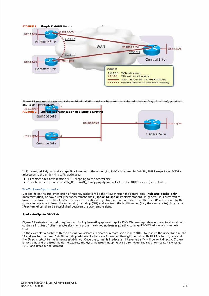
Figure 1 illustrates a simple DMVPN setup with the proper addressing separation. Notice that the inner DMVPN addresses
on the multipoint GRE tunnel are taken from a /24 subnet.
Copyright © 2009 NIL Ltd. All rights reserved.
Doc. No. IPC-0209
1/13
8/3/2019 Designing Site-To-Site IPsec VPNs - Part 4
http://slidepdf.com/reader/full/designing-site-to-site-ipsec-vpns-part-4 3/16
Figure 2 illustrates the nature of the multipoint GRE tunnel – it behaves like a shared medium (e.g., Ethernet), providingany-to-any connectivity.
In Ethernet, ARP dynamically maps IP addresses to the underlying MAC addresses. In DMVPN, NHRP maps inner DMVPNaddresses to the underlying WAN addresses:
z All remote sites have a static NHRP mapping to the central site.z Remote sites can learn the VPN_IP-to-WAN_IP mapping dynamically from the NHRP server (central site).
Traffic Flow Optimization
Depending on the implementation of routing, packets will either flow through the central site (hub-and-spoke-only
implementation) or flow directly between remote sites (spoke-to-spoke implementation). In general, it is preferred tohave traffic take the optimal path. If a packet is destined to go from one remote site to another, NHRP will be used by thesource remote site to learn the underlying next-hop (NH) address from the NHRP server (i.e., the central site). A dynamic
IPsec tunnel can then be established between the two remote sites.
Spoke-to-Spoke DMVPNs
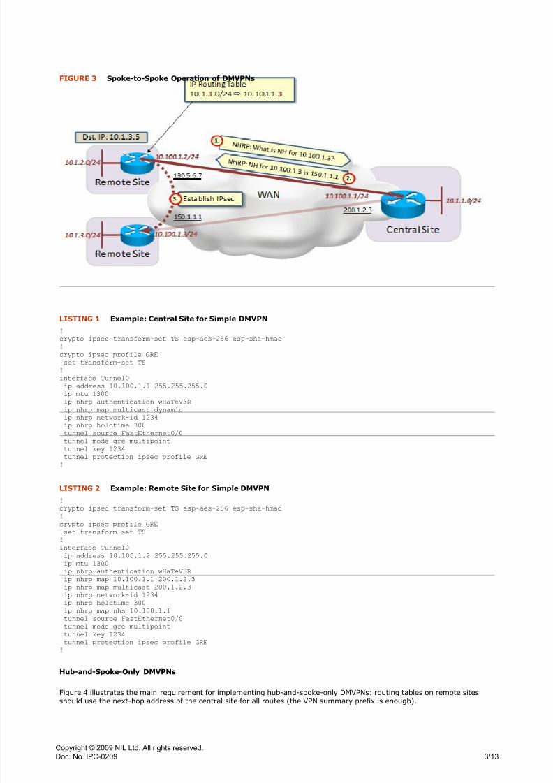
Figure 3 illustrates the main requirement for implementing spoke-to-spoke DMVPNs: routing tables on remote sites shouldcontain all routes of other remote sites, with proper next-hop addresses pointing to inner DMVPN addresses of remotesites.
In the example, a packet with the destination address in another remote site triggers NHRP to resolve the underlying publicIP address for the inner DMVPN next-hop address. Packets are forwarded through the hub while NHRP is in progress andthe IPsec shortcut tunnel is being established. Once the tunnel is in place, all inter-site traffic will be sent directly. If thereis no traffic and the NHRP holdtime expires, the dynamic NHRP mapping will be removed and the Internet Key Exchange(IKE) and IPsec tunnel deleted.
FIGURE 1 Simple DMVPN Setup
FIGURE 2 Logical Representation of a Simple DMVPN
Copyright © 2009 NIL Ltd. All rights reserved.
Doc. No. IPC-0209
2/13
8/3/2019 Designing Site-To-Site IPsec VPNs - Part 4
http://slidepdf.com/reader/full/designing-site-to-site-ipsec-vpns-part-4 4/16
!
crypto ipsec transform-set TS esp-aes-256 esp-sha-hmac
!
crypto ipsec profile GRE
set transform-set TS
!
interface Tunnel0
ip address 10.100.1.1 255.255.255.0
ip mtu 1300
ip nhrp authentication wHaTeV3R
ip nhrp map multicast dynamicip nhrp network-id 1234
ip nhrp holdtime 300
tunnel source FastEthernet0/0
tunnel mode gre multipoint
tunnel key 1234
tunnel protection ipsec profile GRE
!
!
crypto ipsec transform-set TS esp-aes-256 esp-sha-hmac
!
crypto ipsec profile GRE
set transform-set TS
!
interface Tunnel0ip address 10.100.1.2 255.255.255.0
ip mtu 1300
ip nhrp authentication wHaTeV3R
ip nhrp map 10.100.1.1 200.1.2.3
ip nhrp map multicast 200.1.2.3
ip nhrp network-id 1234
ip nhrp holdtime 300
ip nhrp map nhs 10.100.1.1
tunnel source FastEthernet0/0
tunnel mode gre multipoint
tunnel key 1234
tunnel protection ipsec profile GRE
!
Hub-and-Spoke-Only DMVPNs
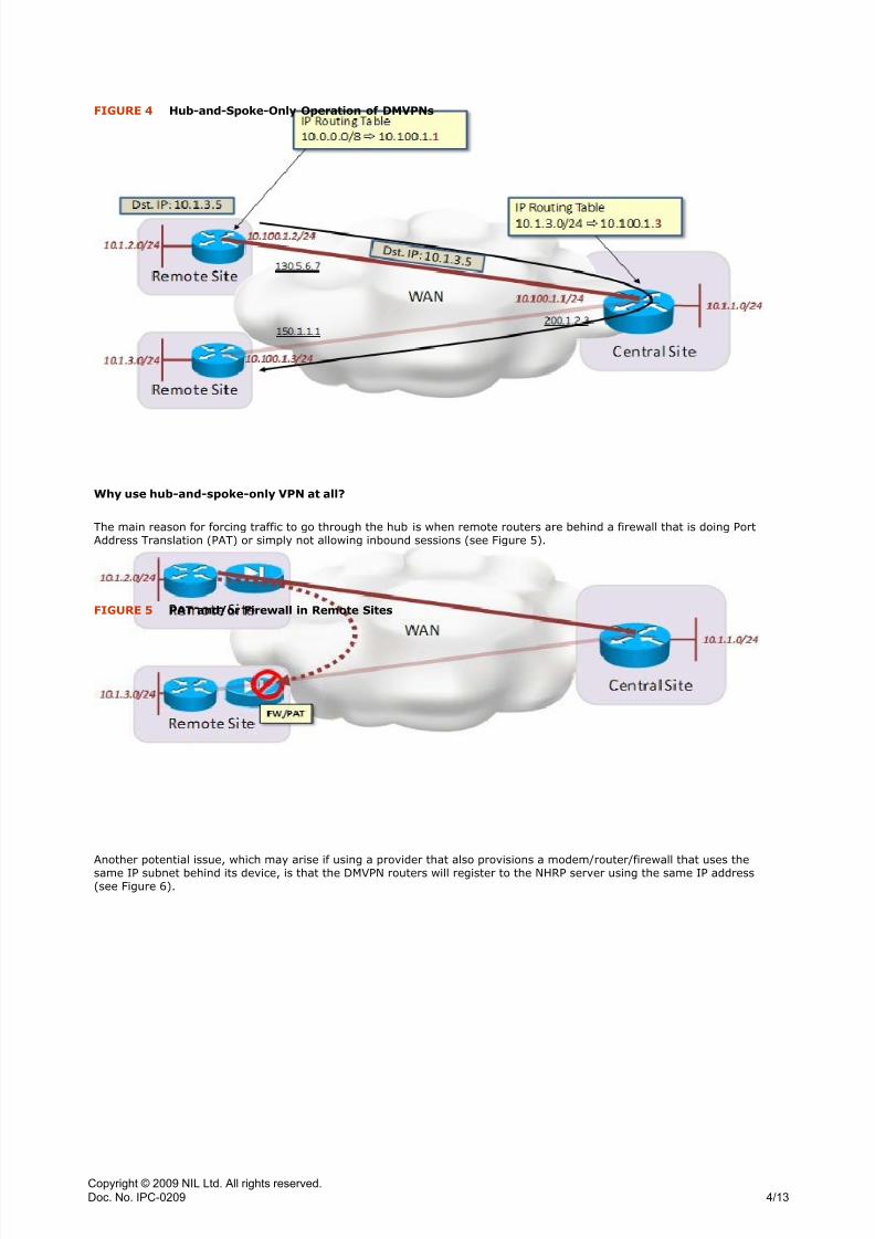
Figure 4 illustrates the main requirement for implementing hub-and-spoke-only DMVPNs: routing tables on remote sitesshould use the next-hop address of the central site for all routes (the VPN summary prefix is enough).
FIGURE 3 Spoke-to-Spoke Operation of DMVPNs
LISTING 1 Example: Central Site for Simple DMVPN
LISTING 2 Example: Remote Site for Simple DMVPN
Copyright © 2009 NIL Ltd. All rights reserved.
Doc. No. IPC-0209
3/13
8/3/2019 Designing Site-To-Site IPsec VPNs - Part 4
http://slidepdf.com/reader/full/designing-site-to-site-ipsec-vpns-part-4 5/16
Why use hub-and-spoke-only VPN at all?
The main reason for forcing traffic to go through the hub is when remote routers are behind a firewall that is doing PortAddress Translation (PAT) or simply not allowing inbound sessions (see Figure 5).
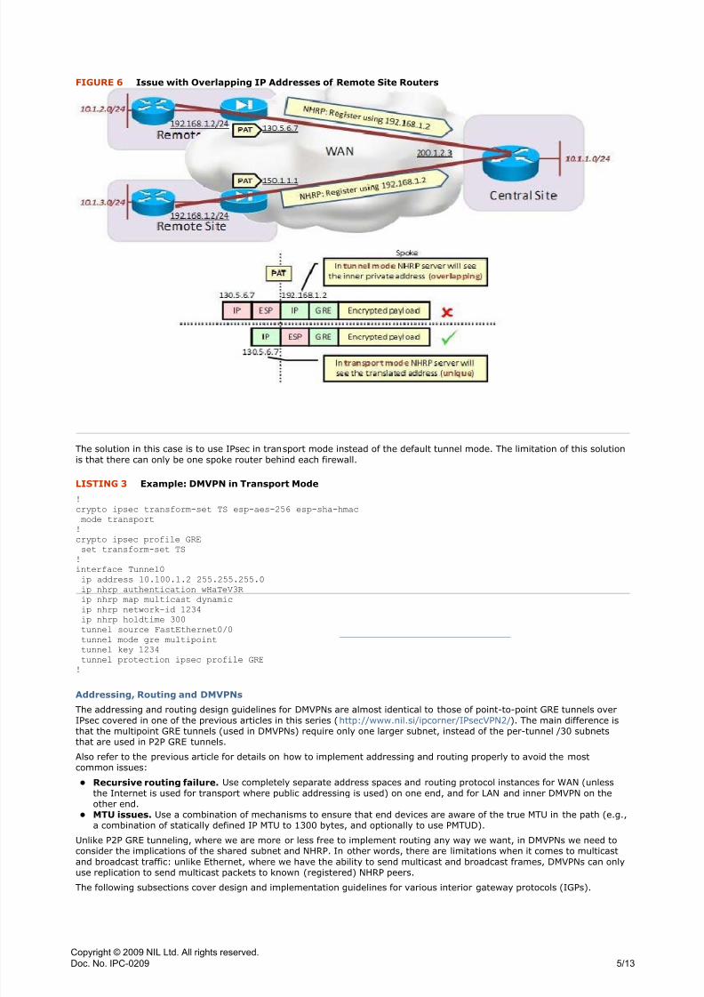
Another potential issue, which may arise if using a provider that also provisions a modem/router/firewall that uses thesame IP subnet behind its device, is that the DMVPN routers will register to the NHRP server using the same IP address(see Figure 6).
FIGURE 4 Hub-and-Spoke-Only Operation of DMVPNs
FIGURE 5 PAT and/or Firewall in Remote Sites
Copyright © 2009 NIL Ltd. All rights reserved.
Doc. No. IPC-0209
4/13
8/3/2019 Designing Site-To-Site IPsec VPNs - Part 4
http://slidepdf.com/reader/full/designing-site-to-site-ipsec-vpns-part-4 6/16
The solution in this case is to use IPsec in transport mode instead of the default tunnel mode. The limitation of this solutionis that there can only be one spoke router behind each firewall.
!
crypto ipsec transform-set TS esp-aes-256 esp-sha-hmac
mode transport
!
crypto ipsec profile GRE
set transform-set TS
!
interface Tunnel0
ip address 10.100.1.2 255.255.255.0
ip nhrp authentication wHaTeV3R
ip nhrp map multicast dynamic
ip nhrp network-id 1234
ip nhrp holdtime 300
tunnel source FastEthernet0/0
tunnel mode gre multipoint
tunnel key 1234
tunnel protection ipsec profile GRE
!
Addressing, Routing and DMVPNsThe addressing and routing design guidelines for DMVPNs are almost identical to those of point-to-point GRE tunnels overIPsec covered in one of the previous articles in this series (http://www.nil.si/ipcorner/IPsecVPN2/). The main difference isthat the multipoint GRE tunnels (used in DMVPNs) require only one larger subnet, instead of the per-tunnel /30 subnetsthat are used in P2P GRE tunnels.
Also refer to the previous article for details on how to implement addressing and routing properly to avoid the mostcommon issues:
z Recursive routing failure. Use completely separate address spaces and routing protocol instances for WAN (unlessthe Internet is used for transport where public addressing is used) on one end, and for LAN and inner DMVPN on theother end.
z MTU issues. Use a combination of mechanisms to ensure that end devices are aware of the true MTU in the path (e.g.,a combination of statically defined IP MTU to 1300 bytes, and optionally to use PMTUD).
Unlike P2P GRE tunneling, where we are more or less free to implement routing any way we want, in DMVPNs we need toconsider the implications of the shared subnet and NHRP. In other words, there are limitations when it comes to multicastand broadcast traffic: unlike Ethernet, where we have the ability to send multicast and broadcast frames, DMVPNs can only
use replication to send multicast packets to known (registered) NHRP peers.The following subsections cover design and implementation guidelines for various interior gateway protocols (IGPs).
FIGURE 6 Issue with Overlapping IP Addresses of Remote Site Routers
LISTING 3 Example: DMVPN in Transport Mode
Copyright © 2009 NIL Ltd. All rights reserved.
Doc. No. IPC-0209
5/13
8/3/2019 Designing Site-To-Site IPsec VPNs - Part 4
http://slidepdf.com/reader/full/designing-site-to-site-ipsec-vpns-part-4 7/16
Using RIP in DMVPNs
Although RIP version 2 is simple and fast, it may not be the most appropriate choice for all DMVPN solutions:
z Only one process is allowed, making it difficult to separate the VPN routing from the WAN routing (not a problem if theInternet is used for transport).
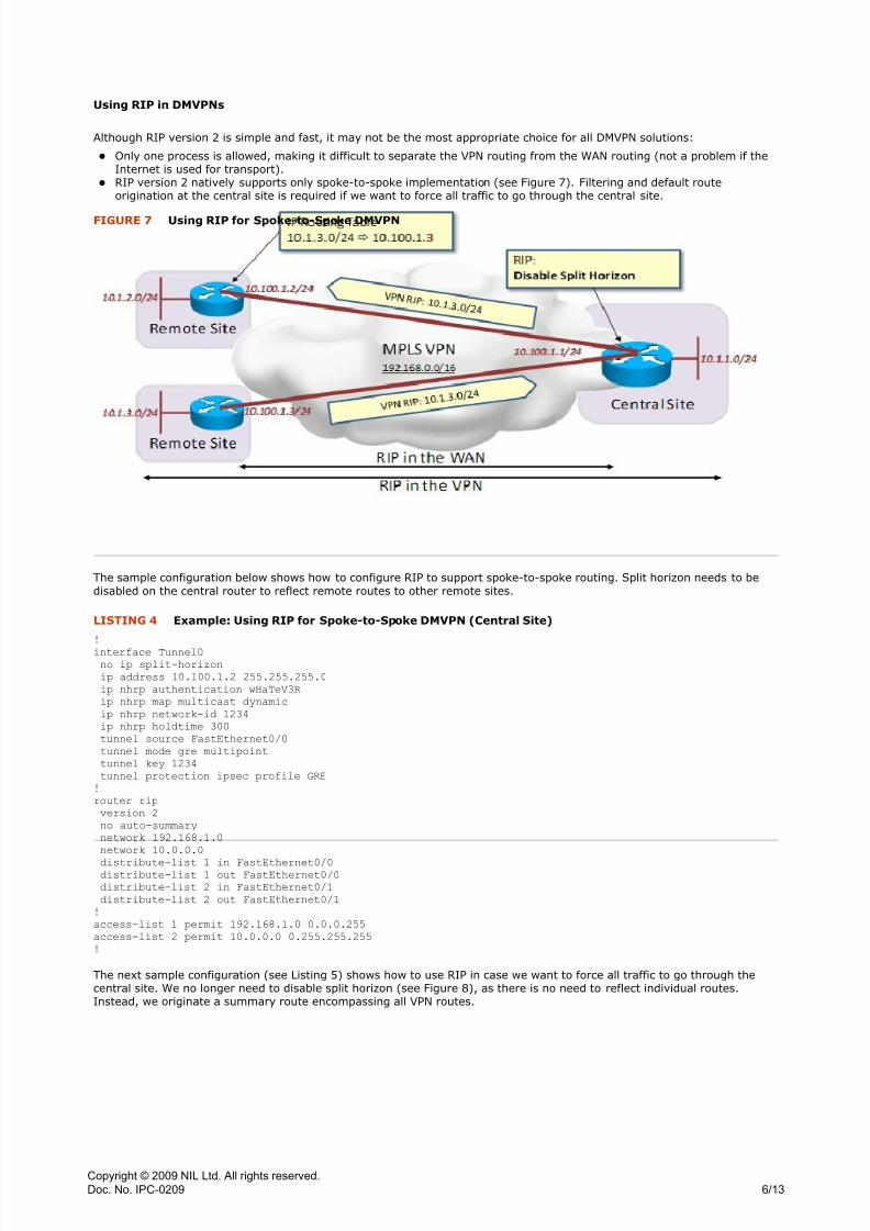
z RIP version 2 natively supports only spoke-to-spoke implementation (see Figure 7). Filtering and default routeorigination at the central site is required if we want to force all traffic to go through the central site.
The sample configuration below shows how to configure RIP to support spoke-to-spoke routing. Split horizon needs to bedisabled on the central router to reflect remote routes to other remote sites.
!
interface Tunnel0
no ip split-horizon
ip address 10.100.1.2 255.255.255.0
ip nhrp authentication wHaTeV3R
ip nhrp map multicast dynamic
ip nhrp network-id 1234
ip nhrp holdtime 300
tunnel source FastEthernet0/0
tunnel mode gre multipoint
tunnel key 1234
tunnel protection ipsec profile GRE
!
router rip
version 2
no auto-summary
network 192.168.1.0
network 10.0.0.0
distribute-list 1 in FastEthernet0/0distribute-list 1 out FastEthernet0/0
distribute-list 2 in FastEthernet0/1
distribute-list 2 out FastEthernet0/1
!
access-list 1 permit 192.168.1.0 0.0.0.255
access-list 2 permit 10.0.0.0 0.255.255.255
!
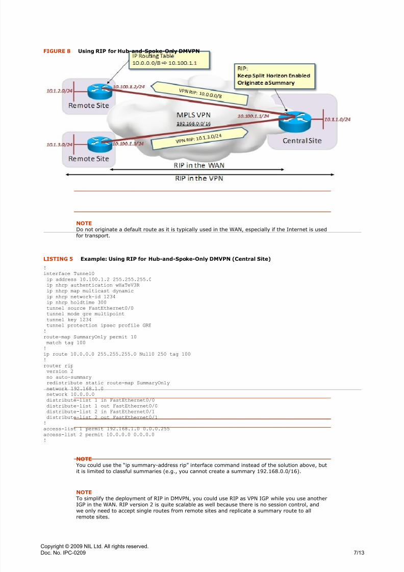
The next sample configuration (see Listing 5) shows how to use RIP in case we want to force all traffic to go through thecentral site. We no longer need to disable split horizon (see Figure 8), as there is no need to reflect individual routes.Instead, we originate a summary route encompassing all VPN routes.
FIGURE 7 Using RIP for Spoke-to-Spoke DMVPN
LISTING 4 Example: Using RIP for Spoke-to-Spoke DMVPN (Central Site)
Copyright © 2009 NIL Ltd. All rights reserved.
Doc. No. IPC-0209
6/13
8/3/2019 Designing Site-To-Site IPsec VPNs - Part 4
http://slidepdf.com/reader/full/designing-site-to-site-ipsec-vpns-part-4 8/16
NOTEDo not originate a default route as it is typically used in the WAN, especially if the Internet is usedfor transport.
!
interface Tunnel0
ip address 10.100.1.2 255.255.255.0
ip nhrp authentication wHaTeV3R
ip nhrp map multicast dynamic
ip nhrp network-id 1234
ip nhrp holdtime 300tunnel source FastEthernet0/0
tunnel mode gre multipoint
tunnel key 1234
tunnel protection ipsec profile GRE
!
route-map SummaryOnly permit 10
match tag 100
!
ip route 10.0.0.0 255.255.255.0 Null0 250 tag 100
!
router rip
version 2
no auto-summary
redistribute static route-map SummaryOnly
network 192.168.1.0
network 10.0.0.0
distribute-list 1 in FastEthernet0/0distribute-list 1 out FastEthernet0/0
distribute-list 2 in FastEthernet0/1
distribute-list 2 out FastEthernet0/1
!
access-list 1 permit 192.168.1.0 0.0.0.255
access-list 2 permit 10.0.0.0 0.0.0.0
!
NOTEYou could use the “ip summary-address rip” interface command instead of the solution above, butit is limited to classful summaries (e.g., you cannot create a summary 192.168.0.0/16).
NOTE
To simplify the deployment of RIP in DMVPN, you could use RIP as VPN IGP while you use anotherIGP in the WAN. RIP version 2 is quite scalable as well because there is no session control, andwe only need to accept single routes from remote sites and replicate a summary route to allremote sites.
FIGURE 8 Using RIP for Hub-and-Spoke-Only DMVPN
LISTING 5 Example: Using RIP for Hub-and-Spoke-Only DMVPN (Central Site)
Copyright © 2009 NIL Ltd. All rights reserved.
Doc. No. IPC-0209
7/13
8/3/2019 Designing Site-To-Site IPsec VPNs - Part 4
http://slidepdf.com/reader/full/designing-site-to-site-ipsec-vpns-part-4 9/16
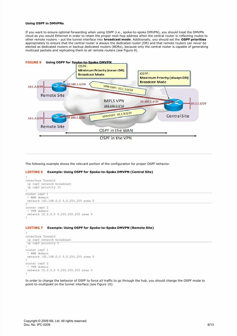
Using OSPF in DMVPNs
If you want to ensure optimal forwarding when using OSPF (i.e., spoke-to-spoke DMVPN), you should treat the DMVPNcloud as you would Ethernet in order to retain the proper next-hop address when the central router is reflecting routes toother remote routers – put the tunnel interface into broadcast mode. Additionally, you should set the OSPF prioritiesappropriately to ensure that the central router is always the dedicated router (DR) and that remote routers can never beelected as dedicated routers or backup dedicated routers (BDRs), because only the central router is capable of generatingmulticast packets and replicating them to all remote routers (see Figure 9).
The following example shows the relevant portion of the configuration for proper OSPF behavior.
!interface Tunnel0
ip ospf network broadcast
ip ospf priority 10
!
router ospf 1
! WAN domain
network 192.168.0.0 0.0.255.255 area 0
!
router ospf 2
! VPN domain
network 10.0.0.0 0.255.255.255 area 0
!
!
interface Tunnel0ip ospf network broadcast
ip ospf priority 0
!
router ospf 1
! WAN domain
network 192.168.0.0 0.0.255.255 area 0
!
router ospf 2
! VPN domain
network 10.0.0.0 0.255.255.255 area 0
!
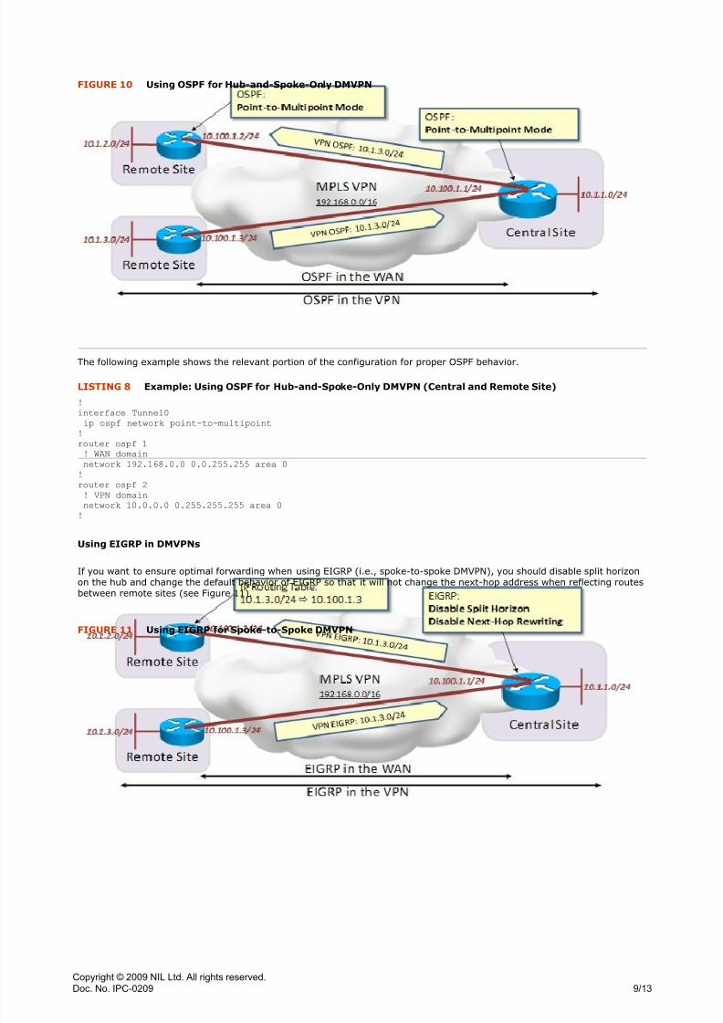
In order to change the behavior of OSPF to force all traffic to go through the hub, you should change the OSPF mode topoint-to-multipoint on the tunnel interface (see Figure 10).
FIGURE 9 Using OSPF for Spoke-to-Spoke DMVPN
LISTING 6 Example: Using OSPF for Spoke-to-Spoke DMVPN (Central Site)
LISTING 7 Example: Using OSPF for Spoke-to-Spoke DMVPN (Remote Site)
Copyright © 2009 NIL Ltd. All rights reserved.
Doc. No. IPC-0209
8/13
8/3/2019 Designing Site-To-Site IPsec VPNs - Part 4
http://slidepdf.com/reader/full/designing-site-to-site-ipsec-vpns-part-4 10/16
The following example shows the relevant portion of the configuration for proper OSPF behavior.
!
interface Tunnel0
ip ospf network point-to-multipoint
!
router ospf 1
! WAN domain
network 192.168.0.0 0.0.255.255 area 0
!
router ospf 2
! VPN domain
network 10.0.0.0 0.255.255.255 area 0
!
Using EIGRP in DMVPNs
If you want to ensure optimal forwarding when using EIGRP (i.e., spoke-to-spoke DMVPN), you should disable split horizonon the hub and change the default behavior of EIGRP so that it will not change the next-hop address when reflecting routesbetween remote sites (see Figure 11).
FIGURE 10 Using OSPF for Hub-and-Spoke-Only DMVPN
LISTING 8 Example: Using OSPF for Hub-and-Spoke-Only DMVPN (Central and Remote Site)
FIGURE 11 Using EIGRP for Spoke-to-Spoke DMVPN
Copyright © 2009 NIL Ltd. All rights reserved.
Doc. No. IPC-0209
9/13
8/3/2019 Designing Site-To-Site IPsec VPNs - Part 4
http://slidepdf.com/reader/full/designing-site-to-site-ipsec-vpns-part-4 11/16
The following example shows the relevant portion of the configuration for proper EIGRP behavior.
!
interface Tunnel0
no ip split-horizon eigrp 2
no ip next-hop-self eigrp 2
!
router eigrp 1
! WAN domain
no auto-summary
network 192.168.0.0 0.0.255.255
!
router eigrp 2
! VPN domain
no auto-summary
network 10.0.0.0
!
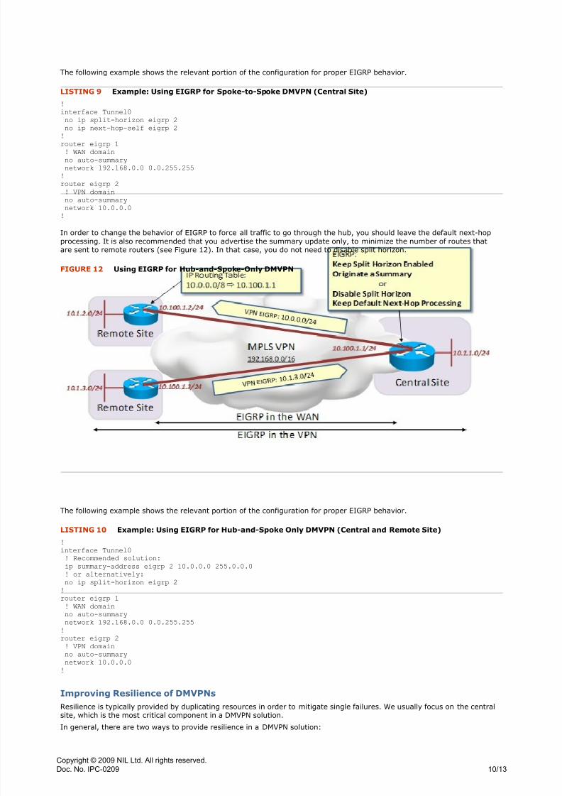
In order to change the behavior of EIGRP to force all traffic to go through the hub, you should leave the default next-hopprocessing. It is also recommended that you advertise the summary update only, to minimize the number of routes thatare sent to remote routers (see Figure 12). In that case, you do not need to disable split horizon.
The following example shows the relevant portion of the configuration for proper EIGRP behavior.
!
interface Tunnel0
! Recommended solution:ip summary-address eigrp 2 10.0.0.0 255.0.0.0
! or alternatively:
no ip split-horizon eigrp 2
!
router eigrp 1
! WAN domain
no auto-summary
network 192.168.0.0 0.0.255.255
!
router eigrp 2
! VPN domain
no auto-summary
network 10.0.0.0
!
Improving Resilience of DMVPNsResilience is typically provided by duplicating resources in order to mitigate single failures. We usually focus on the centralsite, which is the most critical component in a DMVPN solution.
In general, there are two ways to provide resilience in a DMVPN solution:
LISTING 9 Example: Using EIGRP for Spoke-to-Spoke DMVPN (Central Site)
FIGURE 12 Using EIGRP for Hub-and-Spoke-Only DMVPN
LISTING 10 Example: Using EIGRP for Hub-and-Spoke Only DMVPN (Central and Remote Site)
Copyright © 2009 NIL Ltd. All rights reserved.
Doc. No. IPC-0209
10/13
8/3/2019 Designing Site-To-Site IPsec VPNs - Part 4
http://slidepdf.com/reader/full/designing-site-to-site-ipsec-vpns-part-4 12/16
z Redundant hub router in a DMVPN cloud where two routers are configured as NHRP servers, thus allowing remoterouters to switch over to a secondary hub in case the first one becomes unreachable. The downside of this solution isthat it may result in poor performance during failures (e.g., remote sites try to contact the first NHRP server before therequests time out, thus taking some time to get NHRP mappings; load balancing is more difficult to implement becausethere are two gateways on the same subnet).
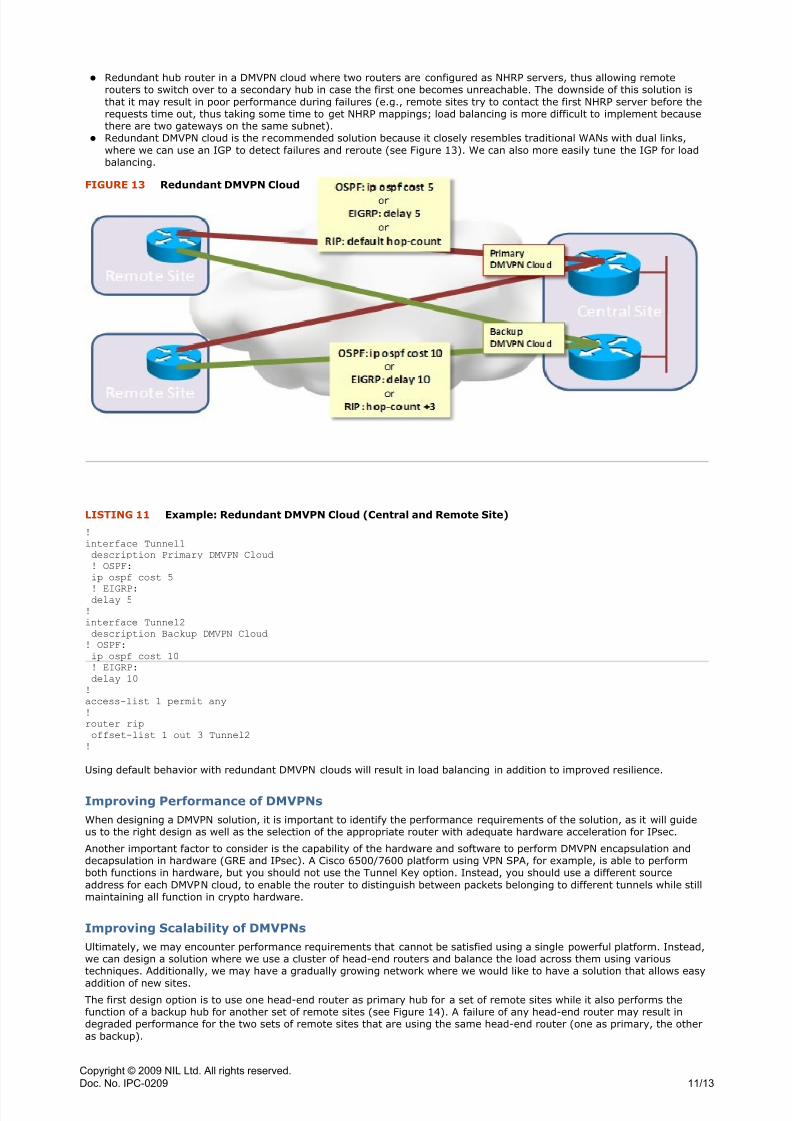
z Redundant DMVPN cloud is the recommended solution because it closely resembles traditional WANs with dual links,where we can use an IGP to detect failures and reroute (see Figure 13). We can also more easily tune the IGP for loadbalancing.
!
interface Tunnel1
description Primary DMVPN Cloud
! OSPF:
ip ospf cost 5
! EIGRP:delay 5
!
interface Tunnel2
description Backup DMVPN Cloud
! OSPF:
ip ospf cost 10
! EIGRP:
delay 10
!
access-list 1 permit any
!
router rip
offset-list 1 out 3 Tunnel2
!
Using default behavior with redundant DMVPN clouds will result in load balancing in addition to improved resilience.
Improving Performance of DMVPNs
When designing a DMVPN solution, it is important to identify the performance requirements of the solution, as it will guideus to the right design as well as the selection of the appropriate router with adequate hardware acceleration for IPsec.
Another important factor to consider is the capability of the hardware and software to perform DMVPN encapsulation anddecapsulation in hardware (GRE and IPsec). A Cisco 6500/7600 platform using VPN SPA, for example, is able to performboth functions in hardware, but you should not use the Tunnel Key option. Instead, you should use a different sourceaddress for each DMVPN cloud, to enable the router to distinguish between packets belonging to different tunnels while stillmaintaining all function in crypto hardware.
Improving Scalability of DMVPNs
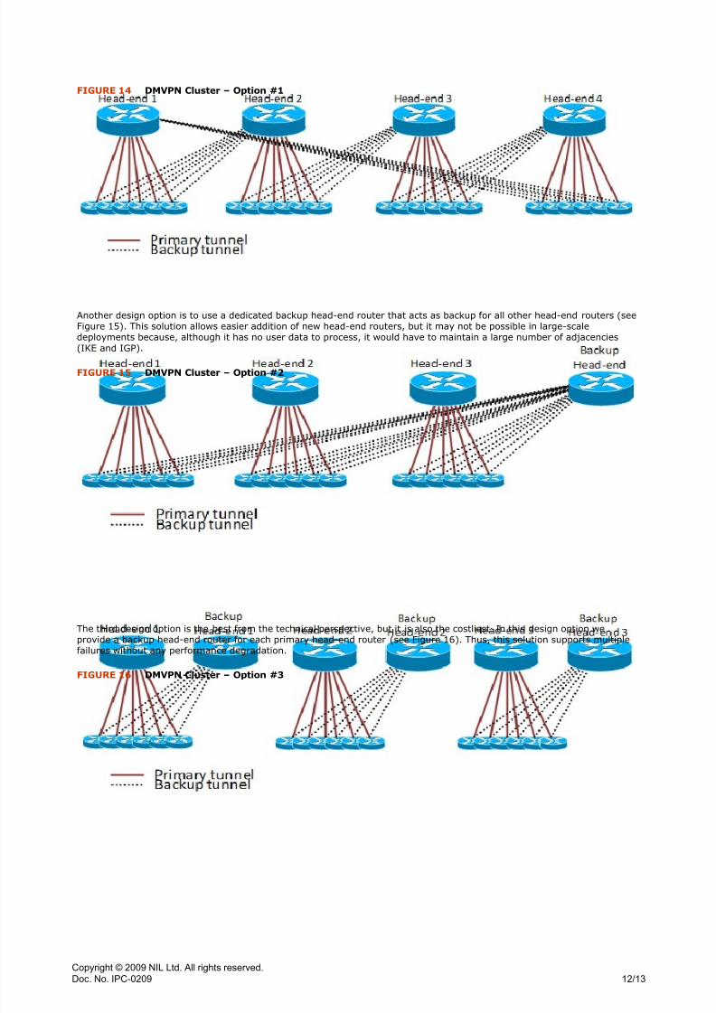
Ultimately, we may encounter performance requirements that cannot be satisfied using a single powerful platform. Instead,we can design a solution where we use a cluster of head-end routers and balance the load across them using varioustechniques. Additionally, we may have a gradually growing network where we would like to have a solution that allows easy
addition of new sites.The first design option is to use one head-end router as primary hub for a set of remote sites while it also performs thefunction of a backup hub for another set of remote sites (see Figure 14). A failure of any head-end router may result indegraded performance for the two sets of remote sites that are using the same head-end router (one as primary, the otheras backup).
FIGURE 13 Redundant DMVPN Cloud
LISTING 11 Example: Redundant DMVPN Cloud (Central and Remote Site)
Copyright © 2009 NIL Ltd. All rights reserved.
Doc. No. IPC-0209
11/13
8/3/2019 Designing Site-To-Site IPsec VPNs - Part 4
http://slidepdf.com/reader/full/designing-site-to-site-ipsec-vpns-part-4 13/16
Another design option is to use a dedicated backup head-end router that acts as backup for all other head-end routers (seeFigure 15). This solution allows easier addition of new head-end routers, but it may not be possible in large-scaledeployments because, although it has no user data to process, it would have to maintain a large number of adjacencies(IKE and IGP).
The third design option is the best from the technical perspective, but it is also the costliest. In this design option weprovide a backup head-end router for each primary head-end router (see Figure 16). Thus, this solution supports multiplefailures without any performance degradation.
FIGURE 14 DMVPN Cluster – Option #1
FIGURE 15 DMVPN Cluster – Option #2
FIGURE 16 DMVPN Cluster – Option #3
Copyright © 2009 NIL Ltd. All rights reserved.
Doc. No. IPC-0209
12/13
8/3/2019 Designing Site-To-Site IPsec VPNs - Part 4
http://slidepdf.com/reader/full/designing-site-to-site-ipsec-vpns-part-4 14/16
The limitation of all three solutions is that spoke-to-spoke tunnels are only possible between remote sites that are using thesame hub. It is therefore recommended to group remote sites logically if possible (e.g., geographically collocated sites mayhave more direct traffic than distant remote sites).
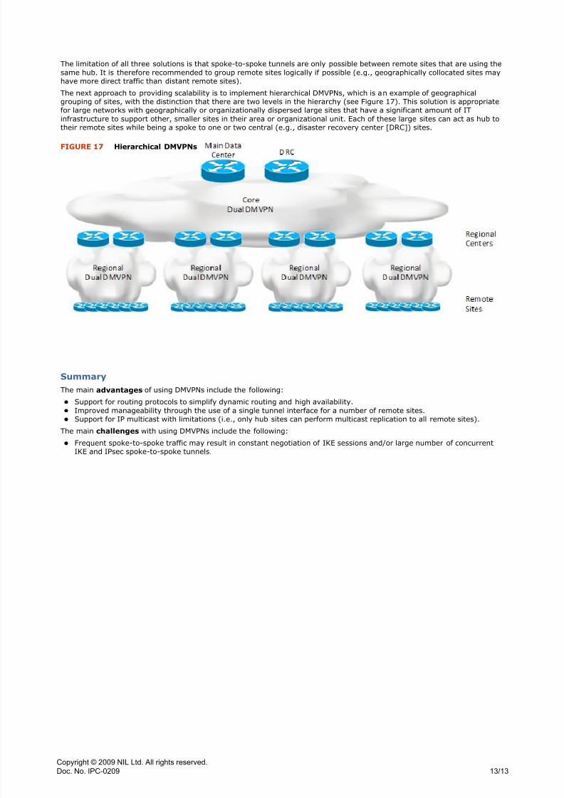
The next approach to providing scalability is to implement hierarchical DMVPNs, which is an example of geographicalgrouping of sites, with the distinction that there are two levels in the hierarchy (see Figure 17). This solution is appropriatefor large networks with geographically or organizationally dispersed large sites that have a significant amount of ITinfrastructure to support other, smaller sites in their area or organizational unit. Each of these large sites can act as hub totheir remote sites while being a spoke to one or two central (e.g., disaster recovery center [DRC]) sites.
Summary
The main advantages of using DMVPNs include the following:
z Support for routing protocols to simplify dynamic routing and high availability.z Improved manageability through the use of a single tunnel interface for a number of remote sites.z Support for IP multicast with limitations (i.e., only hub sites can perform multicast replication to all remote sites).
The main challenges with using DMVPNs include the following:
z Frequent spoke-to-spoke traffic may result in constant negotiation of IKE sessions and/or large number of concurrentIKE and IPsec spoke-to-spoke tunnels.
FIGURE 17 Hierarchical DMVPNs
Copyright © 2009 NIL Ltd. All rights reserved.
Doc. No. IPC-0209
13/13

8/3/2019 Designing Site-To-Site IPsec VPNs - Part 4
http://slidepdf.com/reader/full/designing-site-to-site-ipsec-vpns-part-4 15/16
ABOUT NIL
NIL is one of the leading European data communications service-oriented groups of companies, focusing on the
high-value segments in the Service Provider and Enterprise data networking market. NIL offers a full range of
services, including consulting, design and implementation of large networks, assistance in network operation,
and associated advanced training.
NIL exploits the full potential of the Internet in delivering the most sophisticated standard and tailored training
solutions to customers worldwide. From traditional instructor-led training to virtual classrooms, web-based
training and hands-on remote labs on the Internet, our learning solutions fit all learning styles, schedules,
personal needs and preferences, geography, and time zones.
Being a Cisco Learning Solutions Partner (CLSP) for more than ten years, NIL is part of the industry's best
network of data communications training companies. We have developed and delivered specialized advanced
internetworking courses to the most demanding and advanced customers worldwide.
NIL’s customers include Service Providers, large and medium sized corporations, banks, financial and
governmental institutions worldwide.
For more information about NIL solutions and services, visit www.NIL.com.
Further Information
For more useful technical articles, visit www.NIL.com/ipcorner.
More NIL IP Corner Articles

8/3/2019 Designing Site-To-Site IPsec VPNs - Part 4
http://slidepdf.com/reader/full/designing-site-to-site-ipsec-vpns-part-4 16/16
NIL Data Communications
Tivolska cesta 48
SI-1000 Ljubljana, Slovenia
www.NIL.com
NIL Data Communications
UOB Plaza 1, 80 Raffles Place
Singapore 048624
www.NIL.com
NIL Data Communications Services
Spechtgasse 2 a
2353 Guntramsdorf, Austria
www.NIL.com
NIL America Inc.
P.O. Box 52349
Riverside, CA 92517
USA
www.NIL.com