Embed Size (px)
Citation preview

DESIGNING SHELTER IN NEW BUILDINGS
A manual for Architects on the preliminary
designing of shielding from fallout gammaradiation in normally functioning spaces in
new buildings.
written for
The Office of Civil Defense
Department of Defense
CONTRACT NO. OCD-PS-64-252 ^fl'
AST DIVISION
/i 720by
Albert Knott
a*
Shelter Research and Study Program
Department of Architectural Engineering
The Pennsylvania State University
University Park, Pennsylvania
CO
March 1967


ABSTRACT
This manual discusses radiation shielding as it applies to the preliminary desigr
of protection against fallout gamma radiation in new construction. The archit
tural principles of shielding are discussed at length and designing examples an
given. Planning charts are presented whereby material weights can be selecte
a preliminary basis to provide shielding which will satisfy the Office of Civil [
requirements for Community Shelters. Environmental control, shelter supply, *
management factors are not discussed as they are auxiliary to the problem of tl
provision of radiation protection.
It is anticipated that the preliminary architectural schemes developed through
use of this manual will be verified by skilled analysts before final designs are
pleted.
ACKNOWLEDGEMENT
The assistance of Mr. Larry O. Sinkey for development of the computer progra
which were used to generate the data from which the planning charts were dra
and of Mr. Thomas B. Brown for the presentation of the illustrations, is gratefi
acknowledged. Appreciation is also extended to Mr. Richard E. Kummer, Mr
Robert Sprankle, and Mrs. Joan Brooks for editorial and production assistance,
Sincere appreciation is extended to the architects and engineers who allowed
buildings or competition entries to be used as examples in this manual. Their
are listed with the examples.

TABLE OF CONTENTS
DESIGNING OF SHELTER IN NEW BUILDINGS
The Architect 1
The Fallout Shelter 1
Shelter Design 2
The National Fallout Protection Problem 3
Fallout 3
Radioactivity 3
Radiation and Architecture 4
Protection Factor 6
Radiation Contributions 7
Roof Contribution 8
Ground Contributions 8
Ground-Direct Radiation 9
Wai I -Scattered Radiation .
'
9
Skyshine Radiation 10
Protection From Radiation 11
Geometric Shielding 11
Barrier Shielding 11
Normal Shelter Configurations 12
The Ground Floor Case 12
The Basement Case 15
The Aboveground Shelter (The Multistory Case) 17
Use of the Planning Charts 17
Chart Limitations 19
The Principles of Shelter Design 23
Details 29
Deficiencies in Design 31
Examples of Design Using the Charts 32
Case 1 , A One-Story School 32
Case 2, A Multistory Building 35
Shelter Planning Discussion and Summary 38
The Analogy 38
The Design Charts 39
Summary 40
Design Charts 40
Appendix 75HT__L l D ! j.- c c_ll t CL_U ii

DESIGNING SHELTER IN NEW BUILDINGS
THE ARCHITECT
The architect can be defined as that designer
who, through his specialized training and
ability, can most efficiently and creativelydetermine the environment in which man can
live and function. The definition is extended,for the purpose of this manual, to include the
environment of fallout gamma radiation as
well as the normal environments of wind, rain,
and sun. This manual has been written to pro-vide the architect with the information neces-
sary to design radiation protection into build-
ings as he now designs protection from the ele-
ments. This manual discusses preliminafy
designing.
THE FALLOUT SHELTER
Architects have .recognized that any building
offers protection from fallout radiation. Some
buildings provide adequate protection. Others
provide protection which is less than adequate,The architect can use his creativity to provide
adequate protection within all buildings.*
Protection must be incorporated without jeop-
ardizing the appearance, the normal function
of the building, or the cost. The judicious
choice of building materials, and the special
arrangement of the building spaces to enhance
radiation protection, are the essence of the
architectural design problem for fa 1 1 out shelters,
The architect is to select the shape and mate-
rials of a building so that spaces are created
in which people can find adequate protection

2.
from fallout radiation. Since, hopefully, the
need for radiation protection will never arise,
many clients may feel they cannot afford to
incorporate high level shelter which will
adversely affect the function or cost of the
building. The architect is, therefore, chal-
lenged with the problem of providing ade-
quate radiation protection, without sacrific-
ing the normal design requirements. Shelter
must be incorporated as integral, multi-use
space satisfying fully the primary purpose of
the building.
SHELTER DESIGN
Schematic architectural design is the develop-ment of an architectural concept, simultane-
ously considering the interrelated parts of the
problem*. It is the initial stage of any archi-
tectural design development.
Shelter design, a facet of architectural design,
is the design of a building within which ade-
quate protection from fallout radiation is to
be provided. It is to be emphasized that if
shelter is to be provided, without a signifi-
cant increase in cost, and without adversely
affecting the function or beauty of the build-
ing, it must be considered in the schematic
design stage of the architectural design and
must be an integral part of the building con-
cept included as a program requirement. It
must also be a secondary function, subser-
vient to the primary function for which the
space is intended.
It is the purpose of this presentation to discuss
the concepts of shelter and the mechanics of
shelter design for radiation protection. Guidelines and simplified procedures will be pre-sented to enable architects to make properbasic decisions regarding shelter during the
P>

3.
THE NATIONAL FALLOUT PROTECTION PROBLEM
in i m
The Nation must tackle its problems in the
sequence of their importance and relative
ease of solution. For example, if a nuclear
attack should occur, the problem of fallout
will be widespread. The provision of protec-tion from fallout radiation is relatively sim-
ple and can be inexpensive as will be seen in
the text that follows. The problem of pro-tection from thermal radiation and blast des-
truction, however, may be extreme in tar-
geted areas, and expensive and difficult to
solve. Since millions of people in the United
States will need only fallout protection, that
can be obtained at relatively low cost, fallou
radiation shielding is emphasized in national
policy.
Fallout
If a nuclear device is detonated on or near
the ground a great amount of earth and other
materials will be vaporized in the extreme
heat and will mix with the radioactive mate-
rials from the bomb. As this vapor mixture is
carried into the cooler air of high altitudes,
it condenses. Minute radioactive particles
cling to the surfaces of the condensed debris.
They soon become heavy enough to descend
to earth, downwind, sometimes many miles
from the point of explosion. Thus, radioactiv
fallout is spread across the land.
The debris, fine to medium particles, will
settle on exposed surfaces, on streets, roofs,
lawns, farms, reservoirs,, It will drift. It
may be washed or wiped away, plowed under,
tracked in, swept out.
Radioactivity
Radioactivity is the spontaneous emission of
energy from the bomb's unstable atoms which

4.
These rays can damage living tissue. A per-son may become ill when exposed to suffi-
cient radiation, because of the number of
damaged cells in his body. An excessive
amount of damaged tissue of the body mayresult in death after several days.
As time passes, radiation is emitted from the
unstable or radioactive atoms, resulting in
atoms of a stable or at least a more nearlystable form. Thus as the number of unstable
atoms reduces, the radiation level of the
field of fallout decreases. This decrease in
intensity is at first quite rapid, later less
rapid.
for every seven-fold increase in time, there
is approximately a ten-fold decrease in radia-
tion intensity. If the radiation intensity level
one hour after the explosion is taken as the
starting point, at the end of seven hours the
intensity of radiation will have decreased ten-
fold or to 10% of the original. In seven times
seven hours or 49 hours (2 days) later it will
be down another ten-fold or to 1% of the origi-
nal, and in two weeks (7 times 2 days) the
radiation will be one-tenth of l%of its value
at the starting point. Thus radiation decreases
rapidly in the first two weeks; but as time
goes on, the decrease is much slower.
Shelter occupants can emerge when the radia-
tion intensity drops to biologically acceptablelevels. Although some areas may receive lit-
tle or no fallout, most required shelter occu-
pancy periods will be from two days to twoweeks in duration. Others may have to
remain protected for extended periods of time.
/0o
intense
( during eo.r/y
RADIATION AND ARCHITECTURE
It has been indicated that the unstable atomic
particles in fallout emit bundles of energy
including gamma rays. These rays are the

5.
A useful analogy in understanding radiation
and the effect architectural facilities have
upon it, is to say that each particle of fallout
is a tiny but powerful flashing light. These
tiny lights flash intermittently, shining their
tiny, piercing beams each time in a randomlydifferent direction. Thus a field of fallout
might appear to an observer as a vast city at
night would appear to a passenger on a plane.The lights of this analogous city would each
be blinking rapidly on and off, shooting darts
of light off into the night air.
In relation to these fields of flashing light
rays, all matter would be analogous to
clouded glass. Lights can be seen through
relatively thin clouded-glass sheets, analo-
gous to the way radiation can be "seen"
through lightweight partitions, roofs, and
walls. As the wall (the panel of clouded
glass) becomes thicker, less light is trans-
mitted directly and more light is scattered
and diffused. As the building envelopebecomes massive, the light is nearly all
absorbed, and the room becomes quite dark.
This would correspond to a high degree of
fallout radiation protection. It is to be noted
that gamma radiation is actually not visible
and that it can penetrate all materials, no
matter how dense. Do not assume that if youcannot see the fallout you will not receive
radiation. We assume only for the sake of
our analogy that it can be seen.
Even the soil is clouded glass. Thus each
analogous building may be envisioned as a
full-sized, clouded-glass structure set on a
plain of clouded glass. Sheets of tiny flash-
ing lights would lie on the roof, window
sills, and on the ground. As the wind blows,
these tiny lights would move and drift, piling
up against curbs as sand will drift across a

4.
These rays can damage living tissue. A per-son may become ill when exposed to suffi-
cient radiation, because of the number of
damaged cells in his body. An excessive
amount of damaged tissue of the body mayresult in death after several days.
As time passes, radiation is emitted from the
unstable or radioactive atoms, resulting in
atoms of a stable or at least a more nearlystable form. Thus as the number of unstable
atoms reduces, the radiation level of the
field of fallout decreases. This decrease in
intensity is at first quite rapid, later less
rapid.
for every seven-fold increase in time, there
is approximately a ten-fold decrease in radia-
tion intensity. If the radiation intensity level
one hour after the explosion is taken as the
starting point, at the end of seven hours the
intensity of radiation will have decreased ten-
fold or to 10% of the original . In seven times
seven hours or 49 hours (2 days) later it will
be down another ten-fold or to 1% of the origi-
nal, and in two weeks (7 times 2 days) the
radiation will be one-tenth of l%of its value
at the starting point. Thus radiation decreases
rapidly in the first two weeks; but as time
goes on, the decrease is much slower.
Shelter occupants can emerge when the radia-
tion intensity drops to biologically acceptablelevels. Although some areas may receive lit-
tle or no fallout, most required shelter occu-
pancy periods will be from two days to two
weeks in duration. Others may have to
remain protected for extended periods of time.
RADIATION AND ARCHITECTURE
It has been indicated that the unstable atomic

5.
A useful analogy in understanding radiation
and the effect architectural facilities have
upon it, is to say that each particle of fallout
is a tiny but powerful flashing light. These
tiny lights flash intermittently, shining their
tiny, piercing beams each time in a randomlydifferent direction. Thus a field of fallout
might appear to an observer as a vast city at
night would appear to a passenger on a plane.The lights of this analogous city would each
be blinking rapidly on and off, shooting darts
of light off into the night air.
In relation to these fields of flashing light
rays, all matter would be analogous to
clouded glass. Lights can be seen through
relatively thin clouded-glass sheets, analo-
gous to the way radiation can be "seen"
through lightweight partitions, roofs, and
walls. As the wall (the panel of clouded
glass) becomes thicker, less light is trans-
mitted directly and more light is scattered
and diffused. As the building envelopebecomes massive, the light is nearly all
absorbed, and the room becomes quite dark.
This would correspond to a high degree of
fallout radiation protection. It is to be noted
that gamma radiation is actually not visible
and that it can penetrate all materials, no
matter how dense. Do not assume that if youcannot see the fallout you will not receive
radiation. We assume only for the sake of
our analogy that it can be seen.
Even the soil is clouded glass. Thus each
analogous building may be envisioned as a
full -sized, clouded-glass structure set on a
plain of clouded glass. Sheets of tiny flash-
ing lights would lie on the roof, window
sills, and on the ground. As the wind blows,
these tiny lights would move and drift, piling
up against curbs as sand will drift across a
road.

6.
Although these lights are tiny, their darting
rays are extremely penetrating. In the living
room of a normal suburban home made of our
clouded glass, the brightness would be still
about half as great as it would be outside in
the field of lights. We say the room has a
"protection factor" of two (2), as the outside
light intensity has been reduced by a factor
of two by the materials of which the house is
made.
If we were in the central corridor on, say,
the sixth floor of a twelve-story modern
apartment house, the area would be rela-
tively dark. The light intensity might be
only about one fiftieth (1/50), of the light
intensity down below on the street, or Pf 50.
Note that if the observer were standing on
the twelfth floor, it would be quite bright,
due to the light shining down through the
roof material from the fallout lying on the
roof. Similarly the ground floor level would
be well lit due to the fallout radiation shin-
ing through the walls, windows, and doors at
street level.
Suffice it to say, the less "bright" the build-
ing space is, the greater protection it offers
against fallout gamma radiation. Below
ground basements under multistory buildings
are usually excellent.
Protection Factor
Any space within a building provides its occu-
pants some measure of protection against fall-
out radiation. As building materials absorb
and diffuse incoming rays of radiation, the
level of exposure inside the building will be
less than that outside. As the occupant is
surrounded by building material, no matter
how light weight it may be, he receives some
protection.tTflUTiimiimTiiniiiiint

1 1I 1
imumiiiidii
Contribution
(ground Contribution
It is convenient to discuss the exposure levels
quantitatively. The degree of radiation reduc-
tion of architectural spaces is given by the
single above-mentioned term "protection fac-
tor." If a building occupant receives one
tenth (1/10) of the radiation which he would
have received had he been standing on a
smooth horizontal plane outside of the build-
ing with fallout evenly distributed everywherearound him, his protection factor is said to be
ten (10). If the shape, size, and materials
of a building reduce the level of exposure in
one of its interior spaces to one part in one
hundred (1/100), the protection factor of
that space is said to be one hundred (100).
Hence, the higher the protection factor,
the better the shelter.
Representative values may be as shown in the
sketches shown to the left. Protection factor
is abbreviated as PF.
Radiation Contributions
Protection factors are computed by trained
analysts by calculating the "contributions"
from the various sources of radiation. Radia-
tion will come from the fallout lying on the
roof. This radiation is called the roof con-
tribution, its amount being dependent on the
size, shape, and location of the roof and the
weight of the materials used in its construc-
tion.
Ground contribution is the amount of radia-
tion entering the shelter through the walls
and openings, having come from the fallout
lying on the ground. Together with the roof
contribution it makes up the majority of the
radiation received. Radiation contributions
from fallout lying on foliage, on window
sills, canopies and the like, together with
that tracked in, or brought in through unpro-tected or unfiltered ventilation air intakes,
make up the remainder of the radiation of
concern to the architect.

These radiation contributions are expressed
in per cent. For example, if a shelter
occupant receives 20 per cent (1/5) of the
total radiation outside the building, he
has a protection factor of 5. Likewise, if
he receives 2.5 per cent (1/40) of the
total outside radiation, he has PF 40.
Roof Contribution. To continue the discus-
sion of radiation, the writer will return to the
clouded-glass analogy and the fields of tiny
lights. Considering the roof construction as
a sheet of clouded glass, it occupies the same
area with respect to the sheltered space as
does the field of tiny flashing lights it sup-
ports. The light diffuses down through the
roof and bathes the room in a general glow.An observer looking upward would note that
the roof surface directly overhead was con-
siderably lighter than areas more distantly
removed. If he held his arms extended over
his head and encompassed the area of greatest
brightness, his arms would be pointed about
45 degrees down from directly overhead. This
is the area of greatest roof contribution and
is of major concern to the designer.
If the roof were increased in weight in this
area directly overhead, the greatest reduction
in radiation (light) would be made for the low-
est increase in total weight of construction
materials. This would probably result in the
lowest possible construction cost.
It is to be noted that the light does not comefrom the peripheral areas of the roof as easilyas from directly overhead. It has a greaterslant thickness of roof material down throughwhich to pass and greater distance to travel.
Ground Contributions. The second basic
type of contribution mentioned above was

Sc Altered i^
in turn will be broken up into three categoriedirect radiation, wall scattered radiation, an<
skyshine.
Ground-Direct Radiation. In a clouded-
glass house made analogous to normal masonryschool or residential construction, the walls
would be still transparent enough for some of
the light to shine directly from the outside
field of lights into the shelter space. This
light would enter on a line-of-sight path fromthe fallout particles, through the walls andinto the shelter. It would be reduced in inter
sity due to the normal absorption of the wall
material but would not be altered in its course
This is ground direct radiation.
Ground-direct radiation can first be greatlyreduced by placing the shelter spaces in the
below-ground areas of building interiors, (1),
thus "ducking under" the incoming gammaradiation. Second (2) and third (3) means of
avoiding ground-direct radiation are to placethe shelter in an inner core at ground level,or in the central areas of upper floors, several
floors above the street. The first method, the
basement location, requires the rays to passdown through the dense, clouded-glass soil to
gain access to the shelter. The second requinthe ground-direct radiation to come in hori-
zontally through a series of wails and interior
partitions, while the third method requiresthe harmful rays to come up through several
floor layers, diminishing by natural absorptiorbefore gaining access to the designated shelte
areas.
Wall-Scattered Radiation. The second form o
ground contribution of concern to architects i:
wall -scattered radiation. As gamma rays entcthe galaxy of atomic particles which make upthe construction materials of a building, the
opportunity for collision occurs. Just as thewall absorbs radiation by direct collision, so
can radiation be scattered by near misses or
by ricocheting.

10.
The technical descriptions of the various
forms of interaction between gamma radia-
tion and the molecular particles of construc-
tion materials are not of concern to the archi-
tect. Since material can allow the passage
of energy as ground-direct radiation, or
absorb or scatter radiation as described by
collision, we have a sufficient concept for
the design of architectural shelter spaces.
We will use the analogy that as diffused light
providing a general glow will occur in our
clouded-glass structure, so will scattered
radiation enter an architectural shelter space.
As diffused and scattered light will enter a
room' by devious routes, so will gamma radia-
tion find its way through .barrier after barrier
and into sheltered spaces.
Skyshine Radiation. Air is composed of mole-
cules of gas, particles of haze, droplets of
moisture, and dust. Radiation will scatter by
collision with these particles. Radiation enter-
ing the shelter, after having scattered in air,
is called "skyshine."
As an example of the relative intensity of this
air-scattered radiation, skyshine, a person
standing alone in a vast plain of fallout would
receive about 90% of the radiation from the
ground as ground-direct, and about 10% from
above as skyshine.
It is also interesting to note that if he were
standing in an open excavation, duckingdown below the field of fallout, he would
receive only skyshine, and that being a con-
tribution of 10% or one part in ten, his pro-tection factor would be 10. As the Civil
Defense requirement is PF 40, he is well on
his way to protection before the architect
has an opportunity to place him in a building.It is for such reasons as this that the state-
ment is made, that all construction, no mat-ter how simple, offers some degree of radia-
tion protection.
qfoond dire^T'
30/
1 1 u i ii 1 1 1 nrn"
ladiaijon

11.
PROTECTION FROM RADIATION
Protection is obtained by geometry and barrier
Geometric Shielding
Radiation intensity reduces with distance; this
is one of the characteristics which validates
the clouded-glass structure analogy. The far-
ther away the source of radiation is, the less
radiation the shelter occupant will receive.
Thus, a house or a building provides a "clearei
area" in which the shelter occupant can stand,
and holds a layer of fallout at a distance over-
head. As the fields of fallout lie at some dis-
tance from the person, some radiation protect!*
is afforded. The overall level of radiation ex-
posure may be cut down in this fashion by as
much as a factor or two or more.
Barrier Shielding
The second means of obtaining protection is by
placing mass (dense material) between the fall
out and shelterees.
As indicated by the clouded-glass analogy,construction material (matter) will interfere
with the passage of radiation. The "light"
in the analogy will be reduced in intensity by
absorption, and by diffusion or scattering.
Thus construction material will (1) allow some
radiation to pass on through (direct), (2) cause
some radiation to change direction (wall-
scatter), and (3) absorb some radiation com-
pletely. Thus, the atomic particles of which
the material is made will either allow the ray:
of energy to pass among them, will lie in the
path causing collision and scattering, or will
block the path causing collision and complete
absorption. The heavier the material the great
the probability of absorption.
12.
It is with these two characteristics, geometry
and barrier, that the architect must create
protection in new construction.
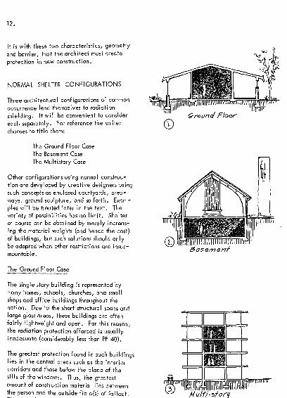
NORMAL SHELTER CONFIGURATIONS
Three architectural configurations of common
occurrence lend themselves to radiation
shielding. It will be convenient to consider
each separately. For reference the writer
chooses to title them:
The Ground Floor Case
The Basement Case
The Multistory Case
Other configurations using normal construc-
tion are developed by creative designers using
such concepts as enclosed courtyards, area-
ways, ground sculpture, and so forth. Exam-
ples will be treated later in the text. The
variety of possibilities has no limit. Shelter
of course can be obtained by merely increas-
ing the material weights (and hence the cost)
of buildings, but such solutions should onlybe adopted when other restrictions are insur-
mountable.
The Ground Floor Case
The single story building is represented by
many homes, schools, churches, and small
shops and office buildings throughout the
nation. Due to the short structural spans and
large glass areas, these buildings are often
fairly lightweight and open. For this reason,the radiation protection afforded is usually
inadequate (considerably less than PF 40).
The greatest protection found 5n such buildingslies in the central areas such as the interior
corridors and those below the plane of the
sills of the windows. Thus, the greatestamount of construction material lies betweenthe person and the outside field(s) of fallout.
MlllllllllllllllWIimiinn?

13.
ecfion
_j.i
Plan
interior corridor occupant must pass throughthe exterior walls, through such furniture,book cases, and normal furnishings as mayhave been in the way, and through the inte-
rior partitions. This series of barriers is thus
instrumental in reducing the radiation expo-sure.
To utilize this shielding characteristic of mod-ern building, locate normal building functions
usable by shelter occupants (and hence which
facilitate shelter occupancy) in the central
areas. Large rooms house the most people.
Toilets, food preparation facilities, school
libraries, and public utility control areas sup-
port shelter occupancy, k building, squarein plan, is a more effective shield than a longthin building. Thus large rooms placed in the
"core" or central areas of square buildings and
surrounded by such service functions as toilets
and kitchens provide the best shelter in one-
story buildings.
A narrow interior corridor with a heavy wall
provides the greatest protection from roof con-
tribution because a comparatively large
amount of the radiation must pass obliquelydown through the corridor walls before enter-
ing the shelter. Thus a weakness of our pre-
vious solution of large core area shelters
comes to light. The larger the interior core
space, the larger the roof contribution.
Locate the shelter centrally to minimize
ground contribution, then make the room
large enough to house large numbers of people.
This centrally located shelter is thus placed
in the most disadvantageous location as far as
roof contribution is concerned, and the walls
are pushed back allowing roof radiation to
enter without passing through the interior par-
titions.
It is to be noted that a large interior room has
very little more roof radiation than does a
medium-large room. Recall that most of the

root radiation reaches us from almost directly
overhead. Therefore unless the walls are
quite close to us, they will not interfere with
this major contribution. An interior audito-
rium or gymnasium in a school will not allow
very much more radiation to enter than will
a classroom. To reduce roof contribution
appreciably, the walls must be as near as,
say, those found in the corridors between
classrooms. Recall that, if we hold our hands
up at 45 degrees pointing to the ceiling,
most of the roof radiation comes from within
this cone.
The roof radiation problem leads to the next
logical change in shelter configuration. As
a single story building must have a relatively
heavy roof (see the charts. shown later in this
text), it is often more economical to use con-
struction of two or more stories. Hence,rather than titling this discussion "The Single
Story Case," it is called the "Ground Floor
Case." By placing several overhead floor
and roof barriers between the shelter occupantand the fallout lying on the roof, the radia-
tion entering the shelter from above is appre-
ciably reduced.
Thus a shelter in, say a two-story school., can
be located in the first floor corridors with
some degree of success. Normal construction,
if judiciously selected as to material weightand location, can provide a protection factor
of forty .
It has been noted that radiation exposure is
greatest to shelter occupants when the shelter
is located in single-story buildings of normal
construction. To provide a protection factor
of forty, both the roof construction and wall
construction must be heavy and hence seldom
normal. Inajmostall cases, fairly massive
construction will have to be used. With ref-
erence to our clouded-glass structure analogy,the weights of the walls will have to be
increased to cut down on the intense light
\V
cone, s/a/>5
/fi
C/a$sroom floor*
&-, -
on
liyhhaejoht roof /2.block 52.
concrete, tees
IS p*f

//he of Are.
Pmustscdrfer To
coming from the ground, and either a heavyroof or a series of light floors and a roof will
have to be placed overhead to cut down on
the roof radiation. When our space becomes
quite gloomy, we have eliminated enough
light. When our structure becomes quite
heavy or quite complex, utilizing a series of
barriers, we have eliminated enough fallout
radiation.
In summary, a shelter on the ground floor must
have an appreciably greater amount of mate-rial (mass) between it and the fields of radia-
tion. This may consist of either single, heavywalls and a heavy roof, or a series of lighter
encompassing walls and overhead roofs, total-
ing the same weight as the single barriers.
The actual weights required can be found in
the planning charts starting on page 41, andwill be discussed later in the text.
The Basement Case
The second, simplest, most effective, and
usually lowest cost configuration for provid-
ing shelter in modern construction is the base-
ment. The shelter occupant has been placedunder the "line of fire" of radiation from fall-
out lying on the ground outside, and beneath
at least one overhead floor and roof. Thus
ground radiation must enter the shelter after
having scattered at least once (in the air out-
side or in the ground floor exterior wall) and
after having passed through two barriers (the
outside wall and the overhead floor). The
radiation contribution from the roof will have
passed through the roof and the overhead
floor(s).
The weight of material between the shelter
occupant and the fallout on the roof must be
90 pounds per square foot if no radiation is
received from the ground. It will be seen
from the charts that, if the overhead floor
weighs 70 pounds per square foot (psf) and the

roof weighs 30 pounds per square foot, the
designer may make the ground floor walls,
partitions, and windows of any weight and
size he wishes and still have a PF 40 shelter
in the basement. Seventy pounds per squarefoot is equivalent to five and one-half inches
of concrete. Note should be taken that the
required weights are considerably below those
for a ground floor shelter.
Shelter can also be developed in basements by
placing the occupants in basement corridors
and using an overhead barrier weighing less
than 70 psf . The corridor walls intercept not
only the ground radiation coming in after hav-
ing scattered in the exterior walls above, but
also intercept some of the radiation comingfrom the roof. Thus, although the corridor
ceiling must still weigh 70 psf, the remaining
portions of the basement ceiling may be
reduced in weight. A reasonable decision
would be to reduce the required basement
ceiling weight by an amount equal to the
weight (psf) of the added corridor walls.
It is interesting to note that one of the stan-
dard Civil Defense home shelter, made by
constructing a brick box in the corner of the
basement, is merely a variation of the base-
ment corridor concept.
Exposed basements, in which a portion of the
basement wall extends above the surface of
the ground, are common. In such designs,
protection is reduced and compensation must
be provided by increasing the walls of the
shelter. As radiation can enter the shelter
with a minimum amount of scattering, its
energy is not effectively dissipated, and
heavy walls must be used.
In situations where it becomes necessary to
utilize exposed basement walls in shelter plan-
ning, the ground floor chart values may be
used to determine the required wall weight of
the exposed portions.
^ f> roof
f ^10 f*f. S/oar
See. cAarts /,* 43
/s may/ / ' J.L
cleared tvtth a
\\ i 1 1 1 *i i *in *f *y 'j'* g
bosemcnf corridor '(_ 5 fruc/ura./
exposedr(bad)
non-e?rpo^eci

The Aboveground Shelter (The Multistory Case)
shelter
f center
portions)
Multistory ca.se
The third and final type of shelter to be con-
sidered is the protected space found in the
interior portions of the upper floors of multi-
story buildings. These spaces are in full view
of the fields of radiation, but are surrounded
by many natural barriers. Several floors nor-
mally lie between the shelter occupant and
the fallout on the ground outside. Several
overhead barriers lie between the occupantand the roof. Partitions shield the spacesfrom fallout scattering from the exterior walls,
from skyshine, or from that coming directly in
from the distant ground.
It will be noted from the planning charts that
the most exposed aboveground shelters are
those which are located either near the groundor immediately below the roof. This is logical.
As in the clouded-glass structure analogy,these would be the well-lit spaces. The most
protected areas are the interior spaces of the
middle stories. It will be noted from the plan-
ning charts that normal construction is usually
adequate.
USE OF THE PLANNING CHARTS
The charts are designed to read alike. The
arrows on the diagrams on page 18 indicate
the sequences permissible. Any three values
of the variables will indicate the fourth
required to give a protection factor of forty
(40).
On the Ground Floor Shelter and AbovegroundShelter charts, the four characteristics which
are necessary to specify the degree of radia-
tion protection are given. These are (1) the
per cent of the exterior wall perimeter occu-
pied by doors and windows, (2) the weight of
the exterior wall in pounds per square foot (psf),
(3) the total weight of the overhead construc-
tion through which radiation from the fallout

Ib.
on the roof must pass, again in pounds per
square foot (psf), and (4) the total weight
(psf) of interior partitions through which the
ground contribution must pass. These are
arranged so that if any three are given, the
fourth may be determined. The combinations
are such that the protection factor anywherewithin the shelter is at least forty.
To work an example, assume a multistory
building of, say, 8 stones, each floor of
which is a 2 1/2 inch concrete slab on corru-
gated steel decking. Each floor (and roof)
weighs 40 pounds per square foot. Protection
in the fourth floor corridors is requested.
The total overhead weight is five barriers at
40 psf each, or 200 psf. If. the area of each
floor is approximately 10,000 square feet
there is sufficient information with which to
enter chart 14. Turn to chart 14 on page 64.
Note that it is for a fourth floor, interior
shelter in a 10,000 square foot building.
The windows (chosen for architectural reasons)
start 36 inches above the floor level and
extend to the 7-foot level . The charts were
developed assuming that the windows start at
the three foot level and extend to the ceiling.
The difference will have a negligible effect
on our solution. Fifty per cent of the peri-
meter of the building at the fourth floor level
is window, the remainder being composed of
precast concrete panels weighing 30 pounds
per square foot.
Enter the chart and read in accordance with
the sketched directions shown on the next
page. The answer found is that an interior
partition weighing at least 42 pounds per
square foot is necessary all around the shelter
to meet the Civil Defense requirement for
minimum radiation protection, PF 40. A 4-
inch hollow block wall, plastered both sides,
will satisfy the requirement.
the charts (choose any 2>
a.nd look up the fourth).
/) n|.u
Mj-jy-J^
JllXlL.LlLtlrDJ"]lt^
40
1~htt fourth floor
a
} 4

19.
-sf> inferiorvJft.ll
Prt- Cast Wall -- pUsttnK/ partition
S.)4" frrick on &1
concrete. iot)f
S
vTTW : 4o)
.
-
weight.)
Note that if an unplastered 4-inch block wall
is desired for architectural reasons (4-inch
block weighs 30 psf), an exterior wall weigh-
ing from 55 to 60 pounds per square foot is
required.
Note also that the original choice of a 30 psf
exterior wall and a 42 psf interior partition
totals 72 pounds per square foot, while the
second choice totals 60 plus 30, or 90 pounds
per square foot. In multistory buildings,
lightweight exterior walls reduce the amount
of radiation scattering in, hence reduce the
total amount of wall barrier required to meet
the criterion.
The radiation absorption characteristics of the
wall also enter in. Note that if the wall
weighs 140 psf, no interior partition is required.
Thus it is seen that the use of the charts is
quite simple. The architect chooses three of
the four variables and looks up the fourth,
which will give him a PF of 40.
In the Basement Shelter Case the four varia-
bles are different, although the mechanics of
chart reading are the same. The four varia-
bles are the wall unit weight, the window
perimeter ratio for the floor above, the total
overhead weight (exclusive of the weight of
the floor immediately over the basement),
and finally, the unit weight of the basement
ceiling construction itself.
CHART LIMITATIONS
The charts are intended to provide quantita-
tive data for preliminary design only. Theywill enable the architect to make reasonable,
preliminary choices which must later be veri-
fied or refined by a staff member trained in
shelter analysis.

The charts give exact answers for conditions
which duplicate the design chart assumptions,
These are as follows:
1 . The shelter is centrally located
within the building and occupies one
third of the floor area. (The charts
will give reasonably close answers for
any size of shelter located anywherewithin the building. If a wall of the
shelter is also an exterior wall that
wall should be the weight indicated
by the chart using an interior parti-
tion weight of zero).
2. The buildings are assumed to be
rectangular. (The charts give reason-
ably correct answers up to a length to
width ratio of 5 to 1 . The values
given would be unconservative for
very thin buildings, as the radiation
coming in through the longer walls
would be too great to meet the pro-tection standards set.)
3. No consideration is given to
adjacent buildings. (This is nor-
mally conservative. Note that an
adjacent building will block off
some radiation by acting as a bar-
rier against radiation coming from
the ground beyond.)
An unconservative condition would
exist when a shelter on an upper level
of a multistory building has the roof
of an adjacent building along side of
it. A reasonable solution would be
to provide an exterior wall and inte-
rior partition combination on that
side obtained by assuming the groundlevel to be raised to the elevation of
the adjacent roof. If, for example,the adjacent roof were two stories
(say 20 feet) below the shelter, the
solution for the wall on that side
Qfl
C <*x//-/c>r Va//-^ /^
H V \\st-~-
21
50% tuindou*
ftfp/ca./( chart /4<^<xye 4zA p.*f. for this s /We
I /'n /vev/<f chart II
I ^ x r - jx /
J pf-.-t. tor rhi* s/</e1 / _i- \ /
. (con^.r VOLT/ v^i } due
4 7^0 adjacent roofe .
tjooo tqooo 50,000
ground floor
qood
would be found on charts 10, 11, or
12. Study the example shown to the
left.
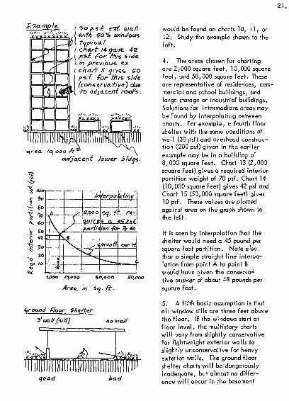
4. The areas chosen for charting
are 2,000 square feet, 10,000 square
feet, and 50,000 square feet. These
are representative of residences, com-
mercial and school buildings, and
large storage or industrial buildings.
Solutions for intermediate areas maybe found by interpolating between
charts. For example, a fourth floor
shelter with the same conditions of
wall (30 psf) and overhead construc-
tion (200 psf) given in the earlier
example may be in a building of
8,000 square feet. Chart 13 (2,000
square feet) gives a required interior
partition weight of 70 psf. Chart 14
(10,000 square feet) gives 42 psf and
Chart 15 (50,000 square feet) gives
10 psf. These values are plotted
against area on the graph shown to
the left.
It is seen by interpolation that the
shelter would need a 45 pound per
square foot partition. Note also
that a simple straight line interpo-
lation from point A to point B
would have given the conserva-
tive answer of about 48 pounds per
square foot.
5. A fifth basic assumption is that
all window sills are three feet above
the floor. If the windows start at
floor level, the multistory charts
will vary from slightly conservative
for lightweight exterior walls to
slightly unconservative for heavyexterior walls. The ground floor
shelter charts will be dangerously
inadequate, but almost no differ-
ence will occur in the basement

shelter charts. Do not rely on the
charts if the design calls for a
ground floor shelter and a sill height
of less than three feet in the exte-
rior walls. Use the charts freely for
all other conditions.
Note that the windows, considered
in the basement charts, occur in the
walls of the floor above. As long as
the outside ground level is at or
above the level of the basement ceil-
ing, windows (window wells) into the
basement will not have too great a
detrimental effect on the level of
radiation protection. They should
not, however, occupy more than,
say, 10 to 20 per cent of the build-
ing perimeter. The charts do not
cover window wells.
6. The charts are designed to givea protection factor of at least 40 in
all parts of the shelter.
7. The story height was arbitrarilyset at 12 feet to generate the data
for the charts. This is reasonable,as radiation level is not greatly
dependent on minor variations in
story height. Note that the aver-
age height to sloping roofs on resi-
dences is similar to the floor-to-
floor height used on most multistory
buildings.
8 . A final assumption, of concernto the architect, is that the building
geometry is simple. The shelter"Js~a simple rectangle within a rectan-
gular building.~
Radiationwise, an L-shaped build-
ing will provide the same protectionas a rectangular building, if the
length of the rectangular building
not too ba.cf , but chart* don't
cove/- thi* condition.
&namedh e i v h t

23.
t
uivct/snTbmlc/intn (
i
t-
4 Jo I rati
&ui/c/ifiy
t/se an area of 5o'x /oo' or fooofo
ne-as cfastynmy an /S9/a/c//fi or 5~ooo &, ft. f/oor-
/*n>fe.c.Tfon from Koo/ fcac/ia. f//on
/nut* vmuutaniusifmimfTmnntittja
tI e I
(il)tii I|MI| 1 1 In i in i null in i nil ii MI |i
5"~ 3. /".sfmt'nimom
a.
ofCarrier*
tola./ Me
is equal to the sum of lengths of the
two legs of the L-shaped building.
It is difficult to give general rules
for the planning of shelters in build-
ings of complex layout. A reason-
able approach, however, is to
design any portion or leg of a build-
ing as if its length were twice its
width (a 2 to 1 ratio), without regard
to the actual length of the building.
This of course is merely a matter of
judgment, but it allows the architect
to select a reasonable (and normally
conservative) area with which to
enter the charts.
THE PRINCIPLES OF SHELTER DESIGN
The purpose of fallout shelter is to enable the
largest possible number of people to survive
the effects of fallout radiation in the event
of a nuclear attack. Hence considerations
such as supply, communications, health, and
management must enter the design problem to
be considered by the architect. However,the single consideration of radiation shielding
must be fully exploited before these others
have meaning.
A radiation shield, like the structural system
of a building, must be basically sound before
attention is turned to its details. The crea-
tive architect should visualize the radiation
condition in terms of the blankets of tiny,
piercing lights at night, lighting up a hazy
sky.
Protection from the blanket of fallout on the
roof can only be obtained by a heavy over-
head barrier or a series of lighter floors and
roofs .*
Dependence should not be placed on washdown and other fallout removal methods.
These methods should be reserved for the post-attack recovery period, after the
shelterees have survived the early effects.

The overhead weight must be at least 90
pounds per square foot, and that only if no
radiation is received from the ground. If
ground radiation is received, the overhead
barrier must be proportionately heavier to
maintain the level of protection required.
Protection from the blanket of fallout on the
ground must be obtained by: (1) walls, either
a single envelope or a series of envelopes,
(2) sinking the building into the ground to
"duck under" the blanket, or (3) ground
sculpture or adjacent construction in combin-
ation with one or more of the above. It is
imperative that a sound, basic system of
shielding against ground radiation be chosen
during the preliminary stage.
To illustrate several means of attaining pro-tection as listed above, three example floor
plans were chosen from the National School
Fallout Shelter Design Competition, 1963,
conducted by the American Institute of Archi-
tects for the Office of Civil Defense.* The
designers of the examples are credited below
each plan.
rr
See item 1 in the bibliography for complete details. Copies were distributed to
all members of the AIA in 1963. Anyone wishing a copy may obtain it by writingto the Office of Civil Defense, Pentagon Building, Washington, D.C. 30210.
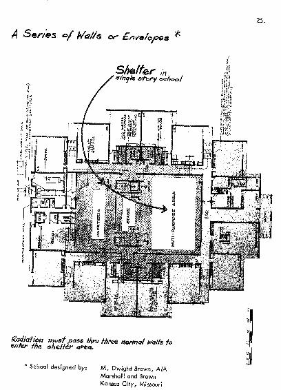
A Series c>
25.
Shelter ;nsfory school
she/f&rthru tfaee /tor/nd w/fe fo
*School designed by: M. Dwight Brown, AIA
Marshal! and Brown
Kansas City, Missouri

26
A ser/es of well-placedintermittant uiaffe *
Core Shelter.2 c0-0

O'8; O
<s>HO

R^ac/iaffon protect/on ob-fainsd byground sculpture in comb/natton

DETAILS
29,
Details often exhibit the real ingenuity of
the architect. For example, Ellery C.
Green, AIA, of Tuscon, Arizona elimin-
ated the "patio" direct radiation from the
shelter area in his prize winning entry in
the American Institute of Architects'
National School Fallout Shelter Design
Competition by providing a simple curb.
The partial perspective shown on the pre-
vious page gives the general character of
the building. The section shown below
shows the patio, the curb and the fact
that the curb requires the direct radiation
line'of
from the patio to pass over the heads of
the shelter occupants.
The radiation reaching the occupants froi
the patio enters after scattering from the
exterior walls or the lip of the curb. Th
scattering causes the radiation to lose a
considerable amount of energy and hence
allows the architect to use lighter sheltei
walls. The planning charts will give
approximations for the required weights c
the interior partitions if the curb is consi
ered to be an exterior wall and a unit
weight is arbitrarily assigned to it.
ofsight c/ears f/ie )j-Mj.
occupqnrs
foflovf

A second example of good detailing is the
choice of exterior walls shown below. Mr.
Francis Telesca, AIA, of Miami/ Florida,
utilized them in his prize-winning presenta-
tion in the AIA competition just cited. The
distribution of wall mass is proportioned to
the intensity of radiation. The most intense
radiation enters through the lower parts of
the wall as ground-direct radiation. The
upper portions predominantly shield against
the less intense scattered radiation.
lighting
Section Intermediate Classroom
ex.i&rlor double - waff planter she/far space.
Section Primary Classroom
light , <*iry s&elfer exterior area
Designed by Francis E. Telesca, A. I.A., Greenleaf/Telesca, Miami,Florida .

DEFICIENCIES IN DESIGN
rr-ont
On/q one liyht barrie
over exposed a.r&a c/bec/oor arrange WCfit.
corr dor
Probably the most common mistake made byshelter planners is leaving holes or leaks in
the protective envelope encompassing the
shelter. Doorways often will not be offset so
that radiation from the fallout lying on the
ground has relatively unrestricted access. In
the simplified floor plan shown to the left the
exterior door lines up on an interior ddor such
that only a light partition impedes radiation
access. This creates a "hot spot" located in
a highly trafficked area, thus increasing the
general level of radiation exposure to the
group of occupants.
Note that in all other directions from the front
of the building the radiation must pass throughat least two walls, the sum of the weights of
which is adequate.
Another common mistake is failure to consider
the radiation problem in three dimensions.
The two-story wing of an actual school is
shown to the left. The section is taken longi-
tudinally through the corridor-shelter. The
double overhead barrier provides adequateroof protection. The exterior walls have been
designed to minimize ground contribution. The
two-story section has been lowered, with
respect to the ground outside, to allow the
shelter occupants to begin to "duck under"
the direct ground radiation.
The mistake occurs in not recognizing that the
shelter occupants can see the ceiling of the
adjacent one-story portion of the school, and
hence be "seen" in return by the radiation
from fallout lying on this roof. Since the cor-
ridor lines up on this roof it constitutes a
major breach in the protective envelope.

32.
EXAMPLES OF DESIGN USING THE
CHARTS
To present design examples illustrating the use
of the charts, the writer has chosen two addi-
tional designs submitted by practicing archi- .
tects for national AIA competition. With the
architects permission, revisions have been
made where considered advantageous to
improve the clarity of the point being dis-
cussed.
Case 1, A One-Story School
The building, the floor plan of which is shown
to the right, is the preliminary design of a sin-
gle story school. The middle portion of 80'
x 180' is to be shelter. It is assumed that no
material weights have been chosen -except
those shown. The remaining weights of the
walls and partitions, and the roof weight are
desired.
The roof weight is logically the one to choose
first. It should be as light as practical to be
low cost and devoid of supporting columns in
the multi-purpose area if possible. The build-
ing has an area of 140' x 180' or approxi-
mately 25,000 square feet. The shelter is on
the ground floor.
Arbitrarily assuming that walls A and C are
typical all around the building, and that wall
C tentatively weighs 100 pounds per square
foot, reference to Chart 5 (10,000 square
feet) indicates that the roof weight should be
about 105 psf. Chart 6 (50,000 square feet)
indicates a value less than 100 psf. Onehundred pounds per square foot is the lightestroof that can be used to provide PF 40.
At this time, it should be noted that lines
which intersect as these did on Chart 6 belowand to the right of the 100 psf overhead
weight curve, indicate an impossible condi-
tion. This chart says that the overhead
Assumptionsae\. roof Weight ")

windows over 3in 4" focc brck 4 4"concne
Joseph Baker, Architect, A1A
Joseph Baker and Associates
Newark, Ohio

34.
weight cannot be less than 100 psf to give a
PF 40 in a 50,000 square foot building. The
roof contribution is too great no matter what
the wall contribution may be. Therefore 100
psf is the minimum allowable roof weight for
a 50,000 square foot building.
For a 25,000 square foot shelter use 100 psf
(equivalent to an 8" concrete slab).
Assuming that the school board is willing to
accept the 100 psf roof, let us continue to
determine the remaining weights.
With a 100 psf roof, a wall A weighing 70 psf
up to the 3-foot sill, and all glass above,Chart 6 indicates that wall C should be 86 psf,
Chart 5 indicates that wall C should weigh1 10 psf. Simple interpolation as shown to the
right indicates that the tentative choice of
100 pounds for the unit weight of wall C is a
good one. Use 100 pounds per square foot
for wall C.
The condition of wall D is such that no inte-
rior partitions occur. Chart 5, for no win-
dows and a 100 psf roof, gives a wall weightof 180 psf. Chart 6 gives 155 psf. Interpo-
lation gives 170 psf as the required value.
Wall E, assuming arbitrary average of 1 1/2
partitions (45 psf) yields 125 psf (Chart 5),
and 100 psf (Chart 6), which interpolate to a
115 psf required weight.
The single story school shelter with these
weights will have a protection factor of at
least 40. The school will sa.tisfy the mini-
mum Office of Civil Defense requirements.*
With a little practice and familiarity with
shielding design, the interpolation may be
done by simple guess work. As most designs
(2.5,000)
A reA.
50,000
(Jo. /I
|60 L
Area.
See Appendix.

will be approximations of the design assump-tions used in the development of the charts,
the answers obtained from the charts cannot
be assumed to be overly precise. The charts
were designed to get the shelter planner into
the ball park quickly.
It will become apparent, after using the
charts, that a ground floor shelter is the most
difficult type to design using normal construc-
tion. Both the walls and the roof will be
heavier than required by normal architectural
considerations unless creativity is rampant.
Case 2, A Multistory Building*
Assume the architect is checking the neces-
sity of utilizing the inner and outer folding
radiation barriers on the sixth floor, as shown
typical floor shon/n in
perspective below
operableshutters
(barrier
Designed by Charles William Brubaker, Edward C. Colin, Hem C. Gupta,JohnF. Janiga, and James All yn Steward, for the A. I.A. National School
Fallout Shelter Design Competition 1963.
J6.
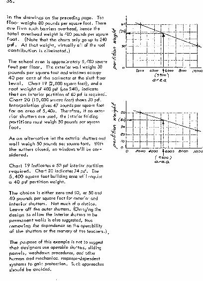
In the drawings on the preceding page. The
floor weighs 80 pounds per square foot. There
are five such barriers overhead, hence the
total overhead weight is 400 pounds per squarefoot. (Note that the charts only go up to 240
psf . At that weight, virtually all of the roof
contribution is eliminated.)
The school area is approximately 5,400 square
feet per floor. The exterior wall weighs 30
pounds per square foot and windows occupy40 per cent of the perimeter at the sixth floor
level. Chart 19 (2,000 square feet), and a
roof weight of 400 psf (use 240), indicate
that an interior partition of 60 psf is required.
Chart 20 (10,000 sauare feet) shows 30 psf.
Interpolation gives 47 pounds per square foot
for an area of 5,400. Therefore, if no exte-
rior shutters are used, the interior folding
partitions must weigh 50 pounds per square
foot.
As an alternative let the exterior shutters and
wall weigh 50 pounds per square foot. With
the sutters closed, no windows will be con-
sidered.
Chart 19 indicates a 50 psf interior partition
required. Chart 20 indicates 24 psf. The
5,400 square foot building area will require
a 40 psf partition weight.
The choice is either zero and 50, or 50 and
40 pounds per square foot for exterior and
Interior shutters. Not much of a choice.
Leave off the outer shutters. (Changing the
design to allow the interior shutters to be
permanent walls is also suggested, thus
removing the dependence on the operability
of the shutters or the memory of the teachers. ) t
The purpose of this example is not to suggest
that designers use operable shutters, sliding
panels, washdown procedures, and other
human and mechanical response-dependent
systems to gain protection. Such approaches
should be avoided.
/ 0,000

Alternate 1.
Alternate.
The purpose is rather to illustrate the uses to
which the, charts may be put and to discuss
the characteristics of radiation which influ-
ence design. Note that the first solution
(Alternate 1) requires less total mass than the
second by almost a factor of two.
Why is this? The answer is that the most
intense radiation, that coming from the first
hundred yards around the building, is below
the line of sight of the shelter occupant.Since it travels in relatively straight lines,
it must pass through a floor barrier to get into
the shelter. If a light wall, say 50 psf or
less, is placed on the outside of the building
this radiation can "see" it and hence scatter
from it.
In Alternate 1, skyshine is coming through the
windows, requiring a 50 pound interior parti-
tion. In Alternate 2, the skyshine has been
virtually eliminated by the outer shutters, but
radiation now scattering from these shutters
and into the shelter has replaced it. It has
been replaced to the extent that now a 40
pound per square foot interior partition is
required.
The phenomenon occurs, as was previously
discussed, in the basement shelters. A base-
ment shelter offers better protection when the
walls on the floor above have negligible
weight (say, glass), than when a lightweight
wall (10 to 50 psf) is used. Recall from the
discussion on page 15 that radiation had to
scatter to enter the shelter.
Use a heavy wall or a wall of negligible
weight. Avoid the use of walls between the
10 and 50 pound per square foot weights to
minimize the scattering-in of radiation.

38.
SHELTER PLANNING DISCUSSION ANDSUMMARY
The Analogy
The greatest freedom for design can be had if
the architect fully understands the analogy of
the clouded-glass structure. The sheets of
tiny flashing lights represent the fields of fall-
out. All construction is translucent to this
light in a manner proportional to the mass and
density of the materials of construction.
Light will reflect from a surface. A polished
sheet of metal or a mirror will reflect light.
Gamma radiation, however, does not see a
wall surface. A wall, to radiation photons,
is like a galaxy of stars into which the pho-tons are traveling.
Collision between gamma photons and atomic
particles of matter in a wall is random. Scat-
tering or ricocheting occurs in random direc-
tions and at differing depths into the galaxy.
Thus, a stream of radiation striking a wall
will not reflect with an angle of reflection
equal to its angle of incidence. Radiation
scatter will occur somewhat like a stream
of water trained upon a heavy metal sieve.
The readers' concept of the clouded-glass
structure should include this understanding.
It must not be concluded from the analogy that
the darker or more gloomy the space becomes
(with respect to natural light), the better the
radiation shielding. Neither must it be
assumed that all spaces in a building which
offer good shelter must be dark and gloomy.Most decidedly not! The space, unless it is
bright and cheerful, will not be fully usable
during peace time.
A space is dark if sunlight or artificial illu-
mination does not reach it. During a disaster
electric power may not be available, so the
previous sentence may be shortened to: "A
space h dark if sunlight does not reach it."
Po/nf 5u i"c.
Fallout
IN 1 1 u i in i III Hi I M i fi ni 1
1 1m 1 1 1 In/mi i iffnil I J I fin rrnT
Field Source.
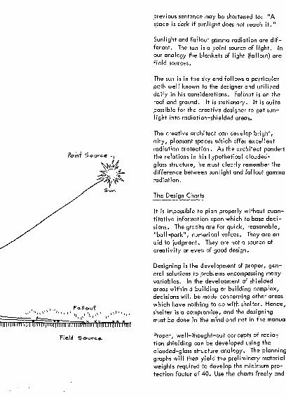
Sunlight and fallout gamma radiation are dif-
ferent. The sun is a point source of light. In
our analogy the blankets of light (fallout) are
field sources.
The sun is in the sky and follows a particular
path well known to the designer and utilized
daily in his considerations. Fallout is on the
roof and ground. It is stationary. It is quite
possible for the creative designer to get sun-
light into radiation-shielded areas.
The creative architect can develop bright,
airy, pleasant spaces which offer excellent
radiation protection. As the architect pondersthe relations in his hypothetical clouded-
glass structure, he must clearly remember the
difference between sunlight and fallout gammaradiation.
The Design Charts
It is impossible to plan properly without quan-titative information upon which to base deci-
sions. The graphs are for quick, reasonable,
"ball-park", numerical values. They are an
aid to judgment. They are not a source of
creativity or even of good design.
Designing is the development of proper, gen-eral solutions to problems encompassing manyvariables. In the development of shielded
areas within a building or building complex,decisions will be made concerning other areas
which have nothing to do with shelter. Hence,
shelter is a compromise, and fhe designing
must be done in the mind and not in the manua
Proper, well-thought-out concepts of radio-?
tion shielding can be developed using the
clouded-glass structure analogy. The planning
graphs will then yield the preliminary material
weights required to develop the minimum pro-
tection factor of 40. Use the charts freely and

40.
without concern. Shelter analysts should
verify and refine the weights. The varia-
tions found will be more often conceptual
than numerical .
Summary
Fallout resembles sand, dust, or ash. The
radioactive bomb fragments attached to
it emit radiation which may damage or
destroy living tissue. In a large attack
about 75 per cent of the land area of the
United States could be affected by fallout.
Since less than 10 per cent may be
affected by blast and heat, radiation pro-
tection is worth considering. It is the
basis for the civil defense shelter system.
Radiation protection is relatively simple
to design. Basements and interior por-
tions of the upper floors of multistory
buildings can easily offer adequate pro-
tection using normal materials of con-
struction. Ground floor shelters are
usually more difficult, heavier, and more
expensive. However, creative solutions
have been developed by architects which
satisfy all requirements.
The two major sources of radiation are the
fallout fields on the roof and the ground.
Radiation enters a shelter by direct line of
sight, by scattering from atoms of the
building materials and by scattering from
atoms in the atmosphere. These three types
are called direct radiation, wall -scattered
radiation, and skyshine. Skyshine is nor-
mally of minor importance. Hence, clere-
story lighting is permissible in fallout
shelters.
The three basic types of shelters have been
discussed. The below ground, at ground
level, and aboveground shelters, have
intense ground radiation, leaving only
the roof radiation and radiation scatter-
ing down from the walls above to be con-
sidered. The ground floor shelter or
shelter at ground level in a single story
building is fully exposed to ground radia-
tion as well as roof radiation. Creati-
vity is required to bring down the cost.
The shelter in the multistory building has
the advantage of being moved up and
away from the ground radiation and is
several floors below the roof. Hence, as
barriers are naturally located between
the fallout and the shelter occupant, nor-
mal construction and normal costs are
usually encountered. Adequate radiation
protection is inherent in normal design.
Of course not all multistory buildings pro-
vide adequate protection, but normally
only minor design changes are encoun-
tered. Look for shelter first in below-
ground areas, then in multistory areas,
then gird yourself with ingenuity and
design it on the ground floor.
THE DESIGN CHARTS
The following charts are designed to give
approximate numerical values for material
weights of exterior walls, interior parti-
tions, and overhead construction for sim~
pie shelters. These charts are developedto provide those combinations which will
yiefd a minimum protection factor of
forty (40) within the shelter. It is
expectecr that designs developed through
the use of these charts will be verified by
qualified shelter analysts before being
finalized.

BASEM
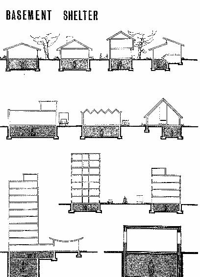
BASEMENT SHELTER
BUILDING AREA 2,000 SQ. FT.
ICO
h-
UJCO
<
oQz
os!
a:
LUQ.
IUJ
oz
u
LU
to<CQ
120-*Total Overhead Weight (psf) Exclusive A DT

100BUILDING AREA 10,000 SQ. FT.
TMAPT

100-BUILDINS AREA 50,000 SQ. FT.
yj
UJI
ZUJ
5UJ
120
Total Overhead Weight (psf) Exclusive TMART


GROUND F
GROUND FLOOR SHELTER
DESIGN SECTION
BUILDING AREA 2,000 SQ. FT.

BUILDING AREA 10,000 SQ. FT.
oQZ
u_
Oo
DCLUH-m
yj s
O K-
0)
zo
oUJH-
Z
A mr

BUILDING AREA 50,000 SQ. FT.
LLJ
.|-
LLJ
I
U,
8LL
OZO
CO
OaZ
OO
LU
UJa.
OUJ
ZO
oUJt
Z


ABOVEGROUND SHUT I

ABOVEGROUND SHELTER
SECQNDF RSHELTER
rub

100-
BUILDING AREA 2,000 SQ. FT.
oo
ouLJJ
to
CO
oZ
oo
a;UJ
LU0.
O
Zo
oUJH-
z

BUILDING AREA 10,000 SQ. FT,
LU|
LUI
oo
QZOuLUto
to
oQZ
oo
UJQ-
xO
Zo
OC
ADT

100BUILDING AREA 50,000 SQ. FT.
gUJI
z
140
160-
180-
200-
220-
240-

ABOVEGROUND SHELTER
THIRD FL SHELTER
BUILDING AREA 2,000 SQ. FT.
Ito
QL
OO
Q
co
Oz
LU
OO
LUQ_
XO
ZO
gLUH-
z

BUILDING AREA 10,000 SQ. FT.
100-
ULJ
I
OOLL
Q
to
OQz
OO
i
UJ
ex.
s
XOUJ
ZO
goi
rMAPT II

BUILDING AREA 50,000 SQ. FT.
UJ
XtO
oo
Q
I
to
OQ
u_
O
UJh-LU
LUQ_
OL
OLU
1.
O
C
OLUI
z

62.
ABOVEGROUND SHELTER
FOURTfT^FL SHELTER

BUILDING AREA 2,000 SQ. FT.
LLJ
oo
OUL
CO
O
Oo
LLJ
h-LLJ
CXLLLJ
CL
o
zo
oLLJ
I
Z
240

62.
ABOVEGROUND SHELTER
SHELTER

100
BUILDING AREA 2,000 SQ. FT.
A OT

FOURT
100
BUILDING AREA 2,000 SQ. FT.
/-LJADT

EJJ
i
ULS
ILUQ_
BUILDING AREA 10,000 SQ. FT.
10
OO
OLL
XOLLJ
zO
20-
40-
60-
80-
100-
120
OS 180-H-
z-200
220

100-
BUILDING AREA 50,000 SQ. FT.
oo
ID
oUL
LO
oQz
_
oo
LJU
XO
ZO
Qi
oLUJ
Z
A QT IF

66.
ABOVEGROUND SHELTER
FIFTl~~FJJ SHELTER
BUILDING AREA 2,000 SQ. FT,
LU|-
LU
Ico
OO
LL
to
oQz
LJL.
O
ct;LUQ_
XOLU
Zo
qLUI
z

BUILDING AREA 10,000 SQ. FT.
UJ
oOUL
I
sPs-
CO
oQz
oo
1
UJ
UJa.
OUJ
Zo
gUJh-
Z
100-
240

BUILDING AREA 50,000 SQ. FT.
UJ
Zto
QOo
220
240-

70.
ABOVE6ROUND SHELTER
SIXTH SHELTER

Q_
OUJI
Z180
200
220-
240-

BUILDING AREA 10,000 SQ. FT,
oQZ
u_
Oo
atui
UJIto
bE.
u.
I
UJa
UJ
Zo
Ou
a:
O

ULJ
I
8
IX
oQZ
UL.
Oo
LUQ.
a.
XOLU
Zo
on
qULJ
I
Z
THAPT

APPENDIX


DEPARTMENT OF THE ARMYOFFICE OF THE SECRETARY OF THE ARMY
WASHINGTON, D.C. 2031O
[Technical Memorandum 6l-3 (Revised)- ,. March 1965*
Offfe* of Civil Dcfenta^ '
TECHNICAL REQUIREMENTS FOR FALLOUT SHELTERS
I. General
The purpose of this technical memorandum is to establish officialstandards for fallout shelters.
II. Terminology
A. Protection Factor. A factor used to express the relationbetween the amount of fallout gamma radiation that vould "be receivedby an unprotected person and the amount that would be received by onein a shelter. For example, an occupant of a shelter with a EF of k-0
would be exposed to a dose rate 1/40 (or 2^) of the rate to which hewould be exposed if his location were unprotected.
B. Fallout Shelter. A structure, room or space that protectsits occupants from fallout gamma radiation, with a protection factorof at least MD.
HI- Radiation Shielding
A. Computation of protection factors shall be made by methods
acceptable to the Office of Civil Defense.
B. In the calculation of the protection factor, the radiationdose contribution to the shelter occupants coming from the entrance-frays ,
ventilation ducts or other openings in the shelter's barriers shall beconsidered .
IV. Shielding Requirements
Detailed DoD studies of the lifesaving potential of fallout shelters
indicate that for the current time-frame and for the foreseeable future,shelters with a protection factor of kO could save over 9$ of those
persons who would otherwise die if unprotected against potential lethalradiation levels. Therefore, design and construction objectives are:
A. Shelters for the General Population. In modifications to
existing buildings and in new construction, protection factors and
shelter areas should be maximized to the extent possible, at nominal
or no cost, using slanting techniques (See TM 6^-2). Although minimum
protection for a shelter area should be at least EF 40, the objective is
to obtain the best protection factor possible. Computations indicate that
decreasing returns in added lives saved per added dollar invested are
obtained as HP's are increased significantly above 40. On a nationwide
basis, therefore, it would provide better life-saving potential per dollar,for the same dollar expenditure, to obtain more shelter space of lower EFthan only a few shelter spaces vith very kigh EF.
^Supersedes TM 6l-3, August

78
B. Shelters for Emergency Operational Personnel. As it is
anticipated that personnel with emergency functions may have to exposethemselves to dangerous radiation levels during the performance of their
duties, it is desirable to obtain the best possible protection factors
for emergency operating centers or shelters housing emergency operational
personnel, with an acceptable minimum objective of at least 100 PF.
C. Recognizing that in many design and construction projects it maybe physically difficult or expensive to attain these minimum shielding
objectives, it is still a worthwhile objective to increase protectionfactor-j to any level. Under many potential levels of radiation exposure,even these lower protection factors will save lives or minimize illness.
V. Space and Ventilation Requirements
A. Ten square feet of shelter floor area per person shall be provided.
Bo At least 65 cubic feet of space per person shall be provided.
C If the shelter capacity is 'based on minimum space requirements,then at least 3 cubic feet of fresh air per minute per person are required.
D. Shelter capacity or occupancy time may be limited by the volumeof the room and not by its area. This is particularly true if mechanicalventilation is inadequate. When ventilation is limited, the followingtable can be used for determining the relation of space requirements to
ventilation:
Time for one complete Volume of Space requiredair change (minutes)* per person (Cu. Ft.)
1,000 or more ______ 500600 - ______ 450lj-00 - lj-00
200 ------------------ 300100 20060 __________________ 15035 - 10022 65
* Computed as a ratio: Net volume of space ( cu . ft . )
Fresh air supply (cfm)
E. No filters are required on mechanical ventilation systems otherthan those necessary for the normal daily use of the space.
F. In general _,incremental costs of fixed ventilation equipment
to meet shelter requirements shall not exceed $2.^0 per shelter space,the estimated cost of ventilating the shelter with packaged ventilationequipment approved by the Office of Civil Defense.

VI. Construetion Requirements
A. In general, conventional methods of design and constructionfor concrete, wood, steel } brick, structural tile and other products
will "be followed. Allowable stresses and/or load factors as defined
in the applicable codes shall be used.
B. The structure shall be designed for a useful life of at
least 10 years .
C. At least one unit of access and egress width should be
provided for every 200 shelter occupants (a unit width is 22inches,
the space required for free travel of one aisle of persons). In no
case shall a single passage width be less than 2k inches; nor shall
there be less than two widely separated means of egress from each
building. -Emergency-type hatchways may be used as a means of egress,
They shall be designed so that any normal-size adult can readilyenter or leave the main shelter chamber.
D. In areas subject to high-ground water conditions, provisions
shall be made to prevent flotation of underground shelters.
E. Provisions shall be made to insure the shelter interior -will
remain reasonably dry.
F. To the extent practicable, hazardous utility lines such as
steam, gas, etc., should not be located in or near the shelter area
unless provision is made to control such hazards before the shelter
is occupied.
G-. All shelters shall be constructed to minimize the dangerof fire from both external and internal sources.
VII. Services
A. Provisions shall be made for the storage of basic shelter
supplies by allotting 1^- cubic feet per person. This volume may "be
reduced to 0.6 cubic feet per person if the standard OCD IT"! gallon
water drums are not utilized. The live load attributable to placingthese supplies should be considered. Fallout shelters with a capacity
of 50 or more persons, which have been made available to the publicshould be stocked with:
1. Water - to provide each person vith a minimum of
3-g- gallons of water.
2. Food - special crackers, biscuits, or wafers, etc.,to provide 10,000 calories per person, deducting
comparable food already available in the building.
3. Medical care kits.

80
Ij-. Sanitation kits -which include toilet tissue, sanitary
napkins , toilet .seat and commode chemicals. Empty water
containers convert to commodes.
5. Radiation detection instruments.
B * Water Supply. An adequate supply of water from a suitable well,water trapped in the piping of the facility, or water storage tanks should
be substituted, wherever feasible, for storage of drinking water in the
standard OCD ITi" gallon water drums.
c> Sanitation. Toilets may be provided on the basis of one per50 occupants. In lieu of VII A h above, other austere provisions, basedon economic considerations may be made for the disposal of garbage, trash,and human waste. Fifty percent of the toilets may be outside the shelter
area, in other parts of the building, provided they are readily accessiblewithout hazardous escposure to fallout gamma radiation.
D. Electrical power. It is assumed that normal electrical power willbe available, therefore emergency generators are not required. No speciallighting levels are required in fallout shelters. The following levels aredeemed adequate for emergency occupancies:
1. Sleeping areas - 2-foot candles at floor level.
2. Activity areas - 5 -foot candles at floor level.
3- Administrative and medical areas - 20-foot candlesat desk level.

BIBLIOGRAPHY


BIBLIOGRAPHY
1. TR-19, "AWARDS, AIA National School Fallout Shelter Design Competition;11
Office of Civil Defense, Department of Defense, February 1963.
2. TR-21, "Industrial Architecture, Fallout Shelters," Office of Civil Defense,
Department of Defense, June 1963.
3. TR-27, "New Buildings With Fallout Protection,"Office of Civil Defense,
Department of Defense, January 1965.
4. TR-28, "AWARDS, AIA National Community Fallout Shelter Design Competition,"Office of Civil Defense, Department of Defense, November 1964.
5. TR-32, "City Halls with Emergency Operating Centers," Office of Civil Defense,
Department of Defense, Washington, D.C.
6. TM-64-1, "Protection Factor Estimator," Office of Civil Defense, Department of
Defense, May 1964.
7. "Shelter Design and Analysis, Vol. 1, Fallout Protection," Office of Civil
Defense, Department of Defense, May 1964.
8. "Shelter Design and Analysis, Vol. 2, Equivalent Building Method," Office of
Civil Defense, Department of Defense, October 1964.
9. "Prototype Hospital- Fallout Protected," Architectural Record, May 1961 (pp 155).
10. DSS 55-5, "Aboveground Clay Brick Masonry Core Fallout Shelter," Office of
Civil Defense, Department of Defense, March 1964.
11. PG-80-1, "Incorporation of Shelter into Schools," (Interim Edition), Office of
Civil Defense, Department of Defense, November 1962.
12. PG-80-4, "Incorporation of Shelter into Apartments and Office Buildings" (Interim
Edition), Office of Civil Defense, Department of Defense, November 1962.
13. Glasstone, S. (Edit.): The Effects of Nuclear Weapons, Rev. Edit., February 1964,
United States Atomic Energy Commission, Washington, D.C.
DISTRIBUTION;
OCD Regions, Staff College Deans of Engineering