Embed Size (px)
Citation preview
Designing High Performance Enterprise Wi-Fi Networks
Rohan Murty†, Jitendra Padhye‡, Ranveer Chandra‡, Alec Wolman‡, Brian Zill‡†Harvard University, ‡Microsoft Research
Use of mobile computing devices such as laptops, PDAs,and Wi-Fi enabled phones is increasing in the workplace. Asthe usage of corporate 802.11 wireless networks (WLANs)grows, network performance is becoming a significant concern.We have built DenseAP, a novel system for improving the per-formance of enterprise WLANs using a dense deployment ofaccess points (APs). In sharp contrast with wired networks, onecannot increase the capacity of a WLAN by simply deployingmore equipment (APs). To increase capacity, the APs must beassigned appropriate channels and the clients must make intelli-gent decisions about which AP to associate with. Furthermore,the decisions about channel assignment, and associations mustbe based on a global view of the entire WLAN, rather than thelocal viewpoint of an individual client or AP. Given the diver-sity of Wi-Fi devices in use today, another constraint on the de-sign of DenseAP is that it must not require any modification toWi-Fi clients. In this paper, we show how the DenseAP systemaddresses these challenges, and provides significant improve-ments in performance over existing WLANs.
1 Introduction
In a typical office environment, the wired network isgenerally well-engineered and over-provisioned [12]. Incontrast, deploying 802.11 wireless networks (WLANs)in enterprise environments remains a challenging andpoorly understood problem. WLAN installers typicallyfocus on ensuring coverage from all locations in theworkplace, rather than the more difficult to measureproperties such as capacity or quality of service. Thus,WLAN users commonly experience significant perfor-mance and reliability problems.
The usage model for enterprise WLANs is currentlyundergoing a significant transformation as the “cultureof mobility” takes root. Many employees now prefer touse their laptops as their primary computing platform,both in conference rooms and offices [18]. A plethoraof handheld Wi-Fi enabled devices, such as PDAs, cellphones, VoIP-over-Wi-Fi phones, and personal multime-
dia devices are becoming increasingly popular. In addi-tion to the scalability challenges that arise with increasedWLAN usage, the applications for many of these newmobile devices require better QoS and mobility support.
The need to improve enterprise WLAN performancehas been recognized by both the research commu-nity [20, 19, 7, 10, 24] as well as industry [3, 5, 2, 4, 1].Upgrades at the PHY layer, such as the transition from802.11g to 802.11n, are important steps along the path toincreasing WLAN capacity, but they are not enough. De-ploying more APs has the potential to improve WLANcapacity, but one must also address issues such as chan-nel assignment, power management, and managing asso-ciation decisions.
In this paper, we present a new software architec-ture called DenseAP, that supports a dense deploymentof APs to significantly improve the performance of cor-porate WLANs. A key emphasis in our design of theDenseAP system is on practical deployability. Becauseof the incredibly wide diversity of existing Wi-Fi de-vices, DenseAP must provide significant performancebenefits without requiring any modifications to existingWi-Fi clients. Furthermore, we do not consider anychanges that require hardware modifications or changesto the 802.11 standard.
The DenseAP architecture and design challenge twofundamental characteristics of most current enterpriseWLAN deployments. First, existing WLANs are de-signed with the assumption that there are far fewer APsthan clients active in the network. In the DenseAP archi-tecture however, the APs are deployed densely – in thecommon case there may be an AP in every office. Sec-ond, in conventional WLANs clients decide which APto associate with, whereas the DenseAP system uses acentralized association control.
The scarcity of APs in conventional enterpriseWLANs limits their performance in a variety of ways.For example, with a large number of non-overlappingchannels (e.g. 12 in 802.11a) but only a few APs, the
1
NSDI ’08: 5th USENIX Symposium on Networked Systems Design and ImplementationUSENIX Association 73

WLAN is unable to fully utilize the available spectrumat each location. Because radio signals fade rapidly inindoor environments, adding extra radios to existing APsis not as effective as deploying a larger number of APsin different locations. If APs are densely deployed, eachclient can associate with a nearby AP, and will see bet-ter performance. A dense deployment also reduces theimpact of the “rate anomaly” problem [13] that hurts theperformance of conventional WLANs.
With a dense deployment of APs, clients have manypossible APs to choose from, and therefore access pointselection policy is critical to achieving good perfor-mance. In conventional WLANs, clients select whichAP to associate with using only locally available infor-mation. Most clients use signal strength as the dominantfactor in selecting an AP, yet it is well-known that this be-havior can lead to poor performance [14]. For example,when many clients congregate in a conference room, theyall tend to select the same AP even when multiple APsoperating on different channels are available. To improveperformance in this scenario, clients must associate withdifferent APs.
In the DenseAP architecture, a central controller gath-ers information from all APs, and then determines whichAP each client should associate with. Simultaneously,the central controller also decides on the assignmentof channels to APs. Even though Wi-Fi clients imple-ment their own association policies and we do not mod-ify these clients, the DenseAP controller effectively by-passes the client association policy by only exposingto each client the particular AP with which it wantsthe client to associate. Using a similar technique, theDenseAP controller also carries out periodic load balanc-ing by seamlessly moving clients from overloaded APsto nearby APs with significantly less load.
The DenseAP architecture is quite versatile, and ca-pable of improving many aspects of performance of en-terprise WLANs. In this paper, we primarily focus ondescribing how DenseAP significantly improves the ca-pacity of enterprise WLANs. We define capacity sim-ply as the sum total of throughput all active clients inthe network can potentially achieve. We will also brieflydiscuss how the architecture impacts other aspects of per-formance, such as quality of service for delay and jittersensitive applications.
One obvious question that arises when consideringa dense AP deployment is whether the performancegains justify the costs. One approach to reducing equip-ment costs is to leverage existing enterprise desktopsand convert them to APs, similar to our previous workon DAIR [8]. However, the key concern of enterpriseIT departments when deploying any new technology istypically the people costs associated with managing thattechnology. The DenseAP system is designed to require
Figure 1. Overall architecture of the DenseAP system.
very little management overhead: the DenseAP nodesare self-configuring, and the redundancy available fromthe dense deployment means that AP hardware failuresdo not need to be addressed immediately.
This paper makes the following new contributions.First, our system supports a high density of APs withoff-the-shelf, completely unmodified clients. As a result,it provides performance benefits for all clients, includingthe many different types of handheld Wi-Fi devices thathave recently appeared. Second, we demonstrate the per-formance benefits of our system at a significantly higherdensity than previous work. Third, we demonstrate thatintelligent management of the association process is nec-essary even when you have a very high density installa-tion of APs. Forth, we present a novel load estimationtechnique that allows our system to automatically factorin impact of external interference, such as traffic fromnearby networks.
We have deployed the DenseAP system with 24 APsin our offices. The testbed can function in both 802.11aand 802.11g modes. Our experiments show that the sys-tem provides large improvements in performance overthe existing corporate network. In specific cases, the im-provement in throughput can be as large as 1250%. Wepresent a series of experiments that show how various as-pects of our system work together to provide these gains.We also show that our system is capable of handling no-madic and mobile clients.
2 Design Overview
Figure 1 is a high-level illustration of the DenseAP sys-tem. The system consists of several DenseAP nodes(DAPs) which provide wireless service and a DenseAPcontroller (DC) which manages the DAPs.
A DAP is a programmable Wi-Fi AP connected to thewired network. Each DAP periodically sends summariesto the DenseAP controller comprising of a list of associ-ated clients, their traffic pattern summaries, RSSI valuesof a few packet samples from their transmissions, currentchannel conditions, and reports of new clients requestingservice from the network. We classify DAPs into twocategories: we refer to DAPs that do not have any clientsassociated with them as passive; those that have at least
2NSDI ’08: 5th USENIX Symposium on Networked Systems Design and Implementation USENIX Association74
one associated client are called active.The DC manages the DAPs. The periodic reports sent
by the DAPs provide the DC with a global view of thenetwork activity. Using this global view, the DC se-lects the right DAP for a client, allocates channels toDAPs, performs load balancing when needed, handlesclient mobility, and deals with DAP failures.
In the next section, we describe the mechanisms theDC uses to ensure that the client associates with the se-lected DAP. Then, we describe the algorithms involved inselecting the DAP and a channel for the DAP. We discusspower control and related issues in Section 5
3 Association Mechanism
In conventional WLANs, APs advertise their presenceby sending out Beacon frames which include their SSIDand BSSID. Prior to association, clients gather infor-mation about the APs by scanning the channels one byone, and listening for Beacons on each channel. This iscalled “passive scanning”. The clients also perform “ac-tive scanning”, whereby they send out a Probe Requestframes on each channel. These are requests for APs tosend out information about themselves. APs respond toProbe Requests with Probe Response frames, the con-tents of which are similar to Beacon frames. Once theclient gathers information about all APs, it decides whichAP to associate with.
The 802.11 standard allows APs to beacon with theSSID field set to null – this is referred to as a hiddenSSID. A client that wishes to associate with an AP us-ing a hidden SSID must first send out a Probe Requestthat contains the SSID of that network, which will thencause the AP to provide a Probe Response. For any clientthat does not provide the correct SSID, the AP does notrespond.
The DC performs association control by exposingDAPs to clients on a “need to know basis”. This isachieved as follows. First, the passive DAPs (i.e., thosethat do not have clients associated with them) in the net-work do not send out any beacons. The active DAPs dosend out beacons but with a hidden SSID. Second, eachDAP maintains a local access control list (ACL) of clientMAC addresses. On receiving a probe request from aclient, the DAP replies with a probe response messageonly if the client’s MAC address is in its ACL. If a DAPreceives a probe request (it may be a broadcast request)from a client whose MAC address is not in its ACL, itsends a message to the DC informing the controller thata client might be requesting service. The DC determineswhich, if any, DAP should respond to the probe requestand adds the MAC address of the client to the ACL ofthat DAP.
Figure 2. Association in the DenseAP system
By adding the MAC address of a client to only oneDAP’s ACL at a time, the DC ensures that for the SSIDassociated with the DenseAP network, only one DAP isvisible to the client at any given time.
Note that traditional MAC address filtering could nothave achieved this. MAC address filtering only preventsassociation, not probe responses. With traditional MACaddress filtering, a client would discover several DAPs,and it may not even try to associate with the one that theDC has chosen for it.
We will now illustrate how these two techniques areused when a client associates with the system for the firsttime, and handing off a client from one DAP to another.
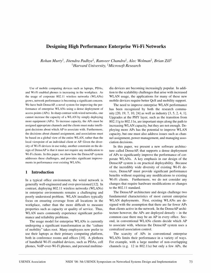
3.1 Associating New ClientsFigure 2 illustrates the association mechanism instru-
mented in DenseAP. (i) A new client C with mac ad-dress C
mac broadcasts probe requests. (ii) DAPs DAP1
and DAP2 receive probe requests and inform the DCof Cmac. (iii) The DC executes the association algo-rithm and determines which AP the client should asso-ciate with. Assuming it picked DAP1, the DC then sendsa message to DAP1 to add Cmac to its access control list(ACLDAP1
). (iv) DAP1, on receiving the next probe re-quest from C, checks to see if Cmac
∈ ACLDAP1. If so,
it responds to C with a probe response thus initiating theassociation process. If DAP1 was not previously bea-coning, it now begins.
The reader may wonder why DAPs beacon at all.One reason is that beacons are essential for allowing theclients to enter power-save mode. In addition, certainpopular drivers automatically disconnect from an AP ifthey do not receive periodic beacons.
We note a few points about this mechanism. First, wehave verified that this mechanism works with the devicedrivers of a variety of popular 802.11 chipsets includ-ing Atheros, Intel Centrino, Realtek, Ralink, and Prism2.Second, if a client fails to associate with the assignedDAP (e.g. due to interference near the client), the DCdetects this since DAPs periodically report back infor-mation about their associated clients. The DC then re-assigns the client to a different DAP. Third, ACL entryfor a client is maintained only as long as the client is as-
3
NSDI ’08: 5th USENIX Symposium on Networked Systems Design and ImplementationUSENIX Association 75
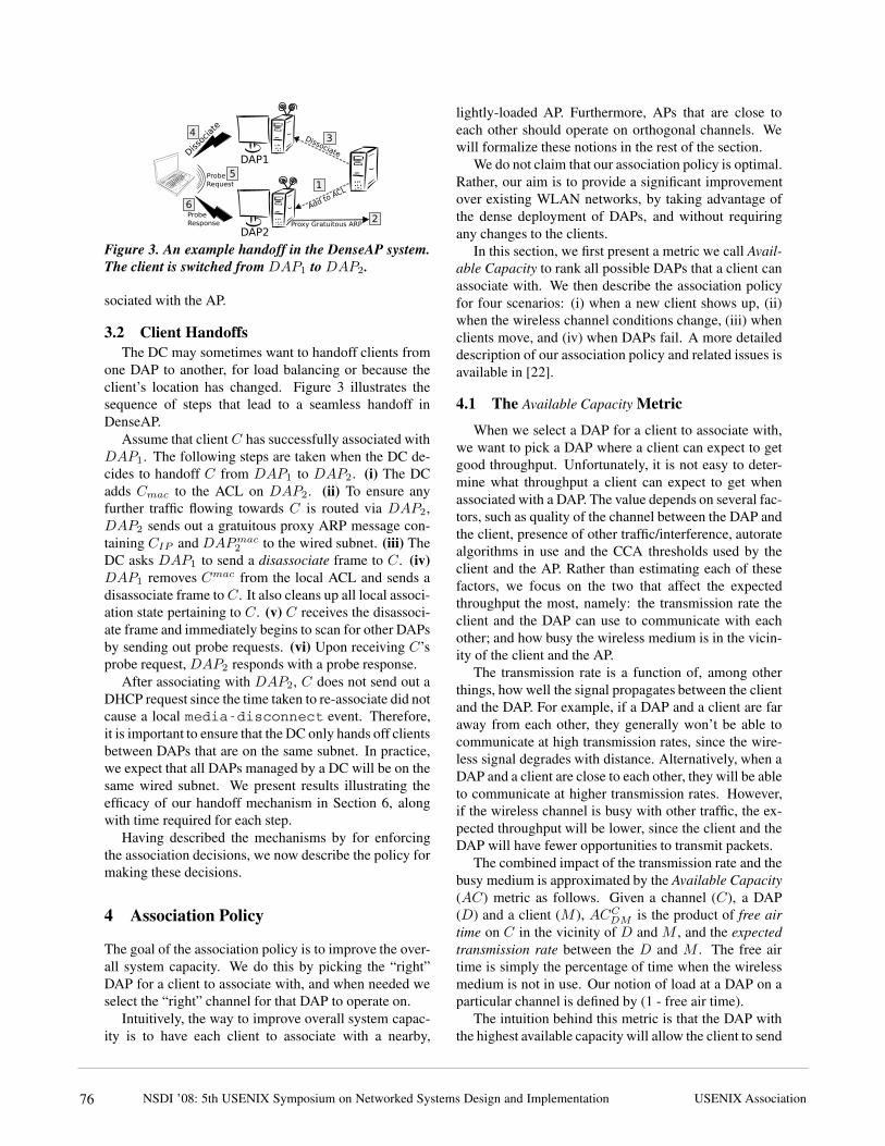
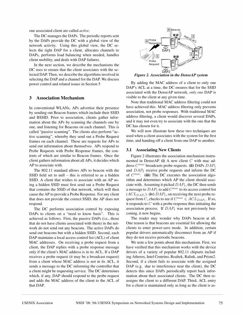
Figure 3. An example handoff in the DenseAP system.The client is switched from DAP1 to DAP2.
sociated with the AP.
3.2 Client HandoffsThe DC may sometimes want to handoff clients from
one DAP to another, for load balancing or because theclient’s location has changed. Figure 3 illustrates thesequence of steps that lead to a seamless handoff inDenseAP.
Assume that client C has successfully associated withDAP1. The following steps are taken when the DC de-cides to handoff C from DAP1 to DAP2. (i) The DCadds Cmac to the ACL on DAP2. (ii) To ensure anyfurther traffic flowing towards C is routed via DAP2,DAP2 sends out a gratuitous proxy ARP message con-taining CIP and DAPmac
2to the wired subnet. (iii) The
DC asks DAP1 to send a disassociate frame to C. (iv)DAP1 removes Cmac from the local ACL and sends adisassociate frame to C. It also cleans up all local associ-ation state pertaining to C. (v) C receives the disassoci-ate frame and immediately begins to scan for other DAPsby sending out probe requests. (vi) Upon receiving C’sprobe request, DAP2 responds with a probe response.
After associating with DAP2, C does not send out aDHCP request since the time taken to re-associate did notcause a local media-disconnect event. Therefore,it is important to ensure that the DC only hands off clientsbetween DAPs that are on the same subnet. In practice,we expect that all DAPs managed by a DC will be on thesame wired subnet. We present results illustrating theefficacy of our handoff mechanism in Section 6, alongwith time required for each step.
Having described the mechanisms by for enforcingthe association decisions, we now describe the policy formaking these decisions.
4 Association Policy
The goal of the association policy is to improve the over-all system capacity. We do this by picking the “right”DAP for a client to associate with, and when needed weselect the “right” channel for that DAP to operate on.
Intuitively, the way to improve overall system capac-ity is to have each client to associate with a nearby,
lightly-loaded AP. Furthermore, APs that are close toeach other should operate on orthogonal channels. Wewill formalize these notions in the rest of the section.
We do not claim that our association policy is optimal.Rather, our aim is to provide a significant improvementover existing WLAN networks, by taking advantage ofthe dense deployment of DAPs, and without requiringany changes to the clients.
In this section, we first present a metric we call Avail-able Capacity to rank all possible DAPs that a client canassociate with. We then describe the association policyfor four scenarios: (i) when a new client shows up, (ii)when the wireless channel conditions change, (iii) whenclients move, and (iv) when DAPs fail. A more detaileddescription of our association policy and related issues isavailable in [22].
4.1 The Available Capacity Metric
When we select a DAP for a client to associate with,we want to pick a DAP where a client can expect to getgood throughput. Unfortunately, it is not easy to deter-mine what throughput a client can expect to get whenassociated with a DAP. The value depends on several fac-tors, such as quality of the channel between the DAP andthe client, presence of other traffic/interference, autoratealgorithms in use and the CCA thresholds used by theclient and the AP. Rather than estimating each of thesefactors, we focus on the two that affect the expectedthroughput the most, namely: the transmission rate theclient and the DAP can use to communicate with eachother; and how busy the wireless medium is in the vicin-ity of the client and the AP.
The transmission rate is a function of, among otherthings, how well the signal propagates between the clientand the DAP. For example, if a DAP and a client are faraway from each other, they generally won’t be able tocommunicate at high transmission rates, since the wire-less signal degrades with distance. Alternatively, when aDAP and a client are close to each other, they will be ableto communicate at higher transmission rates. However,if the wireless channel is busy with other traffic, the ex-pected throughput will be lower, since the client and theDAP will have fewer opportunities to transmit packets.
The combined impact of the transmission rate and thebusy medium is approximated by the Available Capacity(AC) metric as follows. Given a channel (C), a DAP(D) and a client (M ), ACC
DMis the product of free air
time on C in the vicinity of D and M , and the expectedtransmission rate between the D and M . The free airtime is simply the percentage of time when the wirelessmedium is not in use. Our notion of load at a DAP on aparticular channel is defined by (1 - free air time).
The intuition behind this metric is that the DAP withthe highest available capacity will allow the client to send
4NSDI ’08: 5th USENIX Symposium on Networked Systems Design and Implementation USENIX Association76

the most data, while simultaneously reducing the impacton other clients in the network. For example, if a clientand DAP can communicate at a high transmission rate,then each frame will consume less air time, and the clientwill be able to send more data. Furthermore, other clientson the same channel in the vicinity will have more oppor-tunity to transmit. On the other hand, if the channel haslow utilization then it is acceptable for the client and theDAP to communicate at a low transmission rate becauseit will have little impact on other clients.
This metric is similar to the one proposed in [10],where clients associate with the AP which is the leastloaded and offers the best data rate. We compare andcontrast our work with [10] in more detail in Section 8.
We now describe how we estimate the free air timeand the expected data rate for a given DAP/client pair.We stress that we do not expect these calculations to beprecise. Our intention is to provide a reasonable orderingof DAPs, in order to pick a good AP for the client to as-sociate with. The load balancing process described laterin the section can reassign the client to a different DAP,should the conditions change and the initial choice is nolonger appropriate.
4.1.1 Estimating Free Air Time
Given a dense deployment of DAPs, it is likely thatthe DC will associate a client with a nearby DAP. Hence,it is also likely that the wireless channel conditions nearthe DAP and the client associated with it will be similar.Thus, we only estimate the free air time on a channel inthe vicinity of the DAP.
The amount of free air time around the DAP dependson the traffic generated by the DAP itself (i.e. down-link traffic), the uplink traffic and any background traf-fic/interference. The background traffic includes trafficgenerated by other DAPs and clients in the vicinity thatare functioning on the same channel. Of these quanti-ties, the DAP can easily determine the amount of air timeconsumed by the traffic it generates. To determine therest, we have devised a method inspired by the Probe-Gap technique [16].
Each DAP periodically sends a small broadcast packetat a fixed transmission rate on the highest priority driverqueue, which is usually reserved solely for high priorityPSM packets. The packets in this queue are sent evenif the DAP has other packets pending in the normal dataqueue.
The DAP records the difference in time from whenthe packet was queued to when the transmit completioninterrupt signals that the frame was successfully sent.When the channel is idle, the packet will be transmittedimmediately and the measured delay will be the sum offrame transmission time plus various OS overheads. Wedenote this value by δmin. Because the channel is idle,
0
20
40
60
80
100
0 2 4 6 8 10 12 14 16 18 20
Estim
ated
free
air
time
(%)
Traffic (Mbps)
Calculated from traceEstimated by ProbeGap
Figure 4. Validation of ProbeGap method
δmin does not depend on channel conditions. The trans-mission time of the frame is determined by the transmis-sion rate and the size of the packet, both of which areconstant. The OS overheads depend on the hardware andsoftware configuration of the DAP. If the channel is busy,the packet will be delayed by more than δmin. This ad-ditional delay depends on several factors such as numberof contending stations, the size of packets they are send-ing and their transmission rates. To obtain a good esti-mate of the fraction of time the channel is busy, we senda number of such probe packets and count the fractionof packets that experienced a delay of more than δmin.Because δmin does not depend on channel conditions, itcan be calculated apriori by performing simple calibra-tion experiments.
This technique works quite well in practice, as shownin Figure 4. The experiment was performed as follows.We set up a DAP with no associated clients on an oth-erwise idle channel in the 802.11a band. We had previ-ously determined that δmin was 250 microseconds. Us-ing another AP and a client, we generated different vol-umes of CBR UDP traffic on the channel. We had also setup a sniffer to capture every packet. This graph shows theamount of free air time estimated by the DAP, as well asthe “actual” free air time calculated using the trace cap-tured by the sniffer. We see that the estimate provided byour method is a good approximation, although we tendto slightly underestimate the free air time.
Note that the probe packets are not delayed by the nor-mal data traffic generated by the DAP itself (i.e. down-link traffic). So, to estimate the free air time, the DAPadds the air time consumed by the traffic it generates tothe estimate obtained by the ProbeGap method before re-porting it to the DC.
If a DAP has clients associated with it, it only needsto report the free air time for the channel it is currentlyon. If a DAP has no associated clients, it can scan allchannels and report to the DC the channel that has themost free air time.
In our current implementation, each DAP sends theload estimation probes every 200ms. The free air time isestimated over a period of 20 seconds.
5
NSDI ’08: 5th USENIX Symposium on Networked Systems Design and ImplementationUSENIX Association 77

4.1.2 Estimating Expected Transmission Rate
It is difficult to accurately predict the transmission ratea client will achieve when communicating with a DAP(or vice-versa). The rate primarily depends on how wellthe DAP receives the client’s signal. However, the ratealso depends on a variety of other factors such as the au-torate algorithm implemented by the client, power levelsused by the client, and channel conditions near the client.Of these factors, we can only estimate how well the DAPreceives a client’s signal.
When attempting to associate, clients send out proberequest messages which are overheard by nearby DAPswho then inform the central controller. We estimate thequality of the connection between the client and the var-ious candidate DAPs using the signal strength (RSSI) ofthe received probe request frames at the various DAPs.We convert these observed signal strengths into estimatesof expected transmission rate by using a mapping table.The mapping table bucketizes RSSI values into fixed-size buckets, and assigns an expected rate to each bucket.We assume that the same transmission rate will be usedby both the client and the AP. We call this the rate-mapapproach. The mapping table is initially generated bymanual profiling using a few clients at various locations.It can then be refined as actual data from more clients isgathered during live operation.
At first glance, it may appear that extrapolating thesignal strength observed in the uplink direction to an ex-pected transmission rate in both directions could resultin inaccurate estimations and/or poor performance, es-pecially considering the other factors that are ignored.Yet, in our system, we find that it provides reasonableresults for the following reasons. First, given the den-sity of access points, a client generally associates with anearby DAP. For such short distances, we find that signalstrength measured in one direction is a good approxima-tion of signal strength seen in the other direction. Sec-ond, because the client and the DAP are usually closeto each other, we generally see good signal strength inboth directions. Most commercial Wi-Fi cards behavesimilarly in such conditions. Finally, note that we donot need the exact transmission rates used by either theclient or the DAP. The conversion table is merely a wayto ranking the relative importance of the observed sig-nal strength. In Section 6, we will present results thatdemonstrate the usefulness of the rate-map approach.
We now describe how the AP selection algorithm usesthe available capacity metric.
4.2 Associating a New Client
When a new client first appears in the network, itscans on all channels and sends out probe requests. Be-cause this client has not yet been added to the ACL of any
DAP, all DAPs that hear the probe requests simply reportthem to the DC. To calculate reasonable signal strengthestimates, the DC waits for a short while (10-30 secondsin our current implementation) after the first report of anew client is received. During this interval it continuesto collect reports of probe request packets from DAPs.At the end of this interval the DC calculates the averagesignal strength of all the probe request frames seen byeach DAP. The rest of association algorithm is illustratedby the following example.
Assume two DAPs, A and B hear probe requests froma client M . Assume that A is active i.e. it already hasother clients associated with it, whereas B does not (pas-sive). For both A and B, the DC first calculates the ex-pected rates with M , RAM and RBM , using both the ob-served signal strengths and the rate map table. Then, theDC considers the amount of free air time at each DAP.A already has clients associated with it, and thereforeit is operating on some channel X . Hence, A has al-ready been reporting free air time for that channel. Wedenote this by FXA. Using the most recent report, theDC calcuates the available capacity at A on channel X
by ACXAM
= FXA ∗ RAM .Now let us consider DAP B. It has no clients associ-
ated with it. Let us assume that DAP B has recently seenthe highest available free air time on channel Y , denotedby FY B . The DC calculates the available capacity at B
on channel Y as ACYBM
= FY A ∗ RBM . The DC thencompares ACX
AMand ACY
BM, and picks the higher of
the two. If they are equal, it decides in favor of B, sinceB has no clients associated with it. In general, when-ever available capacity of several DAPs are equal, theDC always picks one that has the fewest clients associ-ated with it. If the DC picks A, it adds M ’s mac addressto A’s ACL. If it picks B instead, it first instructs B tostop scanning and to stay on channel Y . It then adds M ’smac address to B’s ACL. In both cases, the rest of the as-sociation process unfolds as described in Section 3.1.
Note two key aspects of this algorithm. First, wenever move existing clients to another DAP as a resultof a new client association. Second, DAPs are only as-signed channels on an on-demand basis, as part of theassociation process. A DAP is assigned a channel onlywhen a client in its vicinity requests service from the net-work. When a DAP becomes passive, it no longer has anassigned channel.
4.3 Load Balancing
The goal of the load balancing algorithm is to detectand correct overload situations in the network. We expectthat such situations will be rare in an environment witha dense deployment of access points, and with numerousavailable orthogonal channels (e.g. 12 in 802.11a). How-ever, it is important to watch for, and correct the overload
6NSDI ’08: 5th USENIX Symposium on Networked Systems Design and Implementation USENIX Association78

situations if and when they occur.For example, an overload situation might occur if
many clients congregate in a conference room, and thenetwork conditions are such that the algorithm describedin Section 4.2 assigns several of them to a single DAP. Insuch a situation, all clients simultaneously transmittingor receiving data can cause an overload at the DAP.
The load balancing algorithm works as follows. Onceevery minute, the DC checks all DAPs to see if any areseverely overloaded. Recall from Section 4.1.1 that thebusy air time (load) calculation incorporates the impactof traffic/interference near the DAP and the downlinktraffic generated by the DAP. We consider a DAP to beoverloaded, if it has at least one client associated withit, and it reports free air time of less than 20%. In otherwords, the channel is more than 80% busy in the vicinityof this DAP. The DC considers the DAPs in the decreas-ing order of load. If an overloaded DAP (A) is found,the DC considers the clients of A as potential candidatesto move to another DAP. Recall that the DAPs send pe-riodic summaries of client traffic to the DC. These sum-maries include, for each client, a smoothed average of thesum of uplink and downlink traffic load generated by theclient during the previous interval. The load is reportedin terms of air time consumed by the traffic of this client,and the average transmission rate of the traffic.
For each client M ∈ A, the DC attempts to find aDAP B such that the expected rate M will get at B is noless than the average transmission rate of the client at A,and the free air time at B is at least 25% more than the airtime consumed by M at A. If such a DAP is found, M ismoved to B using the process described in Section 3.2.Note that if B had no clients associated with it, the DCwill also assign it a channel (the one B reported to havethe most free air time on), just as it would do when asso-ciating a new client.
The load balancing algorithm moves at most oneclient that satisfies the above criteria during each itera-tion. Furthermore, once a client M has been handed offfrom A to B, it is considered ineligible to participate inthe next round of load balancing. These hysteresis tech-niques are intended to prevent oscillations.
We note a few things about the load balancing algo-rithm. (i) Our algorithm is conservative. Moving clientsfrom one AP to another is a potentially disruptive event,and we try to minimize how often we force such reas-sociations to occur. (ii) The load balancing algorithmimproves overall system throughput in two ways. First,the client that is moved to the less-loaded AP can rampup and consume more bandwidth. Second, the clientsthat stayed with the previously overloaded AP now haveone less client to contend with, and they can also in-crease their throughput. (iii) It is sometimes possible todo load balancing by changing the channel of the over-
loaded DAP. This technique is useful only if the back-ground traffic/interference (potentially from other DAPs)on the channel is significantly higher compared to thetraffic sent/received by the overloaded DAP itself. How-ever, the drawback of this technique is that all clients as-sociated with the DAP will have to to re-associate. Sincewe consider client re-associations to be disruptive events,we do not to use this technique.
4.4 Mobility
The DC keeps track of a client’s location, using thealgorithm described in [11]. The algorithm takes into ac-count the signal strength of a client’s transmissions as re-ported by various DAPs, and the location of those DAPs,to determine the approximate location of the client. Themedian location error is about 1.5 meters. This is suffi-cient for our purpose because we only need to detect thatthe client’s location has changed significantly.
The DC updates the locations of clients in the systemevery 30 seconds. When a client’s location changes bymore than 10 meters, the DC finds another DAP for theclient to associate with, using the criteria described inthe previous section. If such a DAP is found, the clientis handed off to the new DAP. A client that undergoeshandoff is considered ineligible to participate in the sub-sequent round for load balancing to prevent oscillations.It is, however, eligible to participate in another, mobility-related handoff.
4.5 Fault Tolerance
DAPs send periodic reports to the DC, so it is easyfor the DCto detect when a DAP fails. In our currentimplementation, if the DC does not receive any reportsfrom a DAP for up to one minute, it flags the DAP asa possible failure and does not assign any new clientsto it. The clients associated with the failed DAP get dis-connected. These clients immediately begin scanning forother DAPs in the vicinity by sending out probe requestmessages. Other DAPs in the vicinity pick up these probemessages and alert the central controller, which assignsthese clients to other DAPs, as per the association pol-icy.
5 Power Control
In a dense deployment of DAPs, transmit power controlcan mitigate the effects of interference between DAPs onthe same channel [20], and increase spatial reuse. Sincewe do not wish to modify clients, we must do do powercontrol at DAPs alone. However, such unilateral powerlevel can cause the clients and APs to operate at differenttransmit power levels. Prior work [20] has shown that
7NSDI ’08: 5th USENIX Symposium on Networked Systems Design and ImplementationUSENIX Association 79
Figure 5. The network stack on each DenseAP node
asymmetric transmit power levels can increase the num-ber of hidden terminals in a WLAN coverage area.
We have implemented and tested several adaptivepower management schemes in our testbed. We do notpresent detailed results due to lack of space. Briefly, ourresults confirm the observations in [20]. Based on theseresults, as well as those reported in prior work, we con-clude that unilateral power control at DAPs is undesir-able, and the best policy is to simply use the maximumpower level. A secondary benefit of this scheme is that itprovides better coverage in the intended coverage area.
Two other parameters that can also affect the over-all WLAN capacity are the Clear Channel Assessment(CCA) threshold used by each DAP [19], and the au-torate algorithm implemented on each DAP. The wirelesscards we used in our testbed do not allow us to changethe CCA threshold. Auto-rating algorithms have beenstudied extensively by prior research. DenseAP nodesuse the autorate algorithm described in [25].
6 Evaluation
We have built a prototype implementation of theDenseAP system. Figure 5 illustrates the network stackon each DAP. The network stack enables AP functional-ity on ordinary desktop machines. An integral part of thestack is our software AP (SoftAP), a fully programmableAP for the Windows platform. The wired and wirelessinterfaces are bridged. Each DAP also runs a DenseAPdaemon, a user-level service responsible for managinglocal access point functionality. The service periodicallyqueries the SoftAP driver, and sends summaries of clientstatistics to the DC. It also receives commands from theDC and sets appropriate parameters in the driver.
The DAPs are off-the-shelf PCs running WindowsVista, and the networking stack described above. Eachmachine is equipped with a Netgear JWAG511 wirelessNIC. The wireless NICs are based on a chipset from Re-alTek. They support operation in 802.11 a/b/g modes,with one limitation: in the 802.11a mode, they can oper-ate only on the lower 8 channels (channels 36-64). Wealso found that the RealTek cards do not work reliably
Figure 6. The testbed. The area is roughly 32m x 35m.The rooms have full walls, and solid wood doors.
in promiscuous mode, so we use an additional radio oneach DAP to simulate promiscuous mode. This secondradio is not fundamental to our approach, and is usedonly to compensate for the shortcomings of the RealTekcard. All of the DAPs are connected to the same IP sub-net on their wired Ethernet link. The DC is an ordinarydesktop-class machine.
The DenseAP testbed is deployed on a portion of ouroffice floor, as shown in Figure 6. The testbed consistsof 24 DAPs. The DAPs are deployed roughly in everyother office. Within each office, the machine is placed onthe floor; the exact location determined by the consentof the occupant. This area of our building is served by asingle corporate WLAN AP. The AP is located roughly atthe center of the area, and is placed on the ceiling. Notethat the DenseAP deployment is 24 times denser than thecorporate WLAN. In addition to the DAPs, we have alsodeployed 24 machines to serve as clients. The clients area mix of ordinary desktop and laptop machines, equippedwith a variety of off-the-shelf wireless NICs.
Most of the the experiments reported in this paperwere run in 802.11a mode (5 GHz band). There is verylittle corporate traffic in the 802.11a band. Thus, for mostexperiments, the background traffic is negligible, and wedid not need to run the load estimation algorithm. The802.11g band does see a fair amount of usage during nor-mal office hours, but to avoid impacting corporate traf-fic, we were limited to conducting 802.11g experimentsoutside of normal work hours. We now turn to evaluat-ing the performance of the DenseAP system using thistestbed. We begin by validating the rate-map approach(section 4.1.2), which lies at the heart of our associationand load balancing algorithms.
6.1 Usefulness of Rate-Map Approach
The rate-map approach (section 4.1.2) is the founda-tion of the association and load balancing algorithms.This approach is based on the hypothesis that the sig-
8
NSDI ’08: 5th USENIX Symposium on Networked Systems Design and Implementation USENIX Association80

nal strength of a client’s probe request packets, as ob-served by a DAP (i.e. uplink packets), is a good approx-imation of the transmission rate a client can expect inboth the up link and downlink directions in a dense DAPdeployment. Higher transmission rates, generally implyhigher throughput between the corresponding DAP andthe client. Hence, the objective of the rate-map approachis to pick a DAP such that a client will get good through-put in both directions.
To validate our hypothesis we demonstrate a positivecorrelation between the RSSI of the probe request pack-ets from the client to both uplink and downlink through-put via the following experiment. We set up a client lap-top at a fixed location. The client attempts to associatewith each of the 24 DAPs in turn. Prior to each associa-tion attempt with a DAP, we measure the signal strengthof the client’s probe request packets as observed at thatnode. This is the uplink signal strength (USS). After as-sociating with a DAP, the client contacts a server on thewired network, and carries out a 2 minute TCP down-load, followed by a 2 minute TCP upload. We carryout this experiment from 6 different locations, and re-peated the entire process 5 times. The experiment wasperformed on channel 64 of 802.11a band.
We found a correlation of 0.71 between USS and up-load throughput and 0.61 between USS and the down-load throughput. These results indicate that USS can beindeed be used as a good predictor of upload and down-load throughput. This correlation is much stronger if welook at the throughput numbers against bucketized USSvalues. The rate-map approach bucketizes USS valuesand assigns a rate to each bucket (section 4.1.2). Fig-ure 7 illustrates the strong correlation between through-put numbers and these bucketized USS values. The errorbars indicate one standard deviation. It can be seen thatthe bucketized USS values are a good predictor of bothupload and download throughput.
We have conducted these measurements over a num-ber of clients and consistently found positive correla-tions thereby validating the hypothesis that USS valuesof probe packets from clients, can be used as good prox-ies for transmission rates between a DAP and the client.
Note that we have demonstrated a correlation betweenUSS and uplink and downlink throughput. Detailed re-sults that demonstrate a correlation between USS andtransmission rates are available in [22].
6.2 DenseAP Performance
We now present results that demonstrate the perfor-mance of the DenseAP system. We first establish thebaseline for all our experiments. We then demonstratethe overall gains achieved by DenseAP and present a se-ries of experiments that delineate the contribution of var-ious facets of the DenseAP system to those gains. We
0
5000
10000
15000
20000
40+30-3920-2910-190-9Aver
age
per-c
lient
thro
ughp
ut (K
bps)
RSSI values
UploadDownload
Figure 7. Correlation between bucketized uplink RSSIand upload/download throughput
also demonstrate graceful degradation of the system’sperformance when the number of clients increases orwhen number of DAPs decrease. Since a large majorityof the traffic in WLANs tends to be downlink [11], weonly present downlink numbers for most experiments.We have conducted uplink experiments in each case, andfound the uplink results to be very similar to the down-link results.
6.2.1 Establishing the Baseline
We begin by evaluating the performance of the corpo-rate WLAN, to provide a baseline against which we cancompare the performance of our system.
As mentioned earlier, the testbed area is served bya single corporate AP. To establish the baseline perfor-mance, we had a group of clients associate with thecorporate AP. The clients then simultaneously carriedout a one minute TCP download from a server on thewired network. We varied the group size (the numberof clients) from 2 to 12. The experiment is repeated 10times for each group size. Each time, the group membersare selected at random from among the available clients.We performed similar experiments for upload.
The results of this experiment are shown in Fig-ures 8 and 9. Each point represents the median per-clientthroughput, and the error bars show SIQR.
For both 802.11a and 802.11g, the median per-clientthroughput drops as number of simultaneously activeclients increases. However, the 802.11g numbers aresubstantially lower than the 802.11a numbers. This isbecause in 802.11g mode, the corporate AP sends out aCTS-to-self before every packet to avoid interfering with802.11b clients. This is a well-known, and well-studiedissue. Since we have not implemented the CTS-to-selffeature for DAPs, we will refrain from directly compar-ing the performance of DenseAP and the corporate net-work in 802.11g mode.
6.2.2 Overall DenseAP Performance
We now repeat the experiment described in the pre-vious section, but using the DenseAP system instead of
9
NSDI ’08: 5th USENIX Symposium on Networked Systems Design and ImplementationUSENIX Association 81

0
5000
10000
15000
20000
0 2 4 6 8 10 12
Per-c
lient
thro
ughp
ut (K
bps)
Simultaneously active clients
UploadDownload
Figure 8. Baseline performance: 802.11a
0
5000
10000
15000
20000
0 2 4 6 8 10 12
Per-c
lient
thro
ughp
ut (K
bps)
Simultaneously active clients
UploadDownload
Figure 9. Baseline performance: 802.11g
corporate WLAN. All features such as channel assign-ment, association policies and load balancing were en-abled. We repeated the experiment twice in 820.11amode, once using 8 channels (channels 36-64) and onceusing 4 channels (channels 40, 48, 56 and 64) We alsoran the experiment with the DenseAP system in 802.11gmode using 3 orthogonal channels (channels 1, 6 and 11).
Figure 10 illustrates the performance of DenseAP inthe 802.11a band. Figure 11 illustrates the performanceof DenseAP in the 802.11g band. The graph does nothave a baseline, since we do not wish to compare per-formance of corporate WLAN and DenseAP in 802.11gmode, as explained earlier. Let us focus on the 802.11aresults.
We see significant performance gains over the corpo-rate network. For example, with 8 simultaneously activeclients, the median download throughput on the corpo-rate network was 1.3Mbps. On the other hand, the me-dian download throughput with DenseAP when using 8channels, was 11.25Mbps. This represents an improve-ment in capacity by a factor of 868% over the corporateWLAN. Similarly, for 12 clients in the system, the me-dian download throughput for corporate WLAN is 750Kbps and for DenseAP it is 9.4 Mbps, which is an im-provement of over 1250%.
The the comparison with the corporate WLAN mayseem unfair, because we are comparing the 8-channel,24-AP DenseAP system against a single-channel, single-AP baseline. However, the only purpose of these resultsis to show the full benefit of the DenseAP approach in
0
5000
10000
15000
20000
0 2 4 6 8 10 12
Per-c
lient
thro
ughp
ut (K
bps)
Simultaneously active clients
DenseAP (11a, 8 Chan.)DenseAP (11a, 4 Chan.)
Corp WLAN (11a)
Figure 10. DenseAP performance: 802.11a
0
5000
10000
15000
20000
0 2 4 6 8 10 12
Per-c
lient
thro
ughp
ut (K
bps)
Simultaneously active clients
DenseAP (11g, 3 Chan.)
Figure 11. DenseAP performance: 802.11g
our testbed. The next step is to separate out the impactof various factors that contribute to these results. As de-scribed earlier, the gain in throughput comes from fourfactors. These are: (i) use of orthogonal channels (ii)dense deployment of APs (iii) use of intelligent associa-tions and (iv) load balancing.
We note that though enabled, the load balancing algo-rithm played no role in these results. The main reason isthat the clients are scattered uniformly across the floor.Thus, in most cases, each client associated with its ownDAP. Further, since all clients started at the same timeand they all saturated their respective channels, there wasno opportunity for our load balancing algorithm to movea client from one DAP to another since all channels wereequally loaded. We consider the impact and efficacy ofthe load balancing algorithm later in Section 6.3.
It is easy to see that more orthogonal channels are bet-ter, since the median throughput is higher with 8 chan-nels than with 4 channels. But the important question iswhether the DenseAP system derives all its benefit fromusing more orthogonal channels? That is, can we iso-late the impact of the dense deployment of DAPs andour centralized association policy?
To isolate the impact of DAP density, we need to en-sure that the number of channels and the association pol-icy play no role in the performance. The way to do this isto evaluate the performance of the DenseAP system withall DAPs operating on the same channel. This experi-ment is described next.
10NSDI ’08: 5th USENIX Symposium on Networked Systems Design and Implementation USENIX Association82
0
5000
10000
15000
20000
1 2 3 4 5 6Aver
age
per-c
lient
thro
ughp
ut (K
bps)
Numer of active clients
Corporate WLANDenseAP
Figure 12. Benefits of density: DenseAP with 1 channel
6.2.3 Using Only 1 channel: Impact of Density
We repeated the previously described experiment withonly one channel, and we varied the number of activeclients from one to six. We did the experiment for thecorporate WLAN, and then repeated it for DenseAP withall DAPs set to use the same channel.
Note that association policy plays very little role inthis setting. Our testbed is small, and all DAPs inter-fere with one another. As a result, load on all DAPs isthe same, so the association policy is reduced to simplyselecting a DAP that hears the client with reasonable sig-nal strength. For similar reasons, load balancing does notplay a role either.
Thus, the only factor providing gains for DenseAPin this setting is the density of the DAPs. The reasondensity provides performance gains in this setting is thefollowing. As more clients are added, the performanceof the corporate WLAN is dominated by the client withthe worst connection quality, which is usually the clientthat is the farthest away from the AP. Due to poor con-nection quality, such clients use lower transmission rates,thereby consuming more airtime. This, in turn, hurts per-formance of all other clients. This is known as the rateanomaly problem [13]. With DenseAP however, eachclient generally talks to a nearby DAP. As a result, clientsand DAPs can communicate at higher data rates, therebyreducing the impact of the rate anomaly problem.
The results of this experiment are shown in Figure 12.We see that DenseAP performs better than WLAN evenin this setting. The results highlight the benefit of thedense AP deployment. They also explain why, in theprevious section, we saw gains of more than 800% with8 channels!
The results lead us to ask: can a system administra-tor significantly improve capacity by simply adding moreAPs to the network? In other words, what is the contri-bution of the association policy to the overall gain? Weexamine this in the next section.
6.2.4 Benefits of Association Policy
In this section we demonstrate the benefits ofthe DenseAP association policy over the client-drivenmethod of association used in conventional WLANs.
0
5000
10000
15000
20000
0 2 4 6 8 10 12
Per-c
lient
thro
ughp
ut (K
bps)
Simultaneously active clients
DenseAP (11a, 8 Chan.)Client-driven (11a, 8 Chan.)
Corp WLAN (11a)
Figure 13. Benefits of the association policy
0
20
40
60
80
100
0 2 4 6 8 10 12
Incr
ease
in p
er-c
lient
thro
ughp
ut (%
)
Simultaneously active clients
Figure 14. Gains over the client-driven approach
We carried out the following experiment in the802.11a band, using 8 channels. We disabled the DC. Wefirst assigned channels to all DAPs using the channel as-signment algorithm described in [15]. We then disabledthe ACLs, and allowed clients to associate with the DAPof their choice. In other words, the association decisionswere left to the clients (as it is in today’s WLANs). Thissetup represents a dense deployment with a conventionalWLAN approach. We then carried out the experimentdescribed in the previous section.
We note a few points about this particular scenario.There was no pre-existing traffic on any of the chan-nels. Also, the clients were generally evenly distributedacross the testbed, and so were the DAPs. Each clientthen picked the DAP to associate with based on the localclient driver implementation policies.
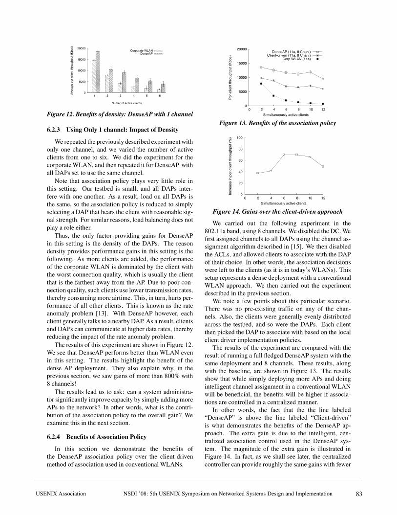
The results of the experiment are compared with theresult of running a full fledged DenseAP system with thesame deployment and 8 channels. These results, alongwith the baseline, are shown in Figure 13. The resultsshow that while simply deploying more APs and doingintelligent channel assignment in a conventional WLANwill be beneficial, the benefits will be higher if associa-tions are controlled in a centralized manner.
In other words, the fact that the the line labeled“DenseAP” is above the line labeled “Client-driven”is what demonstrates the benefits of the DenseAP ap-proach. The extra gain is due to the intelligent, cen-tralized association control used in the DenseAP sys-tem. The magnitude of the extra gain is illustrated inFigure 14. In fact, as we shall see later, the centralizedcontroller can provide roughly the same gains with fewer
11
NSDI ’08: 5th USENIX Symposium on Networked Systems Design and ImplementationUSENIX Association 83
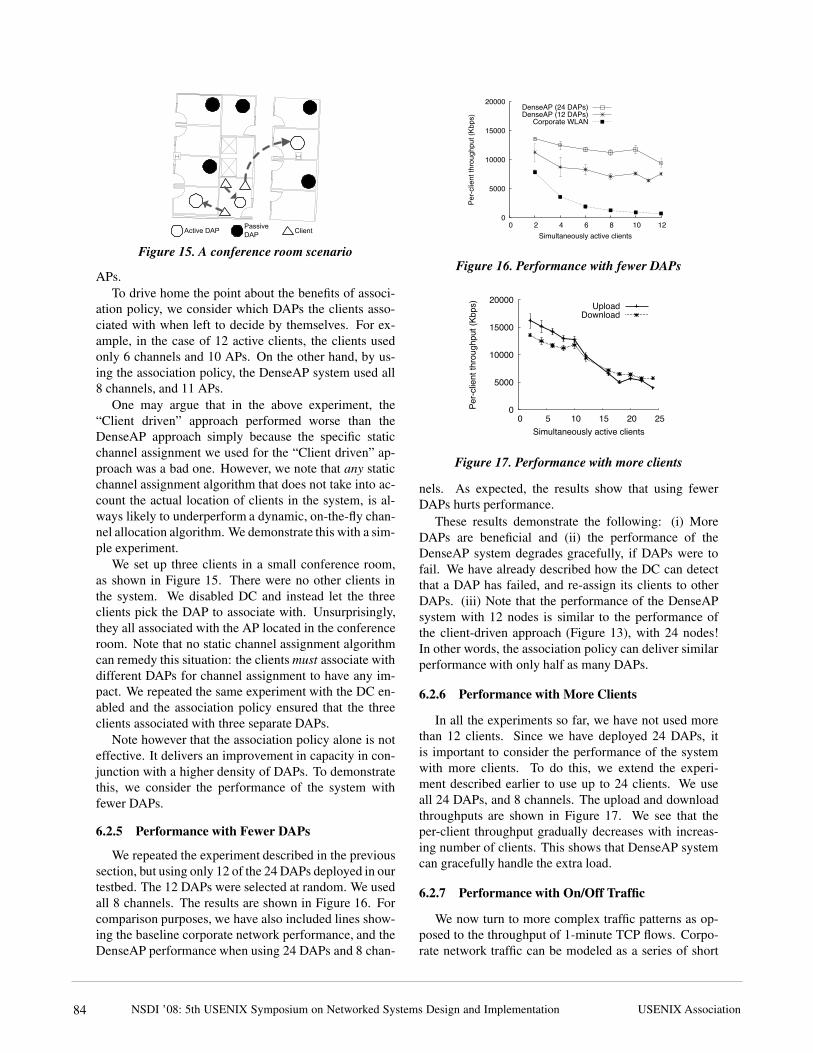
Figure 15. A conference room scenario
APs.To drive home the point about the benefits of associ-
ation policy, we consider which DAPs the clients asso-ciated with when left to decide by themselves. For ex-ample, in the case of 12 active clients, the clients usedonly 6 channels and 10 APs. On the other hand, by us-ing the association policy, the DenseAP system used all8 channels, and 11 APs.
One may argue that in the above experiment, the“Client driven” approach performed worse than theDenseAP approach simply because the specific staticchannel assignment we used for the “Client driven” ap-proach was a bad one. However, we note that any staticchannel assignment algorithm that does not take into ac-count the actual location of clients in the system, is al-ways likely to underperform a dynamic, on-the-fly chan-nel allocation algorithm. We demonstrate this with a sim-ple experiment.
We set up three clients in a small conference room,as shown in Figure 15. There were no other clients inthe system. We disabled DC and instead let the threeclients pick the DAP to associate with. Unsurprisingly,they all associated with the AP located in the conferenceroom. Note that no static channel assignment algorithmcan remedy this situation: the clients must associate withdifferent DAPs for channel assignment to have any im-pact. We repeated the same experiment with the DC en-abled and the association policy ensured that the threeclients associated with three separate DAPs.
Note however that the association policy alone is noteffective. It delivers an improvement in capacity in con-junction with a higher density of DAPs. To demonstratethis, we consider the performance of the system withfewer DAPs.
6.2.5 Performance with Fewer DAPs
We repeated the experiment described in the previoussection, but using only 12 of the 24 DAPs deployed in ourtestbed. The 12 DAPs were selected at random. We usedall 8 channels. The results are shown in Figure 16. Forcomparison purposes, we have also included lines show-ing the baseline corporate network performance, and theDenseAP performance when using 24 DAPs and 8 chan-
0
5000
10000
15000
20000
0 2 4 6 8 10 12
Per-c
lient
thro
ughp
ut (K
bps)
Simultaneously active clients
DenseAP (24 DAPs)DenseAP (12 DAPs)
Corporate WLAN
Figure 16. Performance with fewer DAPs
0
5000
10000
15000
20000
0 5 10 15 20 25
Per-c
lient
thro
ughp
ut (K
bps)
Simultaneously active clients
UploadDownload
Figure 17. Performance with more clients
nels. As expected, the results show that using fewerDAPs hurts performance.
These results demonstrate the following: (i) MoreDAPs are beneficial and (ii) the performance of theDenseAP system degrades gracefully, if DAPs were tofail. We have already described how the DC can detectthat a DAP has failed, and re-assign its clients to otherDAPs. (iii) Note that the performance of the DenseAPsystem with 12 nodes is similar to the performance ofthe client-driven approach (Figure 13), with 24 nodes!In other words, the association policy can deliver similarperformance with only half as many DAPs.
6.2.6 Performance with More Clients
In all the experiments so far, we have not used morethan 12 clients. Since we have deployed 24 DAPs, itis important to consider the performance of the systemwith more clients. To do this, we extend the experi-ment described earlier to use up to 24 clients. We useall 24 DAPs, and 8 channels. The upload and downloadthroughputs are shown in Figure 17. We see that theper-client throughput gradually decreases with increas-ing number of clients. This shows that DenseAP systemcan gracefully handle the extra load.
6.2.7 Performance with On/Off Traffic
We now turn to more complex traffic patterns as op-posed to the throughput of 1-minute TCP flows. Corpo-rate network traffic can be modeled as a series of short
12
NSDI ’08: 5th USENIX Symposium on Networked Systems Design and Implementation USENIX Association84

Mean Time Load Offered Corporate DenseAPb/w requests per node WLAN
Overload 0.5s 2Mbps 828ms 46msFull load 1s 1Mbps 187ms 46msLow load 2s 0.5Mbps 60ms 46ms
Table 1. Performance with On/Off traffic
flows arriving at various times [12]. The metric of inter-est for such traffic patterns is the flow completion time.
To compare the performance of DenseAP system withcorporate WLAN with such on/off traffic, we carry outthe following experiment. We use 12 clients, all of whichare active simultaneously. Each client downloads 2000files from a central server on the corporate network. Thesizes of files are chosen from a Pareto distribution withmean of 125KB and shape parameter of 1.5. The timebetween start of successive downloads is chosen from anexponential distribution with a given mean. By changingthe mean time between successive requests, we can con-trol the amount of offered load generated by each client.
We consider three scenarios. In the first scenario, themean interarrival time between successive downloads is0.5 seconds. This corresponds to a mean offered load ofabout 2Mbps per client. In Figure 8, we see that when12 clients are simultaneously active on the corporateWLAN, the median per-client throughput is 750Kbps.Thus, the 2Mbps offered load represents a heavy over-load of the corporate network. We similarly constructa fully loaded, and highly loaded scenario using meaninterarrival times of 1 and 2 seconds, respectively. Thedetails are shown in Table 1.
We repeat the experiment on corporate WLAN, aswell as the DenseAP system using 24 APs and 8 chan-nels. The median flow completion times under corporateWLAN, and DenseAP system are shown in Table 1. Wesee that the median flow completion time for corporateWLAN is very high under the overload and full load sce-narios. These high flow completion times are detrimentalto user experience. On the other hand, in DenseAP themedian flow completion time is essentially equal in allthree cases, since the load on the system is substantiallylower than its capacity.
6.3 Load Balancing
As we have discussed earlier, in our system, a densedeployment of DAPs, coupled with the association pol-icy limits the need for frequent load balancing. Our sys-tem uses load balancing only to correct severely imbal-anced client-DAP assignments, rather than as a meansto achieve “optimal” performance. The reason for thisis simple: every client-AP reassignment, no matter howcarefully done, carries with it the potential to disrupt aclient’s performance.
To illustrate the load balancing capabilities ofDenseAP, we carry out the following experiment. We use
0
5000
10000
15000
20000
0 30 60 90 120 150 180
Thro
ughp
ut (K
bps)
Time (seconds)
Client 1Client 2Client 3
Figure 18. Load balancing: 3 TCP downloads
0
5000
10000
15000
20000
0 30 60 90 120 150
Thro
ughp
ut (K
bps)
Time (seconds)
Client 1Client 2
Figure 19. Load balancing: 2 CBR UDP flows
three clients, situated in a conference room, as shown inFigure 15. We force the DC to initially assign all threeclients to the conference room DAP. The clients startsimultaneously downloading files from a server on thewired network. The DC correctly recognizes the over-load situation, and at 1 minute intervals, reassigns two ofthe associated clients to two nearby APs, and sets themto operate on different channels. As a result, the through-put of all three clients improves substantially. The resultsare shown in Figure 18.
A similar scenario is shown in Figure 19. We use onlytwo clients. We force the DC to associate both clients tothe same AP. The first client starts a CBR UDP downloadthat consumes 15Mbps. This roughly simulates stream-ing playback of a high quality video. However, this is notenough to saturate the DAP, and hence the DC does notmove either client. At time 50 the second client starts amovie download as well. After one minute, the DC de-tects that an overload situation has occurred and movesthe second client to a nearby DAP, and assigns it anotherchannel. The 1-minute hysteresis interval is a tunableparameter of our system, and depending on system con-figuration and desires of the user population, can be setto a smaller or a larger value.
We now examine the time taken for a handoff fromone DAP to another during load balancing. As we willsee in the next section, it has significant implications forhandling of mobile clients. Recall the sequence of stepsfor a handoff illustrated in Figure 3. The breakdown oftime taken by each of these steps is shown in Table 2.As it has been observed in prior work [23], we see thatclient scanning is the most expensive step during a hand-
13NSDI ’08: 5th USENIX Symposium on Networked Systems Design and ImplementationUSENIX Association 85

Step Time (ms)Disassociation 0Scanning time 1487.6Authentication 00.381
Association 00.689Total handoff time 1488.67
Table 2. Breakdown of a typical handoff in DenseAP.
Figure 20. Locations for mobility experiment
off. The 1.5 second delay may cause a TCP timeout, butwon’t break an existing connection. To mitigate the im-pact of such disruptions, our load balancing algorithmis very conservative, and moves clients only if they areassociated with an overloaded DAP. Such clients wouldgenerally be experiencing poor performance in the firstplace.
6.4 Mobility Experiments
In all the experiments described so far, the clients havebeen stationary. In this section, we consider how theDenseAP system performs with non-stationary clients.Non-stationary clients fall in two categories, nomadicand mobile.
Nomadic clients move from place to place, but spendsignificant time being stationary at each place. In cor-porate WLANs, most non-stationary clients are nomadicclients. A typical example of a nomadic client is an em-ployee who takes her laptop to various meetings. Fornomadic clients, the quality of connection they receivewhen they are ”on the move” is less important than thequality of connectivity they receive when they are sta-tionary.
The other type of non-stationary clients are mobileclients. A Wi-Fi VoIP phone user falls in this cate-gory. Such clients are rare in current WLANs, but arelikely to become more prominent in future [18]. Theseclients need seamless connectivity as they move. Forsuch clients, metrics such as delay jitter and smoothnessof handoff are more important than throughput. Provid-ing good service to mobile clients in a Wi-Fi network isan active topic of research.
Our system can handle both nomadic and mobileclients. We present results for nomadic clients here. The
0
5000
10000
15000
20000
Location 3Location 2Location 1
Med
ian
clien
t thr
ough
put (
Kbps
) Mobility support enabledMobility support disabled
Figure 21. Performance of nomadic client
results for mobile clients are omitted due to lack of space,and are available in [22].
Our system periodically determines the location ofeach client, and triggers reassociation if the client’s posi-tion has changed substantially. This works quite well fornomadic clients, since the clients are stationary for mostof the time. We demonstrate this with the following ex-periment.
We setup a client at location 1 on the map shown inFigure 20, and carried out ten 2MB TCP downloads froma server on the wired network. We then walked to loca-tion 2, waited for two minutes, and carried out the down-loads again. We performed a similar experiment at loca-tion 3. We repeated the experiment twice: once withoutmobility support and once with the support enabled.
The median throughput of the downloads, with andwithout mobility support is shown in Figure 21. We seethat with mobility support enabled, the DC correctly re-associates the client at each location, so its performancedoes not suffer. Without mobility support, the client con-tinues to be associated with the AP near location 1, andits performance suffers at locations 2 and 3.
6.5 System Scalability
Our architecture uses a central controller (the DC) tomanage the DAPs. Each DAPs sends periodic reports tothe DC. This raises scalability concerns. To address theseconcerns, we note that our DC was able to easily managea network of 24 DAPs and 24 clients, without any specialoptimizations. The CPU load on the DC never exceeded30%. We estimate that the amount of control traffic gen-erated by each DAP was less than 20Kbps. Thus, weestimate that a slightly more powerful DC could easilyhandle a network of about 100 DAPs, without any spe-cial optimizations. This should be enough to cover a floorof our office building.
We note here that it is not strictly necessary to use asingle central controller. What is necessary is the use ofglobal knowledge while making association and channelassignment decisions. In theory, the functionality of thecentral controller can be either be replicated, or even im-plemented in a fully distributed manner. The DAPs canexchange information with each other to gain a globalview of the network, and make appropriate decisions.
14
NSDI ’08: 5th USENIX Symposium on Networked Systems Design and Implementation USENIX Association86

However, this approach is more complex to implement,and has its own set of scalability concerns.
Another issue we must address is the impact of sev-eral DAPs in close vicinity, beaconing and sending probepackets. Our measurements show that in the commoncase, the impact on performance is less than 1%. Thisis due to two reasons. First, only active DAPs send bea-cons, and second, when we use multiple channels, thenumber of DAPs on any one channel is small.
7 Discussion
We now discuss some issues related to the DenseAP ar-chitceture.Density Re-visited: The density of DAP deploymentsaffects the performance of DenseAP. This raises someimportant questions that need to be addressed, (i) Whereshould the DAPs be placed? (ii) Is there a point at whichadding more DAPs to the system can hurt performance?(iii) How do we determine the minimum necessarydensity for a required level of service in a given envi-ronment? Guidelines developed for traditional WLANsoffer little help in answering these questions, since theyare generally developed with an aim of using as fewAPs as possible while maximizing the coverage area.Question (i) In our current testbed, we distributed theDAPs roughly uniformly in the given area. However, itmay be beneficial to deploy more DAPs near “hotspots”such as conference rooms. We are studying this ques-tion further. For (ii), thus far, we have demonstratedexploiting density to yield higher gains in capacity.However, with only a finite number of channels andno power control, we expect the benefits from densityto diminish beyond a certain point. Mhatre et al. [19]have presented a closed form solution for optimal APdensity by varying the CCA threshold, and we areworking on validating it on our testbed. To address (iii),we can integrate DAIR [8] with DenseAP to automat-ically determine RF Holes, i.e. regions with no coverage.
Hidden Terminal: The DenseAP system mightexacerbate the hidden terminal problem due to a greaternumber of parallel transmissions. We have not noticedthis effect in our testbed where all DAPs interfere witheach other. However, hidden terminals might be aconcern in larger testbeds. We are expanding our de-ployment to investigate this issue in detail. However, ourpreliminary insight is that the hidden terminal problemmight not be severe in the DenseAP scenario because ofthe capture effect [17]. In a dense deployment of DAPs,the clients are generally located very close to the DAPsthey are associate with. Furthermore, the signal in the 5GHz band fades rapidly in indoor environments therebyreducing the interference from far-away transmitters.
Therefore, we expect the capture effect to reduce theimpact of hidden terminal problems.
Spatial Reuse of Channels: When assigning a channelto a DAP, our algorithm can take into account the loadon all available channels. The load includes backgroundnoise, as well as traffic generated by other DAPs. Thus,we achieve spatial re-use whenever possible. Ouralgorithm, however, is not optimized to maximize spatialre-use.
Co-existence with Other Wi-Fi Networks: Sincewe can take the load on a channel into account whileassigning channels to DAPs, it is easy to see thatDenseAP can co-exist with other Wi-Fi networks. Forexample, if a nearby network is generating heavy trafficon a particular channel, the DenseAP system can detectit, and avoid assigning that channel to DAPs that arelikely to be affected by that network.
What is the Ideal Client-AP Assignment?: The idealclient-AP assignment depends on several issues, includ-ing traffic, background noise and environmental fac-tors that affect radio signal propagation. Currently, theDenseAP algorithm ignores the impact of hidden termi-nal issues, and focuses on avoiding problems such as rateanomaly and AP overloading. We make no claims thatour algorithm is optimal. In future, we plan to study theoptimality of our algorithm using simulations.
8 Related Work
There has been much prior work on WLAN channel as-signment and power control. Several of them [9, 24, 14,10, 7, 21] either require modifications to the client or tothe 802.11 standard. This makes them difficult to deploy.To the best of our knowledge, ours is the first proposal tobe built and deployed that performs intelligent associa-tions and deals with a dynamic operating wireless envi-ronment without requiring client modifications. Of theprior work in this area, we address two systems in partic-ular that come closest to DenseAP.
Similar to DenseAP, MDG [10] identifies intelligentchannel assignment, power control and client associa-tion as being key components of a systematic approachto increase the capacity of an 802.11 wireless network. Itstudies the interdependencies between these three knobsand identifies various situations in which a correct or-der of their application can increase network capacity.Furthermore, MDG modifies clients, and uses explicitfeedback and cooperation from them to perform efficientchannel assignment, power control and association. Incontrast to MDG, DenseAP does not require any modi-fications to the clients, and therefore explores a different
15
NSDI ’08: 5th USENIX Symposium on Networked Systems Design and ImplementationUSENIX Association 87

design space.SMARTA [7] is similar to DenseAP in that it uses
a centralized server to increase the capacity of a denseAP deployment without requiring client modifications.However, it uses a different approach. The central con-troller builds a conflict graph among the APs, and usesthis graph to tune the AP’s channel and transmit power.It does not manage client associations. There are twomain differences between SMARTA and DenseAP. First,DenseAP relies on correctly managing client associa-tions. We have shown that the benefits of a dense AP de-ployment is limited if clients are allowed to take associa-tion decisions. We have also shown that unilateral powercontrol (without client cooperation) can hurt the perfor-mance of the system. We also note that since SMARTAis evaluated entirely in simulations, we are unable to doa fair comparison of SMARTA with our scheme.
In [6], the authors propose using a centralizedscheduling mechanism to schedule downlink traffic in adense deployment of APs. The overall goal is to effi-ciently manage the data plane of an 802.11 deployment.The work is in progress and at the time of this submis-sion, the authors have not proposed a solution for man-aging the uplink traffic.
A host of products by networking startup compa-nies [3, 5, 2, 4, 1] are designed to manage AP deploy-ments in the enterprise. The exact details about how theirproducts work are difficult to obtain. However, most sys-tems seem to either ignore association control and loadbalancing, or they address such challenges by requiringusers to install custom drivers.
9 Conclusion
We have demonstrated that DenseAP improves the ca-pacity of an enterprise network. It achieves this by ex-ploiting DAP density via an intelligent association pro-cess that encompasses load balancing and dynamic chan-nel allocation. We have described the algorithms andmechanisms necessary to support unmodified clients,and shown significant benefits in a real testbed deploy-ment.
Acknowledgments
We thank Victor Bahl, Ratul Mahajan, Matt Welsh,Aditya Akella, Jon Crowcroft, Lili Qiu, Dina Katabi andthe anonymous reviewers for their helpful comments onearly drafts of this paper. We thank Mitesh Desai forhelping with the SoftAP implementation.
References
[1] Autocell, http://www.autocell.com.
[2] Bluesocket, http://www.bluesocket.com.[3] Enterprise solutions from aruba networks,
http://www.arubanetworks.com/solutions/enterprise.php.[4] Extricom, http://www.extricom.com.[5] Meru networks, http://www.merunetworks.com.[6] N. Ahmed, S. Banerjee, S. Keshav, A. Mishra, K. Papagiannaki,
and V. Shrivastava. Interference Mitigation in Wireless LANsusing Speculative Scheduling . In MobiCom, 2007.
[7] N. Ahmed and S. Keshav. SMARTA: A Self-Managing Architec-ture for Thin Access Points. In CoNEXT, 2006.
[8] P. Bahl, R. Chandra, J. Padhye, L. Ravindranath, M. Singh,A. Wolman, and B. Zill. Enhancing the Security of CorporateWi-Fi Networks Using DAIR. In MobiSys, 2006.
[9] P. Bahl, M. Hajiaghayi, K. Jain, V. Mirrokni, L. Qiu, and A. Se-beri. Cell Breathing in Wireless LANs: Algorithms and Evalua-tion. IEEE Transactions on Mobile Computing, 2006.
[10] I. Broustis, K. Papagiannaki, S. V. Krishnamurthy, M. Falout-sos, and V. Mhatre. MDG: Measurement-driven Guidelines for802.11 WLAN Design. In MobiCom, 2007.
[11] R. Chandra, J. Padhye, A. Wolman, and B. Zill. A Location-based Management System for Enterprise Wireless LANs. InNSDI, 2007.
[12] J. Eriksson, S. Agarwal, P. Bahl, and J. Padhye. Feasibility Studyof Mesh Networks for All-Wireless Offices. In MobiSys, 2006.
[13] M. Heusse, F. Rousseau, G. Berger-Sabbatel, and A. Duda. Per-formance anomaly of 802.11b. In Infocom, 2003.
[14] G. Judd and P. Steenkiste. Fixing 802.11 Access Point Selection.In SIGCOMM Poster Session, Pittsburgh, PA, July 2002.
[15] B.-J. Ko, V. Misra, J. Padhye, and D. Rubenstein. Distributedchannel assignment in multi-radio 802.11 mesh networks. InWCNC, 2007.
[16] K. Lakshminarayanan, V. N. Padmanabhan, and J. Padhye. Band-width Estimation in Broadband Access Networks. In IMC, 2004.
[17] J. Lee, W. Kim, S.-J. Lee, W. Kim, D. Jo, J. Ryu, T. Kwon, , andY. Choi. An Experimental Study on the Capture Effect in 802.11aNetworks. In WINTECH, 2007.
[18] M. Lopez. Forrester Research: The State of North AmericanEnterprise Mobility in 2006. December 2006.
[19] V. Mhatre and K. Papagiannaki. Optimal Design of High Density802.11 WLANs. In CoNEXT, 2006.
[20] V. Mhatre, K. Papagiannaki, and F. Baccelli. Inteference Mitiga-tion through Power Control in High Density 802.11 WLANs. InInfocom, 2007.
[21] A. Mishra, V. Brik, S. Banerjee, A. Srinivasan, and W. Arbaugh.A Client-driven Approach for Channel Management in WirelessLANs. In Infocom, 2006.
[22] R. Murty, R. Chandra, J. Padhye, A. Wolman, and B. Zill. De-signing High Performance Enterprise Wi-Fi Networks. TechnicalReport MSR-TR-2008-28, 2008.
[23] I. Ramani and S. Savage. SyncScan: Practical Fast Handoff for802.11 Infrastructure Networks. In Infocom, Miami, FL, March2005.
[24] A. Vasan, R. Ramjee, and T. Woo. ECHOS - Enhanced Capacity802.11 Hotspots. In Infocom, 2005.
[25] S. Wong, S. Lu, H. Yang, and V. Bharghavan. Robust rate adap-tation for 802.11 wireless networks. In MobiCom, 2006.
16
NSDI ’08: 5th USENIX Symposium on Networked Systems Design and Implementation USENIX Association88