Embed Size (px)
Citation preview
Designing Computer Systems
Building Blocks
08:44:28 PM 4 June 2013 BB-1 © Scott & Linda Wills
Designing Computer Systems
Building Blocks
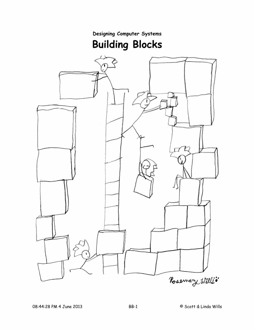
A logic gate employs many switches to achieve a more complex behavior. Now we’ll use gates to build an even more specialized, more powerful set of building blocks.
Encoders / Decoders: A binary digit or bit is the fundamental representational element in digital computers. But a bit by itself is limited to two states: O and 1. Fortunately, many bits can be grouped to form more interesting strings. This can be done in different ways. For example, three bits in a car might indicate whether (A) the door is open (B) the headlights are on, and (C) the seatbelt is fastened. These conditions are independent and can occur in any combination. So each bit in the string has a simple coding:
A door B headlights C seatbelt0 open 0 off 0 unfastened1 closed 1 on 1 fastened
In the transmission, three bits might represent its operation state:
C B A state0 0 0 neutral0 0 1 1st gear0 1 0 2nd gear0 1 1 3rd gear1 0 0 4th gear1 0 1 5th gear1 1 0 fault1 1 1 reverse
In this case, only one state can exist at a time. So rather than having eight separate bits to represent the transmission’s state, three bits are used to encode one of the eight possible states. This requires additional decoding when this information is used. In order to illuminate the “reverse” indicator on the dash board (and turn on the backup lights), all three bits are required to generate the control signal. A different set of values for A, B, and C indicates a different state. The Boolean expression for two of these states are:
Reverse = A · B · C 1st gear= A · B · C
The logic to decode these conditions from the three bits is shown below.
08:44:28 PM 4 June 2013 BB-2 © Scott & Linda Wills

Encoding things in this ways reduces the number of bits to be stored and communicated (a good thing). But it requires logic to decode a condition from that signal. Let’s explore a more common type of decoder: a multi-bit binary decoder.
N-to-M Binary Decoder: In many systems, it is useful to encode one of several states as a multi-bit binary number. In the transmission example, we used a three number value to represent on of eight conditions. More generally we can use N bits to represent 2N unique states. Although we can use logic to decode each state independently, we can envision a generic decoder that takes an N bit binary number as input, and produces M separate outputs. Here's a N to M decoder.
I0
I1
In-1
...
N-bitbinarynumber N
to
Mde
code
r
...
O1O0
O2O3O4O5O6
Om
O7
M binaryoutputs
The value of the input, 0 to (2N – 1) causes the corresponding output to be asserted (set true), while the other outputs remain false. If the input is “101”, O5 is high while all other outputs are low. Because there are times when the input data may not be valid, an enable input controls when the decoding process takes place. When this is low, the input binary number is ignored and all outputs are low.
Here are the behaviors of several binary decoders: 1 to 2, 2 to 4, and 3 to 8. Note that I2, I1, I0 form a one, two, or three bit binary number whereas O0 – O7 are just outputs labeled with a number. The input binary number determines which output is asserted.
08:44:28 PM 4 June 2013 BB-3 © Scott & Linda Wills

I2 I1 I0 En O0 O1 O2 O3 O4 O5 O6 O7
X X X 0 0 0 0 0 0 0 0 00 0 0 1 1 0 0 0 0 0 0 00 0 1 1 0 1 0 0 0 0 0 00 1 0 1 0 0 1 0 0 0 0 00 1 1 1 0 0 0 1 0 0 0 01 0 0 1 0 0 0 0 1 0 0 01 0 1 1 0 0 0 0 0 1 0 01 1 0 1 0 0 0 0 0 0 1 01 1 1 1 0 0 0 0 0 0 0 1
Implementing a decoder with gates is straightforward. Since each output is high in only one case, a sum of products expression contains a single minterm. For a 2 to 4 decoder (the blue truth table), the output expressions are easily expressed and implemented.
O0= I 1⋅I 0⋅En EnIIO ⋅⋅= 011 EnIIO ⋅⋅= 012 EnIIO ⋅⋅= 013
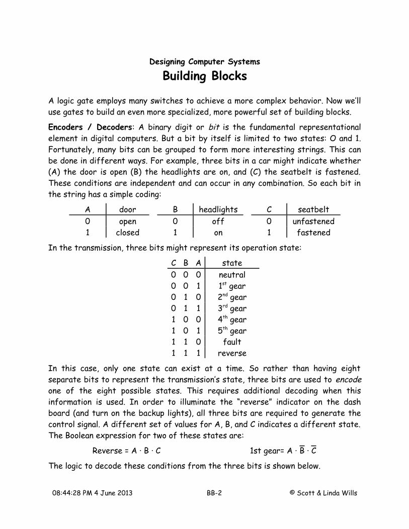
BCD to 7 Segment Decoder: Not all decoders assert one of M outputs. Sometimes the decoded outputs have a different requirement. For example, many numerical displays use a seven segment display to show a decimal digit. The digits are labeled a, b, c, d, e, f, and g. Any decimal digit (0-9) can be created by turning on different combination of these named segments. A four bit binary coded decimal (BCD) can be used as input to a decoder than switches on the proper segments for the corresponding digit character. When enable is low, all segments are switched off, blanking the display.
08:44:30 PM 4 June 2013 BB-4 © Scott & Linda Wills
a
b
c
d
e
f
g
I3 I2 I1 I0 En Oa Ob Oc Od Oe Of Og
X X X X 0 0 0 0 0 0 0 00 0 0 0 1 1 1 1 1 1 1 00 0 0 1 1 0 1 1 0 0 0 00 0 1 0 1 1 1 0 1 1 0 10 0 1 1 1 1 1 1 1 0 0 10 1 0 0 1 0 1 1 0 0 1 10 1 0 1 1 1 0 1 1 0 1 10 1 1 0 1 1 0 1 1 1 1 10 1 1 1 1 1 1 1 0 0 0 01 0 0 0 1 1 1 1 1 1 1 11 0 0 1 1 1 1 1 0 0 1 1
Here multiple outputs are asserted for each code. But the gate implementation is still direct. Each of the seven outputs can be expressed and simplified as a function of the four bit binary number and enable.
Decoders extract the coded information in a binary string to assert one or more outputs. They are a widely used building block. But how do we get the encoded word in the first place? Perhaps by using an encoder !
Encoders: If the job of decoders is to turn an N-bit coded binary string into M uncoded outputs, then an encoder must perform the reverse process: turning an asserted input into a coded binary string (a N-bit binary number). This is more complicated than is sounds.
08:44:30 PM 4 June 2013 BB-5 © Scott & Linda Wills

O0
O1
On-1
...
N-bitbinarynumber
M t
o N
enco
der
...
I1I0
I2I3I4I5I6
Im
I7
M binaryinputs
Consider the behavior of a 2 to 4 encoder.
I0 I1 I2 I3 O1 O0
1 0 0
1 0 1
1 1 0
1 1 1
O0
O1
4 to
2en
code
r I1
I0
I2
I3
When a single input is asserted, the output string corresponds to the number of the asserted input. For example, when I2 is asserted, the output string is “10” which represents a binary “2”. An ambiguity occurs when no inputs are asserted. What should the output be. Since all 2N output values already have a defined meaning (i.e., the number of the asserted input), what remains to indicate no asserted inputs? Its time to add a new output: Valid.
I0 I1 I2 I3 V O1 O0
0 0 0 0 0 X X
1 1 0 0
1 1 0 1
1 1 1 0
1 1 1 1
O0
O1
4 to
2en
code
r I1
I0
I2
I3Valid
The valid output (V) indicates that an input is asserted and an valid encoded output is available. If no inputs are asserted, the valid signal is low and the outputs are
08:44:30 PM 4 June 2013 BB-6 © Scott & Linda Wills

undefined. When using an encoder, the outputs should only be sampled when V is high. If V is low, no inputs are asserted to encode.
What's your priority?: But what happens when more than one input is asserted? In this case, the inputs require a priority scheme so that the highest priority input is encoded into a binary output value. Input priority can be used to expand the five case behavior table (show above) into the full 16 cases that can occur. That assume a simple priority scheme:
I3 > I2 > I1 > I0
Under this scheme, if I3 is asserted, the state of the other inputs is of no concern. I3 will be encoded as output 11. If I3 is zero, but I2 is asserted, the output will reflect this encoding: 10. If I1 is the asserted value being encoded (because I3 and I2 are zero), the output becomes 01. Finally, if only I0 is asserted, the output value is 00.
I0 I1 I2 I3 V O1 O0
0 0 0 0 0 X X
1 0 0 0 1 0 0
X 1 0 0 1 0 1
X X 1 0 1 1 0
X X X 1 1 1 1
This leads to a implementation by simplifying the output behaviors as Boolean expression. Normally Karnaugh Maps are needed. But this behavior has obvious expressions.
V=I0 I1 I2 I3
O1=I3 I2
O0= I3I1⋅I2
If the input priorities are changed, the Xs and 0s can be easily changed to reflect the new behavior. The rows are processed in a different order. But the same process is applied. In order for a given row to represent the encoded input, all higher priority inputs must be 0 while all lower priority inputs are ignored (don't cared). Here's another example.
08:44:30 PM 4 June 2013 BB-7 © Scott & Linda Wills

I1 > I3 > I0 > I2
I0 I1 I2 I3 V O1 O0
0 0 0 0 0 X X
1 0 X 0 1 0 0
X 1 X X 1 0 1
0 0 1 0 1 1 0
X 0 X 1 1 1 1
Summary: In general, decoders and encoders transform N-bit binary numbers into assertions of one of M outputs, and back. They change the how the value is represented.
Steering Logic: Sometimes the goal is not to transform data but rather to move it from one place to another. Wire, optical, and wireless channels do a good job of transporting data. But sometimes logic is required to steer data into and out of these channels. For example, we might want to connect multiple sensors that collect information to multiple controllers that process the data. Rather than connecting dedicated wires between each sensor and controller, we can multiplex the data (in time) on a single wire.
S
S
S
S
C
C
C
C
S
S
S
S
C
C
C
CI0
I1
I2
I3
S1 S0
O0
O1
O2
O3
S1 S0
two bitbinaryselect
two bitbinaryselect
There are many uses for a digital block that can steer one of many inputs into an output (a multiplexer). Steering a single input to one on many outputs (a demultplexer) is also valuable. Let's explore their design.
08:44:30 PM 4 June 2013 BB-8 © Scott & Linda Wills
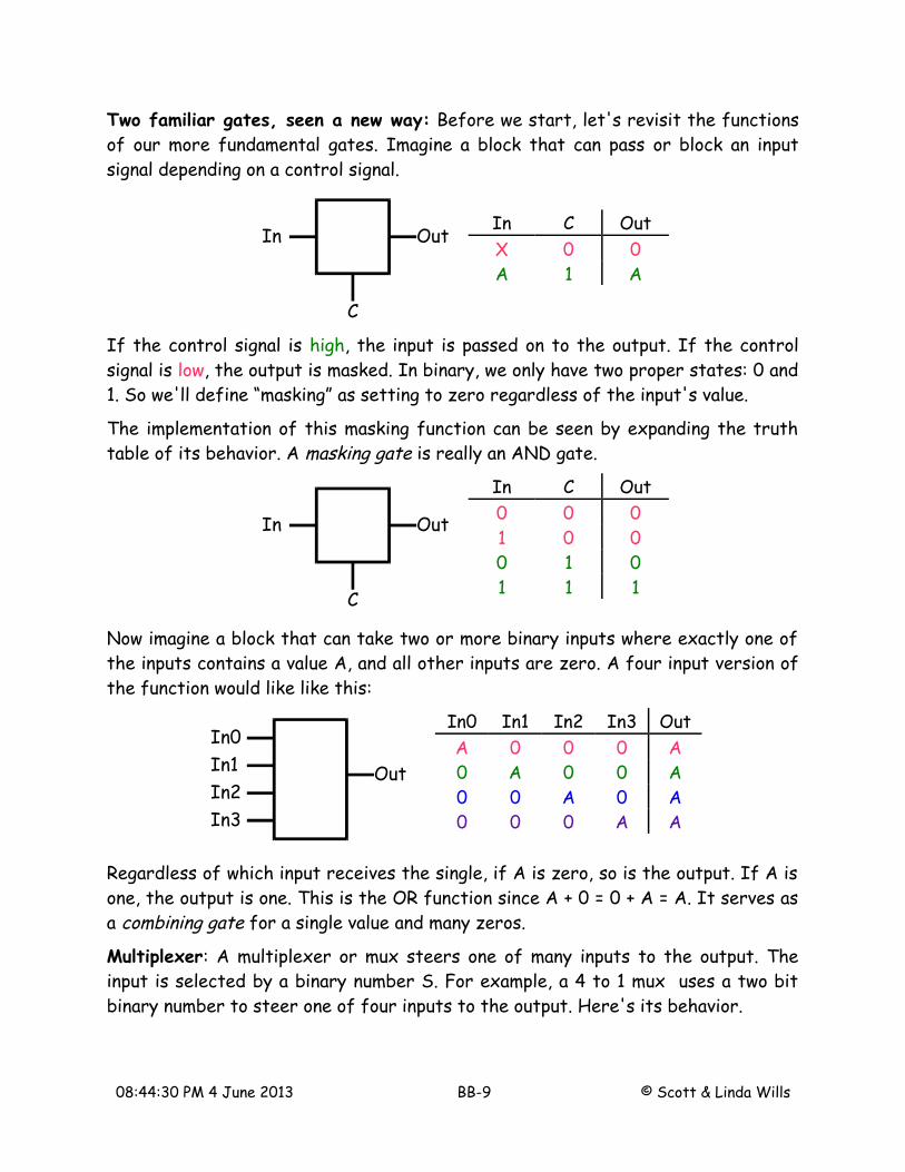
Two familiar gates, seen a new way: Before we start, let's revisit the functions of our more fundamental gates. Imagine a block that can pass or block an input signal depending on a control signal.
In Out
C
In C OutX 0 0A 1 A
If the control signal is high, the input is passed on to the output. If the control signal is low, the output is masked. In binary, we only have two proper states: 0 and 1. So we'll define “masking” as setting to zero regardless of the input's value.
The implementation of this masking function can be seen by expanding the truth table of its behavior. A masking gate is really an AND gate.
In Out
C
In C Out0 0 01 0 00 1 01 1 1
Now imagine a block that can take two or more binary inputs where exactly one of the inputs contains a value A, and all other inputs are zero. A four input version of the function would like like this:
In0
OutIn1In2In3
In0 In1 In2 In3 OutA 0 0 0 A0 A 0 0 A0 0 A 0 A0 0 0 A A
Regardless of which input receives the single, if A is zero, so is the output. If A is one, the output is one. This is the OR function since A + 0 = 0 + A = A. It serves as a combining gate for a single value and many zeros.
Multiplexer: A multiplexer or mux steers one of many inputs to the output. The input is selected by a binary number S. For example, a 4 to 1 mux uses a two bit binary number to steer one of four inputs to the output. Here's its behavior.
08:44:30 PM 4 June 2013 BB-9 © Scott & Linda Wills

In0
OutIn1In2In3
S1 S0
4 to 1Mux
In0 In1 In2 In3 S1 S0 OutA B C D 0 0 AA B C D 0 1 BA B C D 1 0 CA B C D 1 1 D
Note that the binary number represented by S1 and S0 controls which input value is passed through to the output. The behavior can be realized using a 2 to 4 decoder and the masking and combining gates described above.
In0
Out
In1
In2
In3
S1 S0
2 to 4Decoder En
O0 O1 O2 O3
Each input is connected to a masking (AND) gate controlled by the corresponding decoder output. So only the input decoded from the binary input S will be passed through to the combining (OR) gate. All other inputs will be masked to zero. The combining gate ignores zeros, outputting the one passed input.
This behavior can also be expressed as Boolean expressions.
Out= In0⋅S 1⋅S 0In1⋅S 1⋅S 0 In2⋅S 1⋅S 0In3⋅S 1⋅S 0
It can be implemented using AND and OR gates as shown below. Note that the four input OR gate can be broken into a combination of two input ORs.
08:44:30 PM 4 June 2013 BB-10 © Scott & Linda Wills

Here S1 and S0 contain the value 01 (shown on the left). I1's high value (red) is passed forward while all other masking gates are blocking inputs. The combining OR gates then pass this value forward to the output. If S is changed to the value 11, I3 becomes the signal that is steered to the output (shown on the right).
If the selected input happened to have a low value (I2, shown as blue on left), the output would be zero. However if I2 changes to a high value, this change is also be seen at the output (shown on right).
To reduce implementation cost, these AND and OR gates can be transformed to NAND gates using mixed logic. If three and four input gates are available (they are in VLSI), the implementation can be reduced to four 3-input NAND, one 4-input NAND, and two inverters for a total of 24 + 8 + 4 = 26 transistors. because of the inversions, this implementation is less easy to follow an input to the output. But it still works!
08:44:31 PM 4 June 2013 BB-11 © Scott & Linda Wills

Demultiplexer: So what is the device that performs the reverse operation. A demultiplexer or demux takes a single input and, under control of a binary number, steers it to one of many outputs. The fundamental operation is easy to understand.
Out0
In Out1Out2Out3
S1 S0
1 to 4Demux
In S1 S0 O0 O1 O2 O3A 0 0 AA 0 1 AA 1 0 AA 1 1 A
However deciding the status of unselected outputs (off-diagonal values) dramatically affects the implementation and use of a demux. Suppose unselected outputs are don't cared. After all, they're not selected. In this case, the implementation can be extremely inexpensive!
In S1 S0 O0 O1 O2 O3A 0 0 A X X XA 0 1 X A X XA 1 0 X X A XA 1 1 X X X A
This is fanout. It is cheap and useful. Fanout is simply taking a value (in CMOS, a value is a high or low voltage), and connecting it to multiple inputs. Since using an input, or ignoring it does not affect the value, there is no obstacle to fanout (aside from parasitic loading that affects the wire's speed). But it marginally deserves the title “demux”.
08:44:32 PM 4 June 2013 BB-12 © Scott & Linda Wills
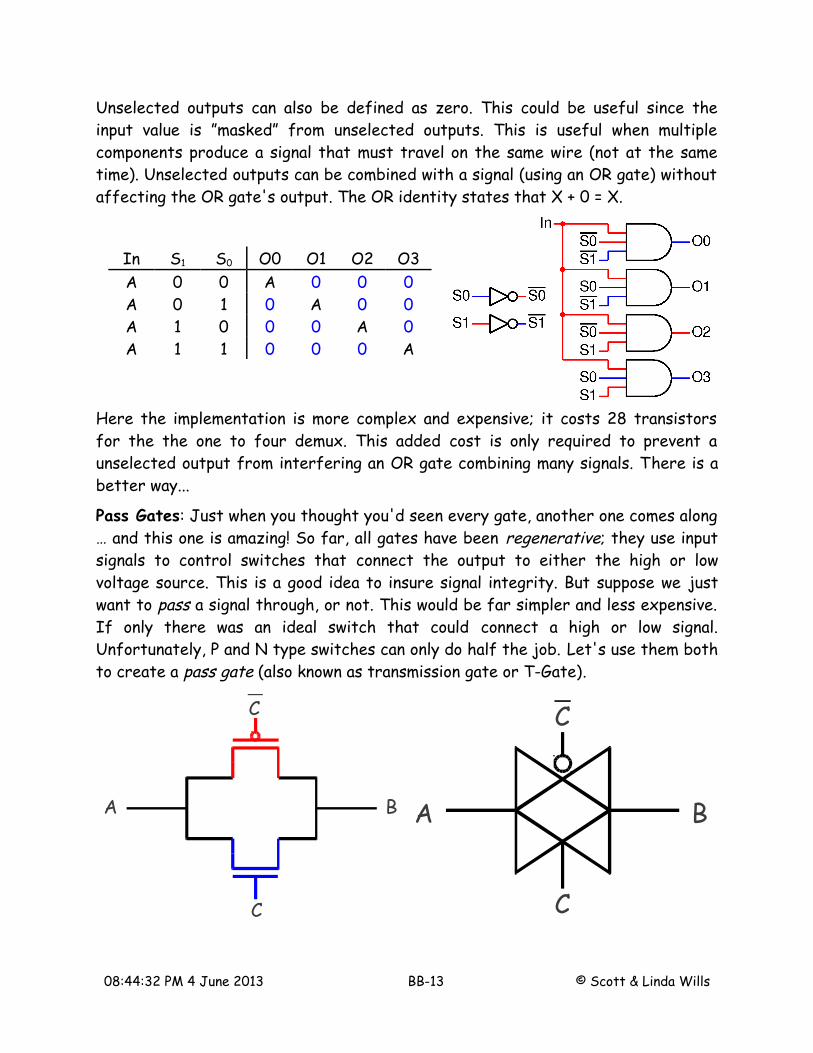
Unselected outputs can also be defined as zero. This could be useful since the input value is ”masked” from unselected outputs. This is useful when multiple components produce a signal that must travel on the same wire (not at the same time). Unselected outputs can be combined with a signal (using an OR gate) without affecting the OR gate's output. The OR identity states that X + 0 = X.
In S1 S0 O0 O1 O2 O3A 0 0 A 0 0 0A 0 1 0 A 0 0A 1 0 0 0 A 0A 1 1 0 0 0 A
Here the implementation is more complex and expensive; it costs 28 transistors for the the one to four demux. This added cost is only required to prevent a unselected output from interfering an OR gate combining many signals. There is a better way...
Pass Gates: Just when you thought you'd seen every gate, another one comes along … and this one is amazing! So far, all gates have been regenerative; they use input signals to control switches that connect the output to either the high or low voltage source. This is a good idea to insure signal integrity. But suppose we just want to pass a signal through, or not. This would be far simpler and less expensive. If only there was an ideal switch that could connect a high or low signal. Unfortunately, P and N type switches can only do half the job. Let's use them both to create a pass gate (also known as transmission gate or T-Gate).
A B
C
C
A B
C
C
08:44:32 PM 4 June 2013 BB-13 © Scott & Linda Wills

Two switches are connected at their switch points (source and drain) and opened or closed together. With this construction, a P-type switch is available to pull high while a N-type can pull low. With both switches closed, the signal level at A can be high or low and the most capable switch is there to connect the signal to B. Sometimes folks think that only one switch needs to be closed, depending on the signal being passed. But by closing both switches together, it really doesn't matter if the signal is high, low, or changing back ands forth!
Interestingly, this switch really doesn't have an input and an output. Instead it has two terminals (A and B) that can be connected together when the control signal C is high. When C is low, the terminals A and B are isolated. This component acts as an “ideal switch” and its extremely useful. It's gate icon looks like two overlapping buffers showing how signals can be passed bidirectionally. The control signals C and C arrive that mid point of the two buffers. The bubble indicates the active low control. Look carefully at the pass gate and its icon show side by side above. The icon is on the left; the implementation (using one P-type switch and one N-type switch) is on the right.
A Demux Using Pass Gates: We can use a couple of pass gates to create a demux with a twist.
In S O0 O1A 0 A Z0
A 1 Z0 A
Here the input value is passed to the selected output via a closed pass gate. The cyan bar on the pass gate indicates the gate is closed; it is not part of the icon. This output is like our previous demux implementations. However the unselected output isn't zero, it isn't connected to anything, Its floating. This condition is indicated in the truth table with the somewhat cryptic symbol Z0 which means high impedance. But this is just a fancy way to say “floating”. Because its floating, it can be connected to another signal with no risk of contention (and no OR gate required). If we want more outputs on our demux, we can replicate this demux in a binary tree.
08:44:32 PM 4 June 2013 BB-14 © Scott & Linda Wills

In S1 S0 O0 O1 O2 O3A 0 0 A Z0 Z0 Z0
A 0 1 Z0 A Z0 Z0
A 1 0 Z0 Z0 A Z0
A 1 1 Z0 Z0 Z0 A
Here S1 is low so the input travels through the top pass gate. Since S0 is high, the bottom pass gate of each 2 to 1 demux is closed. But only the uppermost 2 to 1 demux has an input to connect to the output. So all but the selected output, O1, have floating outputs. O1 will follow In.
The function of this implementation is similar to the gate implementation. However, this version has floating unselected outputs (a good thing) and a lower implementation cost: 16 versus 28 switches (an even better thing).
A Mux Using Pass Gates: What's good for demuxes is also good for muxes. Here's a 2 to 1 and a 4 to 1 implemented using pass gates.
These muxes also enjoys a low implementation cost (6 and 16 switches respectively) and they behave exactly as the gate version. These implementations employ binary
08:44:33 PM 4 June 2013 BB-15 © Scott & Linda Wills
tree construction. To double the number of inputs, just replicate the current mux and then add one more on the end. An 8 to 1 mux would stack two 4 to 1 muxes and then add an extra 2 to 1 mux (controlled by S2) to choose between their outputs. Using pass gates, muxes are as easy to build as demuxes … hey wait a minute.
Mirror Twins: Regarding the switch contacts, pass gates don't have inputs and outputs like other gates. Either terminal can pull the other. So muxes and demuxs built as binary trees of pass gates are the same thing, but for switching inputs and outputs. In fact they are mirror images of each other.
Summary: Building blocks provide a new abstraction for digital design. What decoders and muxes loss in the generality of gates, they gain in functionality. Its important to remember that, while they have similar appearances, they accomplish different objectives.
• Decoders and encoders perform translation between binary numbers and less compact, but valuable presentations (e.g., selecting one of eight outputs to be high).
• Muxes and demuxes are all about steering signals in and out of shared channels. They can also select a value, or help multiple components share a communications medium. They are controlled by a binary value. But they still just connect an input to an output.
• Pass gates are the ideal switch we wish we had all along. It can pull high and low. But it requires a control signal and its complement. It connect to wires. Or it can leave then floating. An most amazingly, it provide bidirectional connections for flexibility not achieved with other gates.
08:44:33 PM 4 June 2013 BB-16 © Scott & Linda Wills