Embed Size (px)
DESCRIPTION
Building design
Citation preview

Designing Buildings to Resist Explosive
Threats
by Robert Smilowitz
Weidlinger Associates, Inc.
Last updated: 10-19-2011
Within This Page
Introduction
Description
Relevant Codes and Standards
Additional Resources
Introduction
The four basic physical protection strategies for buildings to resist explosive threats are
1) Establishing a secure perimeter; 2) Mitigating debris hazards resulting from the
damaged façade (see also WBDG Glazing Hazard Mitigation; 3) Preventing progressive
collapse; and 4) Isolating internal threats from occupied spaces. Other considerations,
such as the tethering of non-structural components and the protection of emergency
services, are also key design objectives that require special attention.
Generally, the size of the explosive threat will determine the effectiveness of each of
these protective strategies and the extent of resources needed to protect the occupants.
Therefore, determining the appropriate design threat is fundamental to the design process
and requires careful consideration.
Back to top
Description
A. Defining the Design Threat
Comprehensive threat and vulnerability assessments, and risk analysis can help the
design team understand the potential threats, vulnerabilities, and risks associated with a
building as well as determine the design threat for which a building should be designed to
resist. Usually, the definition of the design threat is based on history and expectation.
However, it is limited by the size of the means of delivery. For example, a hand-carried
device, if efficiently packaged, could occupy as little as half a cubic foot of space and
could be easily concealed in a large brief case or small luggage and introduced deep into
the structure where it could do considerable damage. As a result, screening stations at the

entrances, mailrooms, and loading docks provide the best means of preventing hand-
carried satchel threats from entering the occupied spaces. On the other hand, vehicle
threat, which can carry significantly larger explosive charge weights, requires secured
perimeters and comprehensive screening procedures for underground parking structures
or loading docks.
Screening procedures, however, have limitations and the potential for threats to bypass
their scrutiny must be recognized in the physical protection scheme. Therefore, the
selection of the design level explosive threat depends on the features of the building, the
site conditions, and the level of risk the client is prepared to accept.
Blast Loading
Because this Resource Page focuses on explosive threat, one must first understand how a
blast affects its surrounding environment. When an explosive device is detonated at or
near the ground surface, shock waves radiate hemispherically and the peak intensity blast
pressure decays as a function of the distance from the source. The incident peak pressures
are amplified by a reflection factor as the shock wave encounters an object or structure in
its path. Reflection factors depend on the intensity of the shock wave and the angle of
obliquity of the shock front. However, when the explosion is within an occupied space,
the confinement of the explosive by-products produces a quasi-static gas pressure that
needs to be vented into the atmosphere.
The intensity of the blast pressures is therefore a function of the charge weight and the
standoff distance to the protected space. Charges situated extremely close to a target
structure impose a highly impulse, high intensity pressure load over a localized region of
the structure. This high intensity loading tends to shatter or shear through the structural
materials. At greater distances, the intensity of the peak pressure is significantly reduced;
however, the surface area over which it acts is much greater. As a result, the hazard
potential is increased over a larger portion of the structure.
Dynamic Analysis of Building Systems
The performance of building systems in response to explosive loading is highly dynamic,
highly inelastic, and highly interactive. By controlling the flexibility and resulting
deformations, structural or façade components may be designed to dissipate considerable
amounts of blast energy. The phasing of the different responses and the energy that is
dissipated through inelastic deformation must be carefully represented in order to
accurately determine the behavior. The 'sequential single-degree-of freedom (SDOF)
model' approach, commonly used to analyze individual components, is likely to produce
overly conservative designs, while an accurate representation of the structural system
truly requires a complex 'multi-degree-of-freedom (MDOF) model.' These MDOF
models may be developed using appropriate inelastic Finite Element software for which
an explicit formulation of the equations of motion may be solved. The details of the finite
element models, including the interaction between the glass and the support mullions,
will determine the accuracy of the analysis. Only this approach will provide the most
authentic representation of the system's ability to resist the dynamic blast loading AND
provide the most economical design.
Performance Standards
Analytical tools that evaluate the likely performance of curtain-wall façades in response
to blast loads are used to demonstrate compliance with established blast criteria or
performance specifications. Many of these performance specifications contain the
criterion that the building system must be a balanced design. The objective of this
criterion is to realize the capacity of all the materials, maximize the potential energy
dissipated due to deformation, and manage the failure mechanisms. This is accomplished
by assuring a controlled sequence of failure. Depending on the specified performance
conditions, the application of this criterion could have significant impact on the sizing of
the members and the design of the connections between the different components.
The behavior of structural materials, such as steel and aluminum, in response to explosive
loading was the subject of intense investigation by the governments of the United
Kingdom, Israel, and the United States of America. Some of these materials behave very
differently when subjected to high strain rate loading than they do under static conditions.
Furthermore, the inelastic deformation of these members depends on their section
properties, shape functions, and extent of deformation. For compound sections composed
of different pieces and materials, transformed section properties may be used to
characterize an equivalent material and a combined or composite section property may be
used to represent its structural resistance. Care must be taken to calculate composite
section properties when strain compatibility between components can be justified and
combined section properties when deformation compatibility between components is
enforced.
B. Physical Protection Strategies and Features
Perimeter Protection
While it may be possible to predict effects of a certain charge weight at a specified
standoff distance, the actual charge weight of the explosive used by a terrorist, the
efficiency of the chemical reaction, and the source location cannot be reliably predicted.
Given the uncertainties, the most effective means of protecting a structure is to keep the
explosive as far away as possible by maximizing the keep-out or standoff distance.
However, this approach is only necessary if an analysis identifies the building to be at
risk of attack as opposed to suffering collateral damage due to an attack on a nearby
target.
To guarantee the maximum keep-out distance between unscreened vehicles and the
structure, anti-ram bollards or large planters must be placed at the curb around the
perimeter of the building. The site conditions will determine the maximum speeds
attainable, and thus the kinetic energy that must be resisted. Both the bollard and its
foundation must be designed to resist the maximum load. Conversely, if design

restrictions limit the capacity of the bollard or its foundation, then site restrictions will be
required to limit the maximum speed attainable. Furthermore, public parking abutting the
building must be secured or eliminated, and street parking should not be permitted
adjacent to the building. Removing one lane of traffic and turning it into an extended
sidewalk or plaza can gain additional standoff distance. However, the practical benefit of
increasing the standoff depends on the charge weight. If the charge weight is small, this
measure will significantly reduce the forces to a more manageable level. If the threat is a
large charge weight, the blast forces may overwhelm the structure despite the addition of
nine or ten feet to the standoff distance and the measure may not significantly improve
survivability of the occupants or the structure.
Façade Protection
The building's exterior is its first real defense against the effects of a bomb. How the
façade responds to this loading will significantly affect the behavior of the structure.
Hardening of the façade is typically the single most costly and controversial component
of blast protection, and may produce a dramatic change to the exterior appearance of the
structure such as smaller window sizes and more rugged attachments. Moreover, given
the large surface areas of most buildings, modest levels of protection may not be cost-
effective. Therefore, it may be best to concentrate on improving the post-damaged
behavior of the façade.
Except for very thick lights, most glazing materials and components designed to respond
to the blast loads will most likely be damaged by the blast overpressures. To improve the
post-damage behavior of the glazing system, one could specify laminated glass for new
construction or apply anti-shatter film to existing glazing. While these features do little to
improve the strength of the glass, they attempt to hold the shards of glass together and
better protect the occupants from hazardous debris (see also WBDG Glazing Hazard
Mitigation. Laminated glass possesses the best post-damage behavior, may be used with a
wide variety of glazing materials and thickness, and provides the highest degree of safety
to occupants. The effectiveness of Mylar films, on the other hand, depends on the method
of application and the thickness of the film. Common film systems range from a simple
edge-to-edge (daylight) application, to a wet glazed adhesion, to a mechanical attachment
to the existing window frame. The mechanical attachments are most effective when they
are anchored to the underlying structure. Regardless of the method, there are architectural
issues and life-cycle costs associated with the use of anti-shatter films.
Equally important to the design of the glass is the design of the window frames. For the
window to properly fail, the glass must be held in place long enough to fail. Short of that,
the glazing will dislodge from the housing intact and cause serious damage or injury. The
capacity of the frame system to resist blast loading should therefore exceed the
corresponding capacity of the glazing, often referred to as the "glass fail first criteria."
Factors of two to three, over the nominal capacity of the glass to resist breakage, may be
required to design the frames. The bite, including the possible use of structural silicone
sealant, must be adequate to assure the failed glass is retained within the frame.
Depending on the façade, the mullions may be designed to span from floor to floor or tie

into wall panels and must be capable of withstanding the reactions of a window loaded to
failure. Finally, the walls to which the windows are attached must be designed to accept
the reaction forces as well.
Designing glazing systems capable of resisting a specified overpressure requires a
cascade of costly upgrades to the façade, including really thick laminated glass, and
relatively heavy frames and mullions. There are also major construction challenges such
as reinforcement and steel embedments that get in the way of new cast-in-place
reinforced concrete wall construction, and the substantial anchorage required to
accommodate the large reaction forces. Moreover, attaching these window systems to
existing walls may even be a physical impossibility. Because the improved capacity is
likely to fall far short of the pressures associated with a realistic terrorist threat, it is
recommended that for new construction with low threat criteria and limited budgets for
blast protection, the engineer select the weakest laminated glazing that satisfies wind and
serviceability requirements. In this way, the improved post failure behavior provides the
occupants a measure of protection at a reasonable cost.
Curtain Wall Protection
Fig. 1. Sample blast curtain wall engineered to take advantage of a flexible system. Some
protective features may include: insulated glazing unit with laminated inner light; glazing
adhered to mullion with structural silicone sealant; and curtain-wall frame with steel
backup encased in aluminum.
A curtain wall is a nonbearing exterior enclosure that is supported by a building's
structural steel or concrete frame and holds either glass, metal, stone, or precast concrete
panels. Lightweight and composed of relatively slender extruded aluminum members,
curtain-wall façades are considerably more flexible than conventional, hardened punched
window systems. In a blast environment, the mullion support would absorb a portion of
the blast energy and improve the performance of the glazing, allowing the glazing to
sustain greater blast environments (although the mullions themselves should be designed
to resist the forces collected by the glass).
It is important to take into account the inherent flexibility of curtain-wall systems when
sizing members for blast loads and evaluating the glazing for hazard. This enables the

engineer to both ascertain the true blast worthiness of the curtain wall as well as to
properly calculate the reduced load transfer into supporting structural elements.
The design of curtain-wall systems to withstand the effects of explosive loading depends
on the performance of the various elements that comprise the system. Curtain-wall
response software, based on more sophisticated finite element methods than simplified
Single-Degree-of-Freedom glass fragment hazard analytical approaches, was developed
for the Department of Defense, Technical Support Working Group (TSWG) to accurately
represent the capacity of the glazing and the supporting frame members. While the
glazing may be the most brittle component, the performance of the system, and the
reduction of hazard to the occupants depend on the interaction between the capacities of
the various elements. In addition to hardening the individual members that comprise the
curtain-wall system, the attachments to the floor slabs or spandrel beams require special
attention. These connections must be adjustable to compensate for the fabrication
tolerances and accommodate the differential inter-story drifts and thermal deformations
as well as be designed to transfer gravity loads, wind loads, and blast loads.
Energy-Absorbing Catch Systems
Fig. 2. Sample catch system
An alternative approach to blast protection takes the concept of a flexible curtain-wall
system one step further by making full use of the flexibility and capacity of all the
window materials to absorb and dissipate large amounts of blast energy while preventing
debris from entering the occupied space. Energy-absorbing catch systems (a.k.a. Cable
Protected Window Systems (CPWS)) work in such a way that as the glass is damaged it
bears against a cable catch system, which in turn deforms the window frames. Extensive
explosive testing, as well as sophisticated computer simulations, has demonstrated the
effectiveness of these systems.
Floor Slab Reinforcements
A reinforced-concrete, flat-plate structural slab is an economical system that provides for
maximum use of vertical space, particularly for buildings in areas with height restriction.
However, when subjected to a blast load, punching shear and softening of the moment-
resisting capacity of the slabs will reduce the lateral-load-resisting capacity of the system.

Once the moment-resisting capacity of the slabs at the columns is lost, the ability of the
slab to transfer forces to the shear walls is diminished and the structure is severely
weakened. In addition to the failure of the floor slab, the loss of contact between the slab
and the columns may increase the unsupported column lengths, which may lead to the
buckling of those columns. Furthermore, the lateral load resisting system—which
consists of the shear walls, the columns, and the slab diaphragms that transfer the lateral
loads—may be weakened to such an extent that the whole building may become laterally
unstable.
Fig. 3. Floor slabs
Conventional flat-plate design may be upgraded by paying more attention to the design
and detailing of exterior bays and lower floors, which are the most susceptible to an
exterior vehicle explosive threat, and the design of the spandrel beams, which tie the
structure together and enhance the response of the slab edge. Drop panels and column
capitols may be used to shorten the effective slab length and improve the punching shear
resistance. If vertical clearance is a problem, shear-heads embedded in the slab will
improve the shear resistance and improve the ability of the slab to transfer moments to
the columns. Furthermore, the blast pressures that enter the structure through shattered
windows and failed curtain walls will load the underside and subsequently the top
surfaces of the floor slabs along the height of the building. Both the delay in the sequence
of loading and the difference in magnitude of loading will determine the net pressures
acting on the slabs. Consequently, there will be a brief time in which each floor will
receive a net upward loading. This upward load requires that the slab be reinforced to
resist loads opposing the effects of gravity.
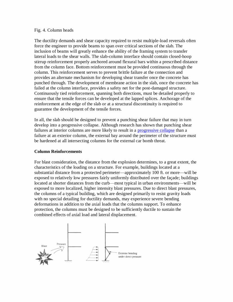
Fig. 4. Column heads
The ductility demands and shear capacity required to resist multiple-load reversals often
force the engineer to provide beams to span over critical sections of the slab. The
inclusion of beams will greatly enhance the ability of the framing system to transfer
lateral loads to the shear walls. The slab-column interface should contain closed-hoop
stirrup reinforcement properly anchored around flexural bars within a prescribed distance
from the column face. Bottom reinforcement must be provided continuous through the
column. This reinforcement serves to prevent brittle failure at the connection and
provides an alternate mechanism for developing shear transfer once the concrete has
punched through. The development of membrane action in the slab, once the concrete has
failed at the column interface, provides a safety net for the post-damaged structure.
Continuously tied reinforcement, spanning both directions, must be detailed properly to
ensure that the tensile forces can be developed at the lapped splices. Anchorage of the
reinforcement at the edge of the slab or at a structural discontinuity is required to
guarantee the development of the tensile forces.
In all, the slab should be designed to prevent a punching shear failure that may in turn
develop into a progressive collapse. Although research has shown that punching shear
failures at interior columns are more likely to result in a progressive collapse than a
failure at an exterior column, the external bay around the perimeter of the structure must
be hardened at all intersecting columns for the external car bomb threat.
Column Reinforcements
For blast consideration, the distance from the explosion determines, to a great extent, the
characteristics of the loading on a structure. For example, buildings located at a
substantial distance from a protected perimeter—approximately 100 ft. or more—will be
exposed to relatively low pressures fairly uniformly distributed over the façade; buildings
located at shorter distances from the curb—most typical in urban environments—will be
exposed to more localized, higher intensity blast pressures. Due to direct blast pressures,
the columns of a typical building, which are designed primarily to resist gravity loads
with no special detailing for ductility demands, may experience severe bending
deformations in addition to the axial loads that the columns support. To enhance
protection, the columns must be designed to be sufficiently ductile to sustain the
combined effects of axial load and lateral displacement.

Fig. 5. Direct pressure
In conditions that cause uplift—the net upward load on the slab—the column's tension
will experience a brief tensile force. Conventional reinforced concrete columns not
designed to resist the combined effects of bending may be prone to damage under these
conditions. The lower-floor columns must therefore be designed with adequate ductility
and strength to resist the effects of direct lateral loading from the blast pressure and
impact of explosive debris. Reinforced concrete columns may be designed to resist the
effects of an explosion by providing adequate longitudinal reinforcement, staggering the
bar splices, and providing closely spaced ties at plastic hinge locations. Steel columns
may be sized to withstand the lateral loads and column splices may be detailed to develop
the plastic moments of the section. Existing concrete columns may be encased in a steel
jacket or wrapped with a composite fiber to confine the concrete core and increase the
shear capacity. On the other hand, existing steel columns may be encased in concrete to
add mass and prevent a premature buckling of the thin flanges. For more information on
retrofitting existing buildings, see WBDG Retrofitting Existing Buildings to Resist
Explosive Threats.
Fig. 6. Uplift
Fig. 7. Weakened connection
Preventing Progressive Collapse
In addition to façade debris hazards, building occupants may be vulnerable to heavier
debris resulting from structural damage. Progressive collapse occurs when an initiating
localized failure causes adjoining members to be overloaded and fail, resulting in an
extent of damage that is disproportionate to the originating region of localized failure. A

protective design may avoid structural systems that either facilitate or are vulnerable to a
progression of collapse resulting from the loss of a primary vertical load-bearing
member.
New facilities may be designed to accept the loss of an exterior column for one or
possibly two floors above grade without precipitating further collapse. In these cases, the
design requirements are intended to be threat-independent to protect against an explosion
of indeterminate size that might damage a single column, which results in adequate
redundant load paths in the structure should damage occur due to an unspecified
abnormal loading. The upgrade of existing structures to prevent localized damage from
developing into a progressive collapse may not be easily accomplished through the
alternate path method. This is because the loss of support at a column line would increase
the spans of all beams directly above the zone of damage and require different patterns of
reinforcement and different types of connection details than those typically detailed for
conventional structural design. For more information on retrofitting existing buildings,
see WBDG Retrofitting Existing Buildings to Resist Explosive Threats.
Alternatively, columns may be sized, reinforced, or protected to prevent critical damage
as a result of the design threat charge weight that may be located in close proximity to
them. The vulnerable concrete columns may be jacketed with steel plate or wrapped with
composite materials and the vulnerable steel columns may be encased in concrete to
protect the cross sections and add mass. For the upgrade of existing structures, these
approaches are better for preventing progressive collapse than supplementing the capacity
of the connecting beams and girders, or upgrading them using the alternate path method.
However, the effectiveness of these approaches is predicated on the operational and
technical security procedures that will limit the magnitude of the explosive threat. This
includes the establishment of effective perimeter protection, adequate screening of
vehicles entering an underground parking facility or loading dock, and inspection of
parcels that may be hand carried into the building. For more information on retrofitting
existing buildings, see WBDG Retrofitting Existing Buildings to Resist Explosive
Threats.
Fig. 8. Catenary
Transfer Girder Reinforcements

Transfer girders and the columns supporting transfer girders are particularly vulnerable to
blast loading. Transfer girders typically concentrate the load-bearing system into a fewer
number of structural elements, which contradicts the concept of redundancy desired in a
blast environment. Typically, the transfer girder spans a large opening, such as a loading
dock, or provides the means to shift the location of column lines at a particular floor.
Damage to the girder may leave several lines of columns, which terminate at the girder
from above, totally unsupported. Similarly, the loss of a support column from below will
create a much larger span that bears critical loads. Transfer girders, therefore, create
critical sections the loss of which may result in a progressive collapse. So if a transfer
girder is required and vulnerable to an explosive loading, then the girder should be
designed to be continuous over several supports. There should be substantial structure
framing into the transfer girder to create a two-way redundancy, thereby an alternate load
path in the event of a failure. The column connections, which support the transfer girders,
should be designed as Type 2 connections to provide sustained strength despite inelastic
deformations.
Fig. 9. Transfer girders
Overall Lateral Resistance
The conventional lateral loads—wind and seismic zone 1 forces—to which most
buildings are designed are minimal. These minimal lateral load requirements may be
resisted by a combination of shear walls, braced frames, and moment-resisting frame
action. At each floor level, the slab diaphragms transfer the lateral loads to the lateral-
load resisting system. Each component of the lateral-load resisting system must be
checked to determine its adequacy to resist blast loads. Depending on the results of a
blast analysis, the individual elements of the lateral-load resisting system may require
modification.
Buildings with an irregular floor plan will induce large torsional effects on the lateral-
load resisting system. Typically, symmetrical buildings behave better when subjected to
blast or seismic loading. If the shear core is centrally loaded a large demand is placed on
the diaphragm action of the floor slab to transmit the lateral loads from the perimeter of
the floor into the central shear walls. This effect can be more critical for blast load than
for seismic load. Seismic base motions are typically applied over the entire foundation;
blast loads resulting from a close-in explosion tend to impose higher intensity loads over

a more concentrated region. Although the total base shears may be nominally the same,
the lateral-resisting behavior is not. The usual rigid diaphragm action might not be
suitable in such a localized blast situation and a full three-dimensional analysis of the
building might be required.
Fig. 10. Diaphragm action
The ability of structures to resist a highly impulsive blast loading depends in great
measure on the structural detailing of the slabs, joists, and columns that provides for the
ductility of the load-resisting system. The structure has to be able to deform inelastically
under extreme overload (i.e., dissipate large amounts of energy) prior to failure.
Provisions have been established for the design of structures to resist seismic forces that
ensure both the ductility of the members and the capacity of the connections to undergo
large rotations without failing. For example, the provisions of Chapter 21 of the
American Concrete Institute 318 were devised to improve the behavior of reinforced
concrete structures subjected to large inelastic deformations.
In addition to providing ductile behavior, there needs to be a well-distributed lateral-load
resisting mechanism in the horizontal floor plan. The use of several shear walls
distributed throughout the building will improve the overall seismic as well as the blast
behavior of the building. If adding more shear walls is not architecturally feasible, a
combined lateral-load resisting mechanism can also be used. A central shear wall and a
perimeter moment-resisting frame will provide for a balanced solution. The perimeter
moment-resisting frame will require strengthening the spandrel beams and the
connections to the outside columns. This will also result in better protection of the
outside columns. For more information on seismic design, see WBDG Seismic Design
Principles.
Internal Partition Reinforcements
The walls surrounding loading docks, mailrooms, and lobbies—where explosive threats,
like a hand delivered package bomb, may be introduced prior to inspection and
screening—must be hardened to confine the explosive shock wave and permit the

resulting gas pressures to vent into the atmosphere. Specific modifications to the features
of these unprotected spaces can prevent an internal explosion from causing extensive
damage and injury inside the building. This hardening can be achieved by designing the
slabs and erecting cast-in-place reinforced-concrete walls, with the thickness and
reinforcement determined relative to the appropriate threat. The isolation of occupied
spaces from these vulnerable locations and any other unsecured spaces, such as
basements and underground parking garages, requires both adequate levels of
reinforcement as well as connection details capable of resisting the collected blast
pressures. These structural designs must be integrated with the remainder of the structural
frame to make sure they do not destabilize other portions of the gravity load-bearing
system.
Alternative Construction Materials to Resist Explosive Threats
A variety of materials, not traditionally used in building construction, may provide
alternatives to conventional blast hardening solutions. Among these alternatives there are
shock attenuating chemically bonded ceramics (SA/CBC), and composite systems
comprised of carbon, aramid and polyethylene fibers and resin. These materials are well-
developed systems currently in use for the prevention of sympathetic detonation of
explosives in munitions storage depots (SA/CBC materials) as well as in the seismic
retrofit of reinforced concrete columns in highway bridges in California (carbon fiber
wrapping). In the latter application, carbon fiber wrappings were found to have
advantages over conventional steel jacketing of columns due to problems with weld
seams and corrosion. Spray-on elasto-polymers have been demonstrated to protect
unreinforced masonry walls by providing a ductile membrane that enables these brittle
elements to sustain large deformations without fragmenting and throwing hazardous
debris.
In retrofit scenarios where conventional structural treatments may be too heavy or too
labor intensive, composite materials may be attractive alternatives because of their
lightweight and high tensile strength. However, full scale and component testing are
required to collect data on the performance of these materials in blast scenarios as well as
in different structural configurations. Ultimately, a set of analysis procedures and
structural engineering guidelines are needed in order for engineers to specify such
materials in both the retrofit of structures and in new construction.
Seismic Protection vs. Blast Protection
It is often stated that blast damage would be reduced if 'seismic-like' construction
standards were adhered to. However, this should not be taken to say that a structure
designed to resist the effects of strong ground motions would perform well in response to
an explosive loading. It is true that seismic building design details enhance the ductility
of structures and thereby increase their capacity to sustain plastic hinges and withstand
large rotations. Furthermore, for reinforced concrete structures, closely spaced stirrups
improve the confinement of the core and increase the shear capacity of the section. Yet, it

is important to understand that the nature of the blast loading and the structure's response
to it is very different from a seismic event.
The desirable features of earthquake-resistant design—that is, the provision for ductility
in member response and connection details, and redundancy in the ability to redistribute
extreme loads to lesser-loaded elements—are equally desirable in blast design. In both
cases, it is the obligation of the engineer to guarantee that the full capacity of the section
be realized and that no premature failure, resulting from inadequate confinement of a
reinforced concrete section or the local buckling of steel sections, prevents the structure
from transferring the loads to the foundation. Chapter 21 of the American Concrete
Institute 318 was developed to improve the behavior of reinforced concrete structures
subjected to large inelastic deformations. It is recommended that those provisions be
adhered to in designing the blast load resisting structural components. However, the
required extent of confinement and ductility, and the location of the stress concentrations
which form as a result of blast loading will not be the same as for structures subjected to
a seismic event. Furthermore, lateral loads resulting from strong ground motions are
proportional to the mass, which is distributed throughout the building. Conversely, blast
design relies, to some extent, on the inertial resistance of massive structural elements.
Finally, seismic resistance is distributed globally throughout the structure whereas blast
hardening must provide protection against localized explosive loads. Therefore, it should
not be assumed that a structure adhering to the governing building codes' recommended
provisions for seismic design or designed to withstand a strong ground motion is
sufficient to resist the prescribed blast loading or prevent subsequent progressive
collapse. For more information on seismic design, see WBDG Seismic Design Principles.
Nonstructural Components
Nonstructural building components, such as piping, ducts, lighting fixtures and conduits,
must be sufficiently tied back to structural elements to prevent failure of the services and
falling debris hazards. To mitigate the effects of in-structure shock, due primarily to the
infilling of blast over-pressures through damaged windows, these nonstructural systems
should be located below the raised floors or tied to the ceiling slabs with Seismic Zone IV
restraints.
Back to top
Relevant Codes and Standards
Federal standards and criteria are widely recognized as the primary source of guidelines
for the design of buildings to resist explosive threats. Because of the uniqueness of each
building's mission, functional requirements, and physical security design objectives, there
are limited codes and standards that apply to blast mitigation design.
Federal Guidelines
Department of Defense
o FM 3-19.30 Physical Security—Sets forth guidance for all personnel
responsible for physical security
o Unified Facility Criteria (UFC) 1-200-01, Design: General Building
Requirements
o Unified Facilities Criteria (UFC) 4-010-01, DoD Minimum Anti-
Terrorism Standards for Buildings—Establishes prescriptive procedures
for Threat, Vulnerability and Risk assessments and security design criteria
for DoD facilities.
General Services Administration (GSA)
o Facilities Standards for the Public Buildings Service, P100—Chapter 8,
Security
Other "official use only" documents may be obtained from the Office of
the Chief Architect
Department of State
o Architectural Engineering Design Guideline (5 Volumes) (limited official
use only)
o Physical Security Standards Handbook, 07 January 1998 (limited official
use only)
o Structural Engineering Guidelines for New Embassy Office Buildings,
August 1995 (limited official use only)
Private Sector Guidelines
Blast Effects on Buildings, 2nd Edition by David Cormie, Geoff Mays and Peter
Smith. London: Thomas Telford Publications, 2009.
American Concrete Institute 318, Chapter 21
Public Testing Institutions
ASTM International
Underwriters Laboratories (UL)
Private Testing Laboratories
Many private laboratories with expertise in protective glazing systems testing are
also available. Contact the Protective Glazing Council for additional information
and referral.