Embed Size (px)
Citation preview

Designing and Modelling
Web Service
CS409 Application ServicesEven Semester 2007
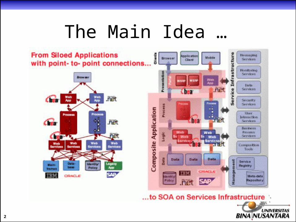
The Main Idea …
2

Mapping SOA to Business
• Analyze– Study processes and identify functionality required.
• Develop– Harvest functionality from existing IT assets,
develop new functionality, and ensure that all services have clear service-level agreements.
• Utilize– Orchestrate services into processes, measure
alignment with strategy, and identify opportunities for optimization.
3

Best Practice Methodology
4
* taken from BEA System SOA Domain Model
SOA Roadmap
• Is a must to successfully planning your SOA implementation.
• Benefits of SOA will be realized only if there is balance between the long-term goals and the shorter-term needs of the business.
• SOA roadmap provides an iterative and incremental way to capture (and recapture) your organization's unique plan as we progress.
5
SOA Roadmap (2)
• Four phases to develop a roadmap:1. Planning.
2. Maturity assessment.
3. Future vision.
4. Definition.
• All phases could be attached to the best-practice methodology.
6
SOA Roadmap - Planning
• Define the scope.
• Establish boundaries and alignments with other IT initiatives and implementations.
• Show the business justification.
• Show alignment of existing and future business scheme.
7

SOA Roadmap – Maturity Assesment
• Business Strategy and Process: – Top-down view of business strategies and
processes.
• Architecture: – Review of current architectures, policies, and
standards.
• Cost and Benefits:– Overview of existing cost structures and
benefits cases.8
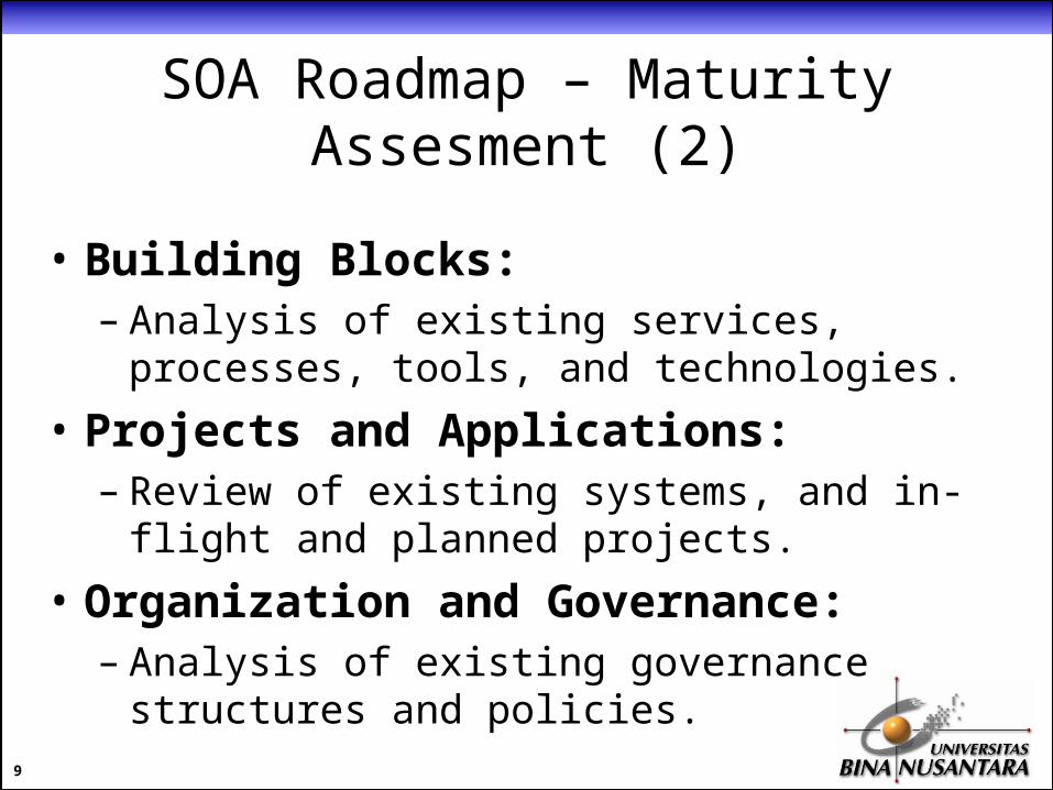
SOA Roadmap – Maturity Assesment (2)
• Building Blocks:– Analysis of existing services, processes, tools,
and technologies.
• Projects and Applications:– Review of existing systems, and in-flight and
planned projects.
• Organization and Governance:– Analysis of existing governance structures and
policies.9

SOA Roadmap – Future Vision
• Business Strategy and Process:– Correlation with business strategies and
processes.
• Architecture:– Guiding principles, requirements, policies,
standards, and reference architecture.
• Cost and Benefits:– Metrics and measurement requirements.
10
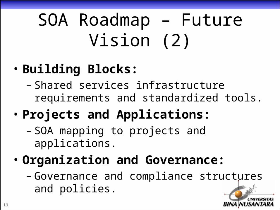
SOA Roadmap – Future Vision (2)
• Building Blocks:– Shared services infrastructure requirements
and standardized tools.
• Projects and Applications:– SOA mapping to projects and applications.
• Organization and Governance:– Governance and compliance structures and
policies.
11
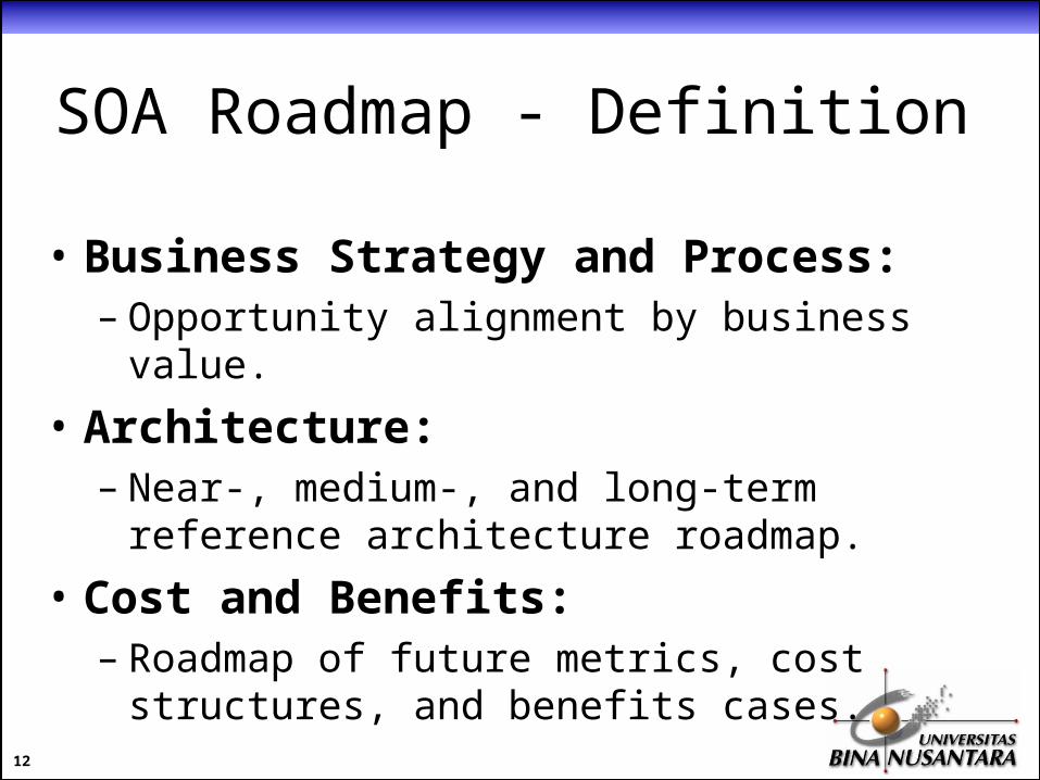
SOA Roadmap - Definition
• Business Strategy and Process: – Opportunity alignment by business value.
• Architecture:– Near-, medium-, and long-term reference
architecture roadmap.
• Cost and Benefits:– Roadmap of future metrics, cost structures,
and benefits cases.
12
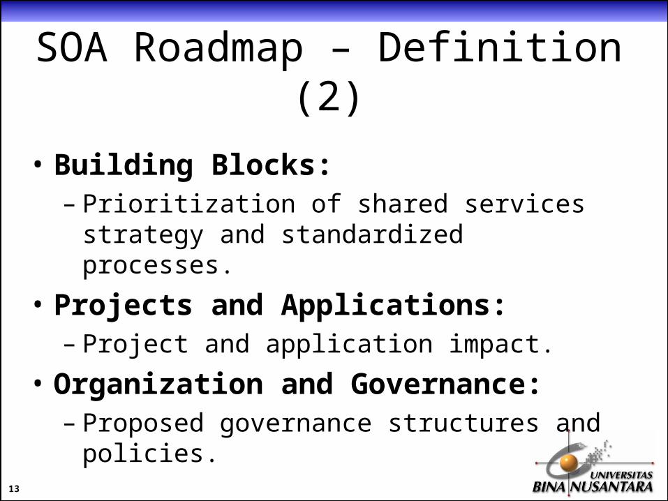
SOA Roadmap – Definition (2)
• Building Blocks:– Prioritization of shared services strategy and
standardized processes.
• Projects and Applications:– Project and application impact.
• Organization and Governance:– Proposed governance structures and policies.
13

SOA “Learn & Adapt” Roadmap
14
15
• Top-Down Deployment– Transforming the system requirements into
SOA architecture.
• Bottom-Up Deployment– Transforming an existing system into SOA
applications.
• Hybrid Deployment– Divide & conquer strategy.
SOA Design Models

16
Top-Down Deployment
• Starts by defining the mechanism for integration.• Describing the service to be exposed first, then
generate the web service applications.• Typical organization will need help from vendor or
integrator for planning, designing, and developing the web service.
• Suitable for a new company or established companies with a certain degree of inter-operability standards.

17
Top-Down Deployment (2)
Fig 1. Top-Down Design Approach

18
Top-Down Deployment (3)
• Benefit:– Consistency
environment and mechanism.– Well supported
internal IT will follow and understand thoroughly about the implementation.
– Scalable easier to evolve the architecture as the business grows or adapts.
19
Top-Down Deployment (4)
• Risk:– Costly
need a well-defined plan (and time) to consolidate various systems into a uniformed standard of architecture mechanism.
– Standardization hard to monitor across large scale organization.
– Maintenance speed slow-response for small changes because everything must be checked and standardized.

20
Bottom-Up Deployment
• Starts by exposing islands of systems into SOA architecture, one-by-one.
• Each system can choose the best approach and technology to do so.
• Consolidation at the high level could varies as well, very heterogeneous.
• Suitable for well-established company who wants to integrate their legacy systems into one big whole system or two companies with legacies that go into a merger.

21
Bottom-Up Deployment (2)
Fig 2. Bottom-Up Design Approach

22
Bottom-Up Deployment (2)
• Benefit:– Rapid response
quickly adapt to newly introduced technologies.
– Quick learning curve various approaches are tested, easier to find best practice.
– Flexibility not locked into specific vendor/technology, lower the overall total cost of ownership (TCO).

23
Bottom-Up Deployment (3)
• Risk:– Harder to maintain
various standards, need lots of resources and expertise.
– Performance may need additional adapter or middleware to enable inter-operabilities.
– Not very scalable changes’ impact could not easily predicted due to variations of approaches/technologies.
24
Hybrid Deployment
• Divide the whole legacy as islands of systems.
• Separation can be based on organizational boundaries (business unit/department) or functional boundaries (front-end, back-end, accounting, etc).
• Integrate islands of systems into one big whole system using a strict standard mechanism (like top-down approach).

25
Service Modeling Process
Fig 3. Sample Service Modeling Processes

26
Service Modeling Guidelines
• Consider potential cross-process and intra-process reusability.– Task-centric business service candidates.
• Factoring process-related dependencies.
• Model for cross-application reuse (extendibility).
• Think about further decomposition.– Is your decomposition granular enough?

27
Service Modeling Guidelines (2)
• Identify explicit boundaries for every logical units of work (autonomous principle).
• Prevent logic boundary slip.– Avoid feature overlapping redundancy and
performance issues.
• Emulate process services when not using orchestration.– Create a master controller business service that
simulates a process service preparing for orchestration composition model.

28
Service Modeling Guidelines (3)
• Point toward a balanced model.– Trade offs between: business requirements,
consistent standards, and industry conventions.– Measure the balance by how well it addresses
the short and long term goal of your company.
• Allocate appropriate modeling resources.– Involve technical, business, and user analysts.

29
Service Modeling Guidelines (4)
• Classify service modeling logic.– Understand the scope of logic represented by
operation, service, or process.– Use classification system (e.g. building block system
a.k.a service modeling units).
• Produce modeling standards.– Sometimes there is no a well-fitted one out there for
your organization.– The most suitable one should be formalized as official
modeling standards.• When the time comes for your organization to move toward
service-orientation, the design approach will no longer be voluntary open to interpretation.
30
BPEL History
• IBM released Web Services Flow Language (WSFL).
• Microsoft created XLANG standard.• IBM & Microsoft collaborates their
technologies to become BPEL4WS.• OASIS supports BPEL4WS and forms
WSBPEL technical committee.• 1st version released in 2002, last version is
2.0, last stable version is 1.1
31
BPEL Concepts
• Provides comprehensive syntax for describing business workflow logic.
• It creates an abstract process that encapsulates the business logic within Web Service.
• It is also coupled with recursive composition and dynamic binding to partners.

32
BPEL and other WS-*
• BPEL and WSDL:– WSDL for BPEL contains process interfaces for the
process service itself.– The service definition for BPEL process has no binding
information so it can be implementation-neutral.
• BPEL and WS-Coordination:– BPEL needs WS-Coordination as its context
management framework.– It utilizes WS-Transactions to manage long running
transactions.

33
BPEL and other WS-* (2)
• BPEL and XPath:– BPEL can use it as standard location syntax,
there are 2 extensions for XPath.
• BPEL and WS-Addressing:– BPEL uses it as standard address format
representation.

34
BPEL Process Descriptions
• Defines workflow consists of sequence of events based on predefined conditions and/or logic.
• Two types of activities within workflow:– Basic activities.
• Primitive workflow functions.
– Structured activities.• Sequential functions to create workflow logic.

35
BPEL Basic Activities
• Contain functions:– receive: identifies partner services that can access
or invoke the process.– invoke: identifies partner services that can be invoked
by the process.– reply: identifies partner services to whom the process
should reply to.– throw: exception handling that shifts processing to the
corresponding logic.– wait: suspend processing for specified amount of time
or until exact time stamp is reached.

36
BPEL Structured Activities
• Contain functions:– sequence: establishes the order to execute
activities.– flow: contains a list of activities that can be
executed concurrently.– switch: provides conditional logic construct
like select-case concept.– while: provides conditional logic construct like
do-while loop concept.

37
BPEL Process Structure Elements
• process: the root element that hosts the entire process definition.
• partnerLinks: represent partner services and their role allocations.
• variables: establish state information management system for long-running tasks.
• faultHandlers: define responses for various error conditions.
• sequence: establish the order of execution.

38
<process name=“TheProcess” ...> <partnerLinks> ... </partnerLinks> <variables> ... </variables> <faultHandlers> ... </faultHandlers> <sequence> ... </sequence></process>
BPEL Process Structure Elements (2)

39
BPEL partnerLinks
<process name=“TheProcess” ...>
<partnerLinks>
<partnerLink name=“purchaseClientService” ...>
...
</partnerLink>
<partnerLink name=“purchaseServicePack” ...>
...
</partnerLink>
</partnerLinks>
</process>

40
BPEL partnerLinks (2)
Fig 4. partnerLink connecting two respective portTypes

41
BPEL variables
<process name=“TheProcess” ...>
<variables>
<variable xmlns:Order=“http://www.order.ws/”
name=“OrderStatus”
messageType=“literal” />
</variables>
</process>

42
BPEL faultHandlers
<process name=“TheProcess” ...>
<faultHandlers>
<catch faultName=“condition01” faultVariable=“err01”>
...
</catch>
<catchAll>
...
</catchAll>
</faultHandlers>
</process>
43
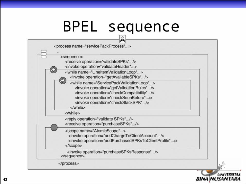
BPEL sequence

44
Binding Partner Services
• Binding schemes for binding partnerLink (so it can be invoked) to a concrete endpoints:– Static design time binding.– Static deployment time binding.– Dynamic binding using lookups.– Dynamic binding using passed-in endpoints.

45
Binding Partner Services (2)
• Static design time:– The process model refer to explicit endpoints.– Useful when the endpoints are meant to be parts of the
business logic.
• Static deployment time:– The process model does not refer to explicit endpoints,
but a set of endpoints is defined at deployment time.– Useful if all instances of a particular deployment of a
process must use the same endpoints.
46
Binding Partner Services (3)
• Dynamic binding using lookups:– Criteria are defined on a partnerLink that a viable
endpoint must have.– Criteria are then evaluated either at runtime or
deployment time to search for providers whose deployed services match.
• Dynamic binding using passed-in endpoints:– the process copying in an endpoint from a variable that
was previously assigned not by the process, but by either a response to an invocation or a request from a partner.

47
Binding Partner Services (4)
Fig 5. Dynamic binding using passed-in endpoints

48
More References
• Please read Service-Oriented Architecture : A Field Guide to Integrating XML and Web Services by Thomas Erl, chapter 12 for more detailed information about BPEL syntaxes.