Embed Size (px)
Citation preview

Paper ID #15305
Designing and Assembling of a Programmable LogicControls (PLC) Labora-tory Trainer and Advanced Research Setup
Mr. Priom Chakraborty, Purdue University - Calumet
Priom Chakraborty, B.S, currently working as a Teaching assistant of Purdue University calumet .He isnow doing his Masters focusing in Mechatronics Engineering Technology. He also worked as lab assistantin AWAKE (Assisting Workforce by Advancing Knowledge for Employment) program in Purdue Univer-sity Calumet. His was a co author of designing of Bottle Washing Machine in Virtual Environment Usingthe New Mechatronics System Design Technology.his recent work is to build a control Panel of Designingand Assembling of a Programmable Logic Controls (PLC) Laboratory Trainer and Advanced ResearchSetup.He has done his B.S. In American international University of Bangladesh(AIUB) his interests are inthe area of programmable logic controlled devices, FPGA system design by Verilog programming, Appli-cation of process control in industrial works, Robot programming. Email:[email protected] LinkedIn:linkedin.com/in/priomchk/
Dr. Akram Hossain, Purdue University - Calumet
Akram Hossain, Purdue University Calumet Akram Hossain is a professor in the department of Engi-neering Technology and Director of the Center for Packaging Machinery Industry at Purdue UniversityCalumet, Hammond, IN. He worked eight years in industry at various capacities. He is working withPurdue University Calumet for the past 27 years. He consults for industry on process control, packag-ing machinery system design, control and related disciplines. He is a senior member of IEEE and heserved in IEEE/Industry Application Society for 15 years at various capacities. He served as chair ofManufacturing Systems Development Applications Department (MSDAD) of IEEE/IAS. Currently, he isserving a two-year term as the chair of the Instrumentation of ASEE (American Society of EngineeringEducation). He authored over 29 refereed journal and conference publications. In 2009 he as PI receivedNSF-CCLI grant entitled A Mechatronics Curriculum and Packaging Automation Laboratory Facility. In2010 he as Co-PI received NSF-ATE grant entitled Meeting Workforce Needs for Mechatronics Tech-nicians. From 2003 through 2006, he was involved with Argonne National Laboratory, Argonne, IL indeveloping direct computer control for hydrogen powered automotives. He is also involved in severaldirect computer control and wireless process control related research projects. His current interests arein the area of packaging machinery system design & control, industrial transducers, industrial processcontrol systems, modeling and simulation of Mechatronics devices and systems in virtual environment,programmable logic controllers, programmable logic devices, renewable energy related projects, wirelesscontrols, statistical process control, computer aided design and fabrication of printed circuit board.
Mr. Vivek Pillarisetty P.E., Purdue University - Calumet
Vivek Pillarisetty is an Indian Graduate Student studying Mechatronics in Purdue University, Calumetin the state Indiana. He has done his under graduation in KLUniversity, Vijayawada, India. He is anoutstanding student and favorite for all of his professors. He is an active participant in both co curricularand extra curricular activities. He is an avid reader and an interpreter. He learns the subject in depth andtries to work hands on whatever he learns. He is currently doing his research in packaging technologyunder Professor Akram Hossain in Purdue University, Calumet. After seeing his insight, the Professoroffered him a Teaching Assistant position in the laboratory for guiding the students in the subject ofMechatronics.
c©American Society for Engineering Education, 2016
Page 1 of 14
Designing and Assembling of a Programmable Logic
Controls (PLC) Laboratory Trainer and
Advanced Research Setup
Abstract:
A Programmable Logic Controller (PLC) is an industrialized computer control system that
constantly monitors the state of input devices and makes decisions based upon a custom program
to control the state of output devices. Almost any production line, machine function, or process
can be greatly enhanced using this type of control system. However, the biggest benefit in using a
PLC is the ability to change and replicate the operation or process while collecting and
communicating vital information. It is also a modular system. It can be mixed and matched the
types of Input and Output devices to best suit of any laboratory application and industrial control
application.
Training setup consists of an industrial grade PLC, Variable Frequency Drives, Servomotors
coupled with drives, induction motors, Human Machine Interface (HMI), industrial networking
capabilities, and many other ancillaries. The setup can be used for demonstrating the principles of
programmable controllers and sequence control systems, advanced cam profile and advanced
computation for controlling industrial processes. It is suitable for training both basic and advanced
principles of PLC. Industrial grade PLC components are permanently mounted on the panel; it is
also coupled, activated and controlled with numerous configurations such as with Variable
Frequency Drive (VFD), servo drive, servo Motor, and induction motor, along with Human
Machine Interface (HMI).This Laboratory Trainer and research setup system is fully integrated
with PLC Motion Animation software that will help students observe and understand the control
logic behind the operation of industrial PLCs. The software tool can be used as an offline and
online animation tool with its collection of sample HMI applications. The trainer can be used
alternately for operation and control of industrial manufacturing processes. The example ladder
logic program in the trainer describes the methods of running servomotor and servo drive that are
widely used in almost every industry where automation is required. Smart vision checking system
which is used for sorting and many other purposes can also be interfaced with the setup. This setup
has at least two VFD to control various functions of induction motor. Such as conveyor speed,
acceleration, and many other motion related aspects of an induction motor.
The combination of software and hardware offers practical and effective trainer and research
engine for industrial control and manufacturing. Also help students to know about smart vision
checking system, servo drive, servomotor, induction motor, Variable Frequency Drive (VFD),
HMI, industrial networking, and interfacing with real world packaging machines. In addition, one
of the main advantages of this trainer setup panel is its modular capability. This trainer setup can
be modified, coupled with any industry related control system that might need in the future for

Page 2 of 14
training purpose. Above all, this laboratory training and control panel setup is performed in two
stages. First, the machine design and electrical control for the entire operational process is
conducted and then the study of effectiveness of re-configurable and portable Programmable logic
controller system with proper statistical analysis.
Introduction:
Programmable Logic Controllers(PLC) are predominately laboratory based subjects as they
require “hands on” electrical wiring, interface to industrial electrical components, to Human
Machine Interfaces (HMI) and may be networked with conveyor system, vision checking system,
Servo motor etc. (Rohner, P. (1996). PLC). As PLC courses evolve to incorporate the IEC 6-1131
defined programming languages with the resultant extra software theory learning requirement and
an increasing demand for in-company courses, a requirement arises for a PLC system which is
portable, reconfigurable and can be accommodated in a training or class room with the small
control system included conveyor, servo motor, Cognex Vision Checking etc.
This research started with performing the studies about each and every method how a small control
system can be controlled by Programmable Logic controller in automation world. For an instant
as the PLC is part of an automated system there are several modules that are included to this
terminal. Those modules are software engineering, electrical design, and in some cases,
mechanical design. Software engineering includes applying a Software Development Life Cycle
(SLDC) approach to the system being designed and the ability to write the control program to
control a real time control system. Electrical design encompasses electrical panel design (and
construction) to the relevant standard. The PLC apart from being run as a “stand alone” is now an
integral part of a system ranging from agricultural engineering to mechatronics and industrial
automation. PLC application, as for all control engineering, it must deliver “a balance of practical
skills and theoretical knowledge” and as such are laboratory based. Increasingly, in response to
demands from industry PLC courses are being run in-house, in training rooms, away from the
traditional venue of the automation laboratory using hardwired “kits” and PC based simulators
(Bolton, W., & NetLibrary, Inc. {2006})
This system also describes the methods of running servo motor by servo drive (ultra 3000) which
is widely used in almost every industry where automation required. Nevertheless it also includes
conveyor system which is used almost everywhere where any kind of moving of product from
one point to another is necessary in industry , and also Cognex Vision Checking system which is
used for sorting out the product based on required standard in everywhere. Not only the system
currently being run by Ladder Logic programming and digital I/O it also gives the idea about
analogue I/O and the Sequential Function Chart (SFC) programming language, data capture and
Overall Equipment Effectiveness (OEE) measurement. For the Ethernet module OEE data

Page 3 of 14
collected by the PLC networked and presented on remote PCs as part of a Management
Information System (MIS).
Purpose of Study:
The main reason for this study is that for many years, industrial processes were not directly
monitored. The input and output were not given keen attention, which resulted into wastage (Jha,
2008). Also, the operations of machines in an industry were not well monitored. There was need
for a system that can continuously monitor the input and output of machines. As a result, the
research to design and fabricate a programmable logic controller was started (Bolton, 2006). This
system will help monitor elements such as safety, fire, smoke, radiation emission among others.
The best method to be used in this kind of research is the casual study. This is because the
investigation is done in an industry where one does not necessarily have to attend classes.
Some of the data that was collected within the industry when the machines were investigated are
as shown in the table below.
Factors investigated Data collected before the
installation of the PLC into the
machines
Data collected after the
installation of the PLC into
the machines
The intensity of smoke
emission
70 % 35 %
Number of accidents monthly 25 9
Emission rate in the industry 90 % 45%
Fire outbreaks in the industry 11 3
Table: 1(a) Comparison of industrial operation before and after PLC installation
Another purpose is that the study must help come up with a better design for the programmable
logic controller. The new design must be more developed compared to the previous versions. PLC
training module must always be able to perform a project or task correctly. This is possible because
the PLC is equipped with a conveyor belt, robot arm and wired to a controller (Bolton, 2009).
PLC is used in the communication and technology industry hence making those industries very
essential for research. The device is applied in the communication industry to monitor various
elements making communication easier. Also, the PLC has become an important element of
automation engineering especially where machines are involved. This qualifies the manufacturing
and production industries this research. Improvements made on the logic controller are the key, as
they help it integrate safety engineering, communication and technology (Jha, 2008).

Page 4 of 14
Research can be shown based on data providing below between before installing PLC. and after
installation.
Data type Before installation of the PLC After installation of the
PLC
Number of workers 125 130
Number of accidents 30 15
Number of victims to injuries
every month
20 10
Number of incidents of
firebreak outs every month
7 4
Numbers of machines that
breakdown every month
100 60
The intensity of the smoke 65% 40%
The rate of emission of smoke 2.84 1.24
The rate of output to input 70% 90%
The percentage of material
wastage
60% 25%
The volume of production
every month
78914 items 107524 items
The possibility of worker
absence
70% 32%
Table: 1(b) Comparison of Industrial Operation Before and After PLC Installation
Sources of Data
There are three sources that were employed in this research. Since the research data was collected
from industries, the sources were primary and secondary. However, it is important to note that
since this was an academic research paper, it majored in the primary source for the purpose of
getting firsthand [information (Kahn, MacQueen & Plotkin, 1984). Some of the examples of the
primary sources employed by the research in the design and fabrication of the PLC included;
Business letters that were wrote by the experts in the field of design and fabrication in the
industries where research happened
Business diaries and journals kept by the industries also helped in data collection
Also, the engineering drawings, sketches, photographs & paintings among others
The research concentrated on banners, advertisements and posters
The company’s news footage e.g. the videotapes, newsreels and audiotapes
Page 5 of 14
Component Description:
Programmable logic controller (PLC) is an industrial computer system that monitors continuously
the state of a machines input devices and decides upon a program to control the output device. For
many years, PLC’s have been widely used in a variety of applications which are the most important
control elements of several subsystems requiring moderately slow data monitoring. These are
personal safety, the radiation control, smoke, and fire alarm. PLC’s are very crucial for monitoring
and controlling a process. There are inputs and outputs which can be categorized into two types,
which are logical and continuous. The input terminals in the PLC helps in interpreting high or low
logical states from switches and sensors whereas the output terminals help in signaling power
lights, contactors, small motors, solenoids and other devices. As they are industrial computers,
their input and output signals are typically 120volts AC, similar to electromechanical control
which they are designed to replace. The PLC module for training gives those students pursuing
mechanical engineering more knowledge in mechatronics.
Servo Motor Motion Control:
Integration of PLC with a servo motor is quite easy. All that is required is that you have right
settings, build right wiring and an accurate program. Right wiring is a key, particularly when you
purchase the servo engine control with a driver.
Correct Wiring: Output the servo RUN signal to the motor and reset signal to any alarm. You
need feedback from the AC servo motor encoder for the input to the PLC from the servo driver.
Tapping into the PLC pulse output complete signal from servo driver is also another option.
Writing of the Program: You can control a servo motor using ladder logic to give an effective
and continuos supply of pulses in which the pulse can stop when the program instructs it to stop.
Servo Motor Control Using PLC
There is linear servo system and motion control system where each is unique from the other. Linear
servo system supplies pulse into the motor drive then the drive gives power through the PWM to
the AC servo motor. Feedback is in return given by encoder to the driver and driver does the error
counter. Motion control system supplies pulse to the motion control unit, which gives analog input
0-10v to motor, driver. The motor driver gives power through PWM to the AC servo motor.
Feedback is in return given by the encoder to the driver and driver gives error notification to the
motion control unit to conduct the error counting (Rohner, P. 1996).
How Servo Motor Works
They are specifically designed to be used in control applications and in robots. They are also used
for specific position and speed control consisting of a suitable motor, position sensor, and
sophisticated controller. DC servo motor and AC servomotor are the categories of the servo motor.

Page 6 of 14
A servomechanism is a closed loop system, consisting of controlled device, output sensor,
controller, and feedback system. Its’ application is most probable when position and speed are
controlled.
HOST
COMPUTER/
SOFTWARE
TOOLS
MOTION
CONTROLLERAMPLIFIER MOTOR
POSITION
SENSOR
ENCODER
V I
POSITIONPOSITION FEEDBACK
POSITION COMMAND
Theta
C
Figure: 1 Servo Motor Working Principle
Servo motors are used to control speed and position where the mechanical position of the shaft can
be detected by use of potentiometer coupled to a motor shaft through gears. The current position
of the shaft is then converted into electrical signal and compared with command input signal.
Modern servo motors use electronic encoders or sensors to sense the position of the shaft. Based
on the required position of the shaft, the command input is given.
If the feedback signal is different from the given input, an error signal is generated. The error is
applied as the input to the motor which leads to rotation of the motor. When the shaft is at the
required position, error signal becomes zero making the motor stay standstill holding the position.
Design And Assembly of Trainer Panel:
This trainer Panel is designed in mainly three steps
1. Mechanical Design of the trainer
2. Electrical Schemtic for wirning the component
3. Devlop the ladder Logic for the controller
1.Mechanical Design:
In this project the mechanical frame is built using the AutoCAD® software and
SOLIDWORKS. This is the very first step of building this trainer Panel. To design the trainer

Page 7 of 14
Panel Components were pre-selected, which gave the idea how it has to be built in a way that the
entire component can be place in it in a systematic way, and also keeping in mind that future
expansion of component is possible if needed.
Figure 2: 3D Design (Preliminary) of the Trainer Panel.
For this trainer panel, a well-designed cubic structure was built with keyboard and monitor
mounting hardware for the trainer computer. The first 3D design of the panel was helpful to divide
the space into 6 equal sub-panels and layout the component. The bottom most row consisting of
two sub-panels were fixed to mount 2 Allen-Bradley MPL series Servo motors.

Page 8 of 14
Table 1: Finalized Drawing of Different View of the Trainer Panel

Page 9 of 14
Figure 3: Real time PLC Laboratory Trainer Panel

Page 10 of 14
Some of the important panel components can be known from the table below:
PLC and I/O Modules Parts No
Compact Logix PWR 1768-PA-3/A
Ethernet Module 1768-ENBT/A
Sercos Interface 1768-M04se/A
Compact Logix L43 1768-L43/A
Isolated Relay out 8pt. 1769-OW81/B/3
Sink/Source Input 16pt. 1769-IQ16/A/2
End cap 1769-ECR
PowerFlex 4 cat no 22A-B2P3N104
Servo Drive
Line Interface Module 2094-AL50S
Ultra 3000 servo drive 2098-DSD030-SE
Ultra 3000 servo drive 2098-DSD030-SE
Line Filter 2090-XXLF-X330B
IAM 2094-AC16-M03-S
AM1 2094-AM03-S
AM2 2094-AM03-S
AM3 2094-AM03-S
Motor Cable
Motor Feedback Cable
Feedback connector
Servo Motor
MPL series servo Motor MPL-430P-MJ24AA
Eye Vision Checking System
Cognex Vision checking System 5100C
HMI
Panel view 1000 plus
Table 2 List of Components for Trainer Panel
2. Electrical Layout
After the Mechanical design it is needed to identify the I/O of the components which are mounted
on the panel. The next step was to make electrical panel layout and wiring diagram of the electrical
wiring. Depending on the I/O of the component the wiring diagram of the machine has been
changed. Here is the main power diagram of electrical Layout for the trainer Panel

Page 11 of 14
Fig 4: Main Power Diagram of Ultra 3000 Servo Drive in The Trainer Panel
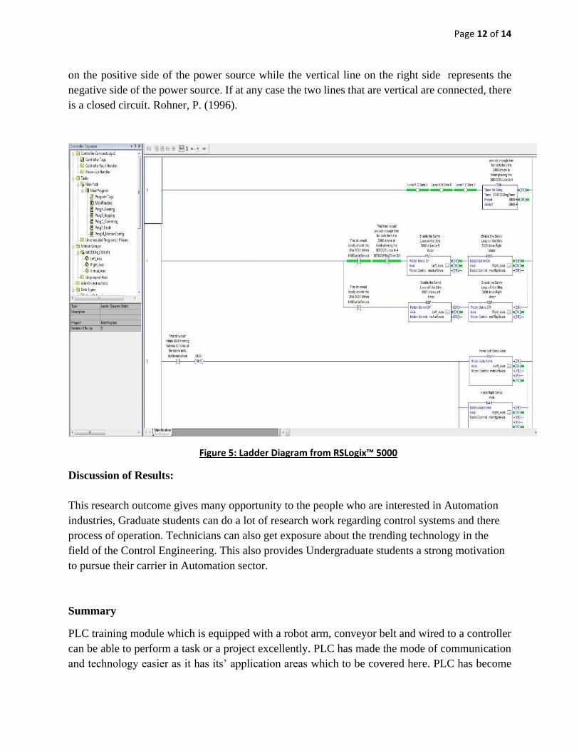
4. Ladder Logic
After completing the electrical wiring the Ladder logic of PLC has been designed. Using the
RSLogix™ 5000.It is quite hard to beat the simplicity and usefulness of ladder diagram
programming when it is used to replace timers, counters and relays. It is, therefore, a graphical
programming technique that came from electrical circuit diagrams. The logic in ladder diagrams
flows from left to right where the diagram can be divided into subdivisions called rungs. With an
input of instructions, which lead to single output instruction are every rung containing function
block instructions which are complicated. In other words, the programming method is vertical
which means that the user can visualize what the program does. The vertical line on the left stands
Page 12 of 14
on the positive side of the power source while the vertical line on the right side represents the
negative side of the power source. If at any case the two lines that are vertical are connected, there
is a closed circuit. Rohner, P. (1996).
Figure 5: Ladder Diagram from RSLogix™ 5000
Discussion of Results:
This research outcome gives many opportunity to the people who are interested in Automation
industries, Graduate students can do a lot of research work regarding control systems and there
process of operation. Technicians can also get exposure about the trending technology in the
field of the Control Engineering. This also provides Undergraduate students a strong motivation
to pursue their carrier in Automation sector.
Summary
PLC training module which is equipped with a robot arm, conveyor belt and wired to a controller
can be able to perform a task or a project excellently. PLC has made the mode of communication
and technology easier as it has its’ application areas which to be covered here. PLC has become

Page 13 of 14
an important element of automation engineering as it integrates safety engineering, technology,
and communication. This trainer Panel can help student to learn about the configuration of servo
motor, ladder logic Programming, configuration OF Vision checking system etc. more importantly
student can get the idea of the real time control system which will be helpful for their future career.
This PLC Laboratory setup replicas the industrial environment that will help the system of
education to reduce the transition gap across the theoretical knowledge provided and to the
industrial Equipment. By including the process of Design, assembly and Programming in the
Laboratory Experiments and getting Hands on with the setup will result in an exposure where the
student can involve in the process of PLC Design for the requirements by including this into the
curriculum. This training module can act as a platform to the students so as to have their ladder
logic downloaded into the PLC and observe the operation of the servo motors, conveyors and
integrate the sensors to their logic. The data given about the comparison of Industrial Operation
before and after PLC installation will show how the expertise in this technology will help the
industries in a way to have an economical production. So by having the students knowledgeable
enough in this field will reflect in the results much better than to present days.
Page 14 of 14
References
[1] Bolton, W., & NetLibrary, Inc. (2006). Programmable logic controllers. Amsterdam:
Elsevier/Newnes.
[2] Kamel, K., & Kamel, E. (2013). Programmable logic controllers: Industrial control.
[3] Rohner, P. (1996). PLC: automation with programmable logic controllers: A textbook for engineers
and technicians. Sydney: UNSW Press.
[4] Shahin, T. M. M., EDC 2002, & Engineering Design Conference. (2002). Computer-based design:
Engineering Design Conference 2002 [held at King's College London, UK on the 9-11 July 2002].
Bury St. Edmunds [u.a.: Professional Engineering Publ.
[5] Bolton, W. (2009). Programmable logic controllers. Amsterdam: Newnes.
[6] Jha, N. (2008). Research methodology. Chandigarh: Abhishek Publications
[7] Phillips, P., & Stawarski, C. (2008). Data collection. San Francisco: Pfeiffer.
[8] Axinn, W., & Pearce, L. (2006). Mixed method data collection strategies. Cambridge: Cambridge
University Press.
[9] Hartwig, F., & Dearing, B. (1979). Exploratory data analysis. Beverly Hills, Calif.: Sage
Publications.
[10] Kahn, G., MacQueen, D., & Plotkin, G. (1984). Semantics of data types. Berlin: Springer-Verlag.