Embed Size (px)
Citation preview

O
pera
tion
Gui
de
Designer Software
Part Number 2-450202-010 manual revision v2.0 2nd March 2009

Page 2
Vision Net Designer
© Philips 2009

Page 3
Vision Net Designer
© Philips 2009
Table of Contents
Welcome 6Vision.Net 7 Vision.Net Overview 8 Communications 9Vision.Net Designer Software 10 Vision.Net Designer 11 Menus 12 File 12 Tools 14 Setup 15 Interface 16 Operating Style 18 Mode Maps 19 Real Time Clock 21 Maps: Display/Unlock All 22 Help 22 Tool Bars 23 Main Tool Bar 24 Status Bar 26 Status Bar 27 My Network Tree 28 Group/Rooms 29 Control Stations 30 Buttons 31 Slider Faders 33 Station ID 34 Saving and Loading Station Configurations 35 Saving to a Station 36 Loading from a Station 37 Custom Panels 38 Touch Screens 39 Touch Screen Tool Bar 41 Screen Design 43 Touch Screen Tabbed Views 44 Touch Screen Buttons 47 Touch Screen Slider 48 Touch Screen Slider Panels 50 Touch Screen Raise and Lower 51 Touch Screen Text 52 Touch Screen Clock 53 Loading Touchscreen 55 Output Devices 57 Adding Devices 58 Simulations 62 Palette OS 63 Real Time Clock 66 Timed Events 67Vision.Net Component Connections 71

Page 4
Vision Net Designer
© Philips 2009
Button Stations 72 DMX Interface 73 Fader Stations 75 RS232 Station 76 Palette 78 Portable Stations and Screens 79Appendix 80 Button and Event Actions 81 Smart Buttons 86 Touch Screen Maintenance 87 Trouble Shooting 88 Offices and Service Centres 89

Page 5
Vision Net Designer
© Philips 2009
Page 6
Vision Net Designer
© Philips 2009
Welcome to Vision.net Designer
Date: March 2009
Software v2.0.0 or later
Congratulations on the purchase of your Strand Lighting Vision.net System software.
For general help, use the Contents, Index or Search tab on the left.
Getting Technical Support
For technical support, please refer to the Strand Lighting Offices and Service Centres
Part Number 2-450202-010manual revision v2.0.1b 2nd March 2009

Page 7
Vision Net Designer
© Philips 2009

Page 8
Vision Net Designer
© Philips 2009
Vision.net
Overview.
The Vision.net System is designed to control architectural lighting by distributing both power and intelligence.The system provides processing power and control at each respective Master or Remote Station, eliminatingthe need for a central processor.
Master Stations provide individual control for up to 15 channels, 8 scenes plus “Off”, all with adjustable fadetimes. Multiple Stations may be linked together for control of up to 127 Channels and 32 preset scenes.
By combining Vision.net Master Stations with Vision.net Preset Stations, the system provides remote access toscenes, Master Raise/Lower control, Multi-room partition control, or Master Station Lockout.
In the basic configuration mode the room number can be set on Vision.net Master Stations using the front panelbuttons, without removing the Master Station from the wall, and without the need for a computer.
Vision.net Touch Screens allow fully customised displays that are easy to configure and may be programmedover an ethernet link. Portable and Fixed screen options are available.
Vision.net Master Stations are compatible with Strand Lighting A21, R21, C21 and EC21 Dimming Cabinets andthe Vision.net DMX512 Output board.
Vision.net products are controlled by the Vision.net System protocol. All Vision.net control devices must beconnected to the Vision.net system and given a unique ID (or address) in order to interact properly. The IDidentifies the device on the network and allows the device to avoid network collisions when transmitting data
Vision.net Components
Components that make up a Vision.net work include, but are not limited to the following:
C21 and EC21 Dimmer Racks A21 and R21 Dimmer Racks Contact Relay Panel Vision.net DMX512 Output Board N21 Network Nodes 8 Push Button Control Panels 3 Slider Stations and Slider Master Stations 6 Slider Stations and Slider Master Stations 9 Slider Stations and Slider Master Stations 12 Slider Stations and Slider Master Stations 15 Slider Stations and Slider Master Stations Vision.net Connection Stations Palette and Light Palette Control Consoles Rack Palette Architectural Control System 7", 10" and 15" Touch Screen Panels

Page 9
Vision Net Designer
© Philips 2009
Vision Net Communications
Overview
A Vision.net system uses an RS485 multi drop cabling system for communications between the various deviceson the Vision.net network. This includes Buttons Stations, Fader Stations and Various other devices such astouch screens and other output devices.
In addition to using RS485, certain devices can also use an Ethernet connection for communications. This forexample includes the latest Touch Screens and the Vision.net Designer software. Using Ethernet as thecommunications medium for Touch Screens, allows you further enhanced control of the screens, allowing newsoftware and configurations to be uploaded directly from Vision.net Designer.
A gateway will be required to convert the Ethernet signals to the Vision.net RS485 data. Suitable gateways canbe provided and you should consult Strand Lighting for more details.
Vision.net uses distributive processing techniques, whereby reliabilty is significantly increased over those ofcentralised processing systems. Intelligence is distributed across the network with output devices storing onlythe data that they need, reducing cost. As result of in the case of a failure, the fault is locally contained, ratherthat compromising the entire system, as would be the case in a centralised system.

Page 10
Vision Net Designer
© Philips 2009
Page 11
Vision Net Designer
© Philips 2009
Vision.net Designer Software
Overview
Vision.Net Designer is a software program allowing the configuration of a Vision.net system to be designed,monitored and modified.
The configuration tool is a powerful Graphical application, allowing devices to be added, monitored or changedin an easy to use "Point and Click" environment. Common features, such as Copy & Paste and other Windowsenvironmental tools make designing your system a fast and pleasurable experience.
Most items are selected from Tool bars, which are context sensitive to the area that you are working in. Properties of these items are then set, either using the Properties Icon on the device or toolbar, or by using themouse and right clicking to expose a drop down list of actions for the device.
The main screen is divided into areas, Device Tree, Devices Window and Status Bar. In addition to these thereis the menu bar with options of File, Tools and Help.
Note: When you first open Vision.Net Designer, it will open in one of three Operating Styles. Youcan change the current operating style from the Style Selection button on the toolbar. Apassword may be required to change the style (see Tools - Setup in the Menu Bar).
Page 12
Vision Net Designer
© Philips 2009
File
File Menu
The File menu gives access to File actions, for example building a New configuration, Opening existingconfiguration files, Saving Configuration files and setting the system to work off line.
Tip: When not connected to a Vision.net system, you should ensure that the “Work Off Line”option is selected in the File menu
New Displays a New Vision.net Project
Open Open an existing Vision.net Project
Recent Files Produces a list of recently used Vision.net Projects
Save Save your current Vision.net Project
Save As Save a copy of your Vision.net Project as a new name or in a new folder.
Page Setup This opens up the Printer properties, which is used when printing OutputDevice information. See Output Devices for more information

Page 13
Vision Net Designer
© Philips 2009
Work Off Line Selects Off Line working
Exit Closes Vision.net Designer

Page 14
Vision Net Designer
© Philips 2009
Tools
Tools Menu
The tools menu gives access to the system Setup screens and allows the configuration of the communicationsettings for connection to the Vision.net network.
Setup Displays the Setup Screen
Maps:Display/UnlockAll
Clears any display modes and unlocks statons.

Page 15
Vision Net Designer
© Philips 2009
Setup
Setup
The Setup tool displays the setup dialog where you can select a different Operating Style, setup Mode Mapsand select settings for a Real Time Clock.
Setup dialog box

Page 16
Vision Net Designer
© Philips 2009
Interface
Serial Port
This allows the choice of the serial port that Vision.net Designer will use to communicate with components ofthe system.
Ethernet Port
Selecting the Ethernet option, allows Vision.net Designer to connect to the Vision.net network over an Ethernetlink.
Note: When connecting to an Ethernet network, Vision.net Designer must be connected to thesame subnet as the Vision.net Gateway.

Page 17
Vision Net Designer
© Philips 2009

Page 18
Vision Net Designer
© Philips 2009
Operating Style
Operating Style
The Vision.net designer software runs in one of three different modes. You can configure the system toautomatically start in one of these modes. The default mode of operation will be Designer Style.
Monitor Style
In Monitor Style, Vision.net Designer allows the software to mimic the state of the Vision.net network, but not tochange the state of devices.
Mimic Style
In Mimic Style, Vision.net Designer allows the software to mimic the state of the Vision.net network, and tochange the state of devices.
Designer Style
In Designer Style, Vision.net Designer allows the software to change all aspects of the system.
Tip: You can force Vision.net designer to start up in Mimic or Monitor Style. You can also seta password to protect the Designer Mode by selecting the “Password Required to ChangeStyle” and entering a numeric password.

Page 19
Vision Net Designer
© Philips 2009
Mode Maps
Mode Maps
Mode Map Configuration Screen
Different Modes are used to mask features and facilities of a system to reflect the current state of operation. You can define up to 8 different modes, each mode can be password protected if desired.
The different modes and their passwords are set in the setup in the Mode Maps section of the Setup.
Mode Name This is an area for text entry, allowing you to enter a name to easily identifythe mode.
Password This is a six number password required to change the system to therequested mode.
Note: Password Entry is only possible from a touch screenon the system.
Passwords
When a user selects a different mode from a touch screen, a numeric keypad will appear allowing a passwordto be entered.

Page 20
Vision Net Designer
© Philips 2009
Example Keypad
For example you might configure two modes of operation, one for Daytime operation and one for Night Timeoperation or one for Show Mode and one for Rehearsal Mode.
Note: A default "Admin Mode" with a password of 1234 is always set whenever you create anew Vision.netDesigner file.
Page 21
Vision Net Designer
© Philips 2009
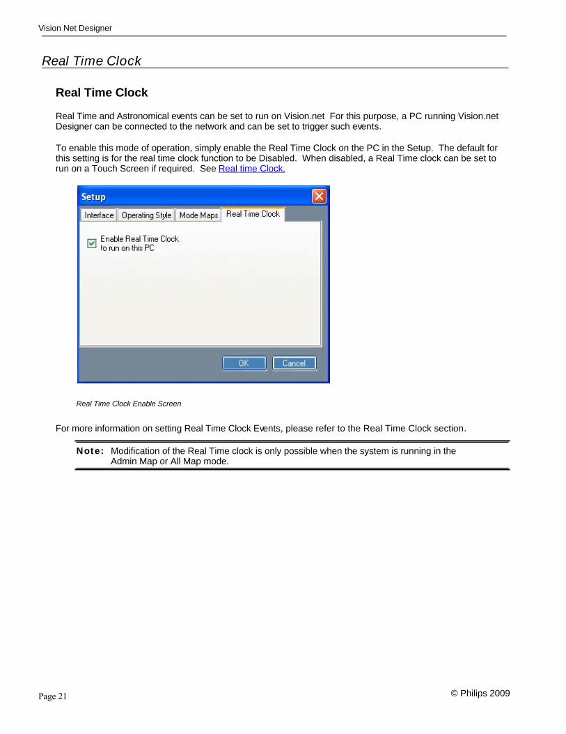
Real Time Clock
Real Time Clock
Real Time and Astronomical events can be set to run on Vision.net For this purpose, a PC running Vision.netDesigner can be connected to the network and can be set to trigger such events.
To enable this mode of operation, simply enable the Real Time Clock on the PC in the Setup. The default forthis setting is for the real time clock function to be Disabled. When disabled, a Real Time clock can be set torun on a Touch Screen if required. See Real time Clock.
Real Time Clock Enable Screen
For more information on setting Real Time Clock Events, please refer to the Real Time Clock section.
Note: Modification of the Real Time clock is only possible when the system is running in theAdmin Map or All Map mode.

Page 22
Vision Net Designer
© Philips 2009
Maps: Display/Unlock All
Maps: Display/Unlock All
Show All Maps, allows the Vision.net Designer to be defaulted back to a mode where all components can beseen, even if that have been hidden in certain modes. This can be useful where elements have been hidden;as a result of selecting a mode, when testing.
When show modes are shown, Enable All Modes will briefly display in the Status Section of the screen.
Vision.net Designer Status Bar
Help
Help Menu
The Help menu gives access to
Contents Displays this Help file
Index Displays the Index tab of this help file where you can search by a keyword
Reset Warnings
About Displays the splash screen showing the Product name and current version

Page 23
Vision Net Designer
© Philips 2009

Page 24
Vision Net Designer
© Philips 2009
Main Tool Bar
The Main Tool Bar gives you access to the following
The Main Tool Bar
Save Save the configuration for archive purposes. Vision.net Designer files are xmlbased, making them future proof.
Tip: By using Vision.net Designer in a design team, you canexchange Vision.net Designer files between team membersto convey ideas and operation of the system. Due to thecompact nature of the Vision.net Data files, these are smallenough to be emailed easily.
Add toNetwork
Add to Network drop down list
Use this to add Main items to your Network Tree, these for example are Rooms/Groups, Custom Panels, Touch Screens, Output Devices or Real TimeClocks.
Simulate Use the Simulations buttons to create simulations of Dimmer Racks, or DMXControl Devices.
This will help you get an idea of how your system will work when you install it. Thesimulation tools make understanding your system very easy and it is a very quickway to communicate ideas.
Design Style
Operational Style drop down list
Use the Operation Style button, to choose the mode that Vision.net Designer runsin.

Page 25
Vision Net Designer
© Philips 2009
.

Page 26
Vision Net Designer
© Philips 2009

Page 27
Vision Net Designer
© Philips 2009
Status Bar
A status bar is shown at the bottom of the screen. The status section also shows a progress bar, whenuploading or downloading to the Vision.net network.
Vision.net Designer Status Bar On Line
The small icon on the status bar, allows you to display upto the last 20 commands that were seen on theVision.net network. This is useful for testing and fault finding purposes.
Note: The communications port is enabled or disabled through the File menu and the Work OffLine setting. When working Off Line, the status bar will show as being OFFLINE flashingRed.
Vision.net Designer Status Bar OffLine

Page 28
Vision Net Designer
© Philips 2009

Page 29
Vision Net Designer
© Philips 2009
Concepts
A Group or Room is a collection of circuits and Control Panels, all dedicated to adjusting the lighting in aparticular zone of the building.
Adding a Group to the Network
Using the Main Tool Bar, click on Add to Network and select Room/Group. A dialog box will appear, promptingyou for the Group’s Name and ID number. The ID number will be used as a short cut to refer to this room later.
When the room is added it will appear in the directory tree under Group (Room) with the ID number and Namethat you gave it.
Room Example with Panels added to it
Tip: You can simulate the output of a dimmer rack or input of a DMX device by using the Rackor DMX simulation buttons. See the Simulations section for more details.
Page 30
Vision Net Designer
© Philips 2009
Control Stations
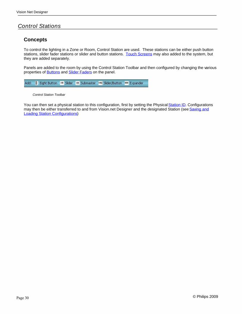
Concepts
To control the lighting in a Zone or Room, Control Station are used. These stations can be either push buttonstations, slider fader stations or slider and button stations. Touch Screens may also added to the system, butthey are added separately.
Panels are added to the room by using the Control Station Toolbar and then configured by changing the variousproperties of Buttons and Slider Faders on the panel.
Control Station Toolbar
You can then set a physical station to this configuration, first by setting the Physical Station ID. Configurationsmay then be either transferred to and from Vision.net Designer and the designated Station (see Saving andLoading Station Configurations)

Page 31
Vision Net Designer
© Philips 2009
Buttons
For each Push Button on a push button station you can configure what action the button performs.
For each button on the station you can then set the following properties:
Button Label A descriptive name for the button or what its purpose is.
Note: When you change the Button Type the Label willautomatically be set to reflect the button type.
Button Type The Button type gives a drop down list of all the button actions you can set. The list contains various button types for example:
Console Button Genlyte Scene (for use with other Genlyte products) Lower Preset Preset On/Off Raise Room Link Select Mode Share Button Smart Smart Mimic Toggle Channel
Depending on the button type, other options will appear see Button Actionsfor more details
Tip: Use the “all buttons on this station have the samestyle” option to quickly change all the buttons to thesame type.
Press and HoldLearn
Vision.net provides a very easy feature for recording Presets in thesystem. By default, preset selection buttons also allow the current sceneto be recorded by pressing and holding the required preset button for 3seconds.
Tip: You may want to disable this feature on certainbuttons to ensure that the lighting levels do notaccidentally become overwritten. Do this byselecting the "Disable Press-Hold Learn" check boxfor the button concerned.
Note: Press and Hold Learn is only available on Presetand Preset On/Off buttons.
Mode Map Using the Mode Map button, you can define if that button is operationalwhen the system is set in different modes. By default the button will beavailable in all modes.

Page 32
Vision Net Designer
© Philips 2009

Page 33
Vision Net Designer
© Philips 2009
Slider Faders
Different fader types can be set depending on the panel type chosen the faders can be either:
Channel Faders. Extensions to another Channel Fader board Submaster faders
Slider Room Here you set the Room that the faders reside in and the number of fadersthat are on the panel.
Number ofSliders
Select the number of faders from the drop down list.
Mode Map Using the Mode Map button, you can define if the faders are operationalwhen the system is set in different modes. By default the button will beavailable in all modes

Page 34
Vision Net Designer
© Philips 2009
Station ID
Setting a Station’s Vision.net Network IDStep 1. Connect the PC running the Vision.net Designer software to the Vision.net Network via
the Vision.netRS232 station, using an RS232 lead. Please contact your local StrandLighting Office for more details on this interface.
Step 2: Set Vision.net Designer to work “On Line”.
Step 3: Select or add the required station from the Network Tree and press the Station Id button.
Step 4: Select Set Station ID and the LED indicators of all unassigned stations will flash.
Step 5: Press and Hold any button on the required station for 3 seconds and the station’s ID willbe set.
Setting a Stations ID Address
Changing the Vision.net Network IDStep 1: Connect the PC running the Vision.net Designer software to the Vision.net Network via
the Vision.netRS232 station, using an RS232 lead. Please contact your local StrandLighting Office for more details on this interface.
Step 2: Set Vision.net Designer to work “On Line”.
Step 3: Select or add the required station from the Network Tree and press the Station Id button.
Step 4: Select Change Station ID and the LED Indicators of all stations will flash.
Step 5: Press and Hold any button on the required panel for 3 seconds and that Station will be setto the current station ID. Any other station that is currently set to that Id will have its IDcleared.
Changing a Stations ID Address

Page 35
Vision Net Designer
© Philips 2009
Saving and Loading Station Configurations
Configurations
Once you have designed your configuration for a particular control station, you can upload the configuration tothe station(see Saving to a Station for more details).
If you have already uploaded a configuration to a Station and want to see what it is, you can also download theconfiguration from the Station into Vision.net Designer (see Loading from a Station for more details).

Page 36
Vision Net Designer
© Philips 2009
Saving to a Station
Saving the Configuration to the StationStep 1. Connect the PC running the Vision.net Designer software to the Vision.net Network via
the Vision.netRS232 station, using an RS232 lead. Please contact your local StrandLighting Office for more details on this interface.
Step 2: Set Vision.net Designer to work “On Line”.
Step 3: Select or add the required station from the Network Tree and set the required mode foreach button as desired.
Step 4: Select Upload & OK and the configuration set in the Vision.net Designers software will besaved to the station.
Example of a Stations Configuration before uploading it to the panel
Note: If the upload process fails, a warning will appear advising that the communications to thepanel are unreliable. If this occurs, check that you have a good connection to the Vision.net network and that there is a panel with the ID that you are trying to download theinformation to. See Trouble Shooting..

Page 37
Vision Net Designer
© Philips 2009
Loading from a Station
Downloading the Current Configuration from the StationStep 1. Connect the PC running the Vision.net Designer software to the Vision.net Network via
the Vision.netRS232 station, using an RS232 lead. Please contact your local StrandLighting Office for more details on this interface.
Step 2: Set Vision.net Designer to work “On Line”.
Step 3: Select or add the required panel from the Network Tree and press the Get Configurationfrom Station button. The current configuration loaded in that panel will be downloaded toVision.net Designer.
Once the information has been downloaded the current configuration of the station will be displayed
Example of a Stations configuration after download
Note: If the upload process fails, a warning will appear advising that the communications to thepanel are unreliable. If this occurs, check that you have a good connection to the Vision.net network and that there is a panel with the ID that you are trying to download theinformation to. See Trouble Shooting

Page 38
Vision Net Designer
© Philips 2009
Custom Panels
Concepts
A Custom Panel selection is a collection of Control Stations that are generally grouped together in a locationand which may control one or more Groups or Zones. An example of this, could be a central Control Roomcontrolling several Rooms or Zones, or a Stage Managers Panel, where control is available for House Lighting,Working Lights and other show state lighting.
Once a Custom Panel is added to the network, individual Panels are then added to this location in the samewas as adding Panels to a Group or Room using this Custom Panel Add Toolbar. See Control Stations formore details.
Adding Custom Panels to the Network
Using the Main Tool Bar, click on Add to Network and select Custom Panel. A dialog box will appear, promptingyour for the Custom Station's Name and ID number.

Page 39
Vision Net Designer
© Philips 2009
Touch Screens
Concepts
Touch screens are top level control components that provide a highly customisable interface to the Vision.netnetwork. They are very flexible and provide a highly intuitive and easy to use way of working with the Vision.netsystem.
Adding Touch Screens to the Network
Using the Main Tool Bar, click on Add to Network and select Touch Screen. As with adding other devices, adialog box will appear.
The Screen Dialog Box
Naming the Screen
You start by giving the screen a name to identify it form others that might also be part of your system. Do thisby entering the name in the Name filed of the screen dialog box.
Choosing the Screen Size
Next you will define the size of the screen to be used. Your choice will depend on the size and type of Vision.net touch screen that you are using and are as follows
QVGA - Quarter VGA Screen (320 x 240)
WVGA - Wide VGA Screen (800 x 480)
VGA - Standard VGA Screen (640 x 480)
SVGA - Super VGA Screen (800 x 600)
XVGA - Extended VGA Screen (1024 x 768)
Screen Styles
Once you have chosen the screen size, you need to define the overall layout template that will be used for thescreen. The four templates that are available are as follows:
Full Screen
Split Screen
Split Screen Horizontal
Split Screen Vertical
Split Screen Horizontal and Vertical
ID Number
As well as a system name, which you entered into the dialog box, you will also need to give the screen anaddress for the system to work with. This you enter into the ID Number box. This number auto increment's
Page 40
Vision Net Designer
© Philips 2009
each time you add a new screen to the system for your convenience.
Tip: If you wish to use Vision.net Designer running in Monitor or Mimic mode, you can designa screen specifically for this purpose. If you do so, set the Virtual Screen option in thedialogue box.
Note: Smart button commands are only sent from the Vision.net Designer PC if the software isrunning in the Design style or it is a virtual Touch Screen when running in the MimicStyle.
Once the screen settings have been decided, pressing OK will add the new screen to the system.

Page 41
Vision Net Designer
© Philips 2009
Touch Screen Tool Bar
The Touch Screen Tool Bar gives you access to the following
Touch Screen Toolbar
Properties This brings up the touch screen properties dialogue box
Export Exports the screen definition so that it can be loaded into thetouchscreen (see Loading Touchscreen)
Duplicate Creates another screen on your system with an identical layout.
Grid Displays or Hides the touch screen alignment grid
Touch Screen Properties Dialogue Box
Using this dialogue, you can configure ScreenSavers, Connections settings and a connection to aPhilips Color Kinetics Show Controller.
Page 42
Vision Net Designer
© Philips 2009
Page 43
Vision Net Designer
© Philips 2009
Screen Design
Designing Screens
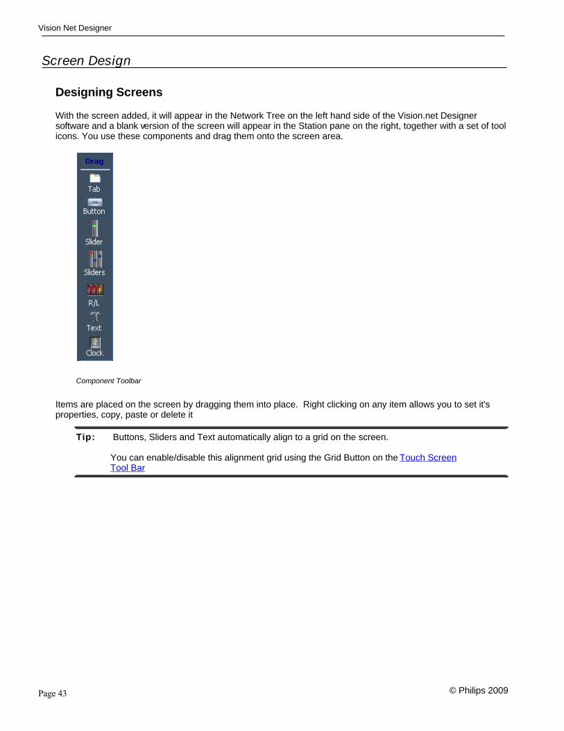
With the screen added, it will appear in the Network Tree on the left hand side of the Vision.net Designersoftware and a blank version of the screen will appear in the Station pane on the right, together with a set of toolicons. You use these components and drag them onto the screen area.
Component Toolbar
Items are placed on the screen by dragging them into place. Right clicking on any item allows you to set it'sproperties, copy, paste or delete it
Tip: Buttons, Sliders and Text automatically align to a grid on the screen.
You can enable/disable this alignment grid using the Grid Button on the Touch ScreenTool Bar

Page 44
Vision Net Designer
© Philips 2009
Touch Screen Tabbed Views
Tabbed Views
Tabbed views give you a display, where you may have a different Vision.net configuration behind each table. Adding a tabbed view to the screen automatically provides you with two tabs.
These tab buttons can be customised see bellow fro more details.
Note: Placing a Tabbed View onto an area of the screen where there is already information willremove them and replace them with the tab view.
Right Clicking in the main body of the tabbed window then gives you options to changethe properties of that particular tab or to delete it or add an additional tab.
Tab Page Properties
Choosing the properties of the tab then brings up a dialog box so that you can set the name of the Tab, the styleof the screen, the Access Level of that Screen, together with a Background colour and image for that screen.
Touch Screen Tab Properties Dialog.
For each Tab Page you can choose one of three different overall styles. These are:
Buttons and Sliders (the default format) Palette Monitor Web Page
Tip: The properties of the screen or items placed on the screen may be set by Right Clicking

Page 45
Vision Net Designer
© Philips 2009
with a mouse.
Background Images
By adding Backround images to a touch screen, you can either add logos or generate a geographic look to yourscreen design.
Bitmap, Jpeg or GIF images can be used as background image, however keep the image file size as small aspossible. Images that are oversized will be scaled to fit the display, but trying to use the native screenresolution is more efficient.
Tip: If you are adding graphics to the screen, try to make sure the image is the sameresolution as the touch screen that you are working with. The native resolutions are asfollows:
QVGA (320 x 240), WVGA (800 x 480), VGA (640 x 480), SVGA (800 x 600) & XVGA(1024 x 768)
Tab Buttons Properties
Right clicking on a tab button allows you to add, move or delete the tab or select the properties of the button.
Using the Tab properties dialogue, you canconfigure the appearance of the button,including the location of tab bar, which caneither be at the Top, Bottom or completelyhidden.
The Sharing Option, allows the tab to beactived by a Share Button on either a touchscreen or control station. Shared Buttonscan also be actived as part of a Smartbutton action and allows for automatedactions.
See Button and Event Actions

Page 46
Vision Net Designer
© Philips 2009

Page 47
Vision Net Designer
© Philips 2009
Buttons
Buttons can be added to the touch screen and their properties set. From the properties you can set parameterssuch as the text to display, the font, colour, style etc, as well as the buttons action.
Touch Screen Button Properties Dialog.
As well as saying what the button does, it is also possible to control when it is displayed, locked or in the case ofpreset buttons, when it is able to used to record or learn presets.
Copying Buttons
Having set the properties of a button, by right clicking and selecting copy and then pasting, copies of that samebutton will be added to the screen. If it is a preset or Toggle action button, each time that you paste it, it willautomatically increase the number the button refers to.
Alternatively, by holding down Control and Left Clicking the icon, a button can be also be quickly copied.

Page 48
Vision Net Designer
© Philips 2009
Touch Screen Slider Fader
Fader
Touch Screen Fader Properties Dialog.
Individual Faders can also be added to the touch screen. In the properties of the slider fader you can select it'sroom channel number etc.
Faders can either be set as a Channel Fader controlling the level of a dedicated circuit or as a Rate Fader,controlling the time of a Preset Fade for the selected room.
Rate Fader
Touch Screen Fader Properties Dialog.
Rate faders are asigned to a Room Number and any preset button, that has the rate setting set as "Slider" will

Page 49
Vision Net Designer
© Philips 2009
use the time set on the rate fader for the fade time.
When you are using the fader to control the rate of the fade of a preset on the touch screen, the Preset button'sRate setting needs to be set to Slider.
Preset Button's Rate Properties Dialog.
If you set the button's rate setting to "Rec Slider" each time the preset is recorded, it will use the time set on therate fader, recording it as the fade time for that preset.
Note: In order to use this feature, both the Rate Slider and the Preset Button needs to be on thesame tab and portion of the touch screen.

Page 50
Vision Net Designer
© Philips 2009
Touch Screen Slider Fader Panels
Fader Panels
Groups of Faders can also be added.
Touch Screen Fader Panel Properties Dialog.

Page 51
Vision Net Designer
© Philips 2009
Touch Screen Raise and Lower Buttons
Raise and Lower Buttons
Raise and Lower Buttons can also be added to the touch screen, allowing individual channels to be raised orlowered using button presses rather than faders. They have the advantage over faders since it allows you alarger number of circuits that can be paged up or down.
Touch Screen Raise and Lower Properties Dialog.
Raise and Lower Styles
Raise and lower buttons can be used either, in proportional or absolute mode.
Proportional Raise and Lower buttons, ramp the circuit up and down and is ideal for use where you are usingportable touch screens.
Absolute Raise and Lower buttons, have the added advantage of providing a level display, however are not agood choice for portable displays, since the it may loose synchronisation with the system and may not displaythe level correctly.

Page 52
Vision Net Designer
© Philips 2009
Touch Screen Text
Text
As well as adding interactive components to the touch screen, text labels may be added as well. In commonwith the main components, the text labels can be set to be hidden or shown depending on the currently selectedMode Map.
Touch Screen Text Properties Dialog.

Page 53
Vision Net Designer
© Philips 2009
Touch Screen Clock
Clocks
You can display an analogue clock on the touch screen.
Touch Screen Clock Properties Dialog.
Options available for the clock are to show the Second Hand and any Pending Real Time clock events.
Note: The use of the secondhand on the screen demands more processor time and as such it isreally only recommended for testing purposes.
Touch Screen Standard Clock Touch Screen Clock with Second Hand and Pending Events
By clicking on "List Events" the events are displayed on the screen, colours are used to denote the status of theevents.

Page 54
Vision Net Designer
© Philips 2009
White: Scheduled for today but has not yet executed
Black: Scheduled for today and has executed today
Red: Disabled
Yellow: Not scheduled for today (Day-of-week or exception list)
Note: You can add a Suspend Clock button to a touch screen to enable or disable any eventsthat are pending on that screen. By using an RTC Group button, you can just disablecertain groups of events, rather than disabling the entire clock.

Page 55
Vision Net Designer
© Philips 2009
Saving the Configuration to the Touch Screen
Once designed the touchscreen configuration can be exported from Vision.net designer. This is done using theExport button on the touchscreen toolbar.
Touch Screen Toolbar Export Dialogue
Manual UpdateStep 1. Select Export from the Touch Screen Toolbar
Step 2. Select "File for touch screen" and select OK
Step 3. Save the “ActiveScreen” into a Folder called "UPDATE" in the root of a USB Memory Stick
Step 4. Place the USB stick with the file into the Touch Screens USB interface and power cyclethe Touch Screen, following the on screen instructions
Note: If you do not create the UPDATE folder and place the ActiveScreen file in this folder it willNOT be loaded into the screen
Ethernet Export (Old touch Screens running code prior to v2.0.0 code)Step 1. Connect Vision.net designer to the same ethernet network as the touchscreen
Step 2. Select Export from the Touch Screen Toolbar
Step 3. Select "Ethernet (Legacy)" and select OK

Page 56
Vision Net Designer
© Philips 2009
Ethernet Export (Touch Screens running v2.0.0 code or later)Step 1. Connect Vision.net designer to the same ethernet network as the touchscreen
Step 2. Select Export from the Touch Screen Toolbar
Step 3. Select "Ethernet"
Step 4. Enter the IP address of the touch screen and select OK

Page 57
Vision Net Designer
© Philips 2009
Output Devices
Concepts
Output devices are devices that connect to the Vision.net Network and drive lights or other controllableelements.
These are typically the Strand Lighting C21, EC21, R21, S21 and A21 dimmer racks. DMX only devices, suchas LED fittings, Moving Lights etc. may also be controlled using the Vision.net DMX interface card.

Page 58
Vision Net Designer
© Philips 2009
Adding Devices
Adding Output Devices to the Network
Using the Main Tool Bar, click on Add to Network and select Output Device.
As with adding other devices, a dialog box will appear, prompting your for the Devices' ID number, Name, Typeand number of devices.
Device Details Screen
Once the device is entered, a spreadsheet style form for will appear for the output device, allowing details ofeach of the circuits to be entered.
Dimmer Output Device Relay Output Device

Page 59
Vision Net Designer
© Philips 2009
DMX Output Device
In the Output Device form, you can select several rows or outputs at once, by clicking and dragging to selectmultiple items. Using the Enter Key will duplicate the current value to the selected range and will move down tothe next cell. Pressing Tab will duplicate and move to the next column if more than one column is selected.
When you select a Range of Channels or zones, entering a value and pressing Enter, will result in a Quick Tooloption, allowing you to automatically increment the channel/zone number for that selected range.
Dimmer/Relay/DMX The output address or Logical dimmer number in a C21, EC21,R21, S21 or A21 rackm or the DMX address of a Vision.netDMX512 Ouput board.
Description Optional Text entry to identify that circuit.
Group/Room The Group/Room that the channel belongs to.
Channel/Zone The Channel in the Room that that dimmer or DMX address willrespond to.
Non Dim/Dimmer Selects if this is a switching circuit, or one that dims from 0 to100%.
Priority This is a priority setting, allowing that output channel to becontrolled on one of the following basis:
Highest Takes Precedence. DMX if present, otherwise Architectural DMX Only Architectural Only
Warn This option determines if this circuit will give a warning flashwhen the room it belongs to is swept. See the Sweep RoomButton Action
Tip: You can use Vision.net designer in Design mode, working off line to prepare some

Page 60
Vision Net Designer
© Philips 2009
presets. You can do this by using the Rack and DMX simulation tools (see Simulations).
Once you have recorded your desired states, you can connect your computer to theVision.net system using a Vision.net RS232 interface (Part Number 63025). By selectingthe Synchronise tool from the Output Decice toolbar, the settings can be downloaded oruploaded to/from the real output device.
Synchronising the Data to the Device
If you are synchronising data to C21 or EC21 dimmer racks, the ID of the output device needs to be set to theSystem UID of the Dimmer rack.
Note:
DMX B Mode is set to SVN to enableVision.net communications to thedimmer rack.
Enabling SVN Sharing allows the datato be sent over an ethernet connectionbetween multiple racks.
System UID. This value needs to bethat same as the Output ID setup inVision.net designer
Printing the Data
By selecting the print option, a print preview window will open, allowing you print out the Output Deviceconfiguration.

Page 61
Vision Net Designer
© Philips 2009

Page 62
Vision Net Designer
© Philips 2009
Simulations
Concepts
When designing a Vision.net system, there are times when you would like to visualise what the outputs mightlook like. To this end there are two simulation tools provided within Vision.net Designer.
Rack
By selecting the Rack simulation tool, a window mimicking the output levels of the selected output device will beshown. The Rack simulation can be switched on and off at any time
Note: You must setup an Output device if you wish to use the Rack Simulation tool.
DMX
As well as simulating the output of the system, you can also simulate a DMX control signal coming form a DMXconsole. This DMX signal is one that will be used to set the levels on one of your output devices, depending onthe Priority setting of the Output device the simulated DMX level will show on the Rack simulation.

Page 63
Vision Net Designer
© Philips 2009
Palette OS
Overview
A control console running the Strand Lighting Palette OS may be controlled from a Strand Lighting Vision.netSystem, allowing sophisticated integration between an Architectural Lighting system and the control console.
To enable this function, the Vision.net interface on Palette OS needs to be enabled. This is done in theHardware Setup for the console and by assigning a Variable page to receive information from Vision.net.
Enabling the Vision.net Interface:
The port used for Vision.net is selected in Console Section of the {Hardware Setup} followed by{Console}
Change the Vision.net port to COM1 as above.
Note: This is a global setting and only needs to be set once, since it is storedseparate from the show file
Linking Vision.net actions to the console:
Events from Vision.net panels appear as Variables inside the console. To make use of these variables, theyneed to be patched in and connected to actions inside the console.
Open the Variables Display (Display - Vaiables) and Right Click to add a new Variable Page, by selecting "AddVariable Page"
Having added the variable page, you can give it an easy to remember name by double clicking on it.
The finalk stage is the Patch Column entry. This is in the form of Bx, where "x" refers to the Vision.net Roomfor the Panel. So for example, if the button that we needed to interface to was in Room 5, we would enter B5 inthe patch.

Page 64
Vision Net Designer
© Philips 2009
In the above example, the Variable Page has been assigned the to Room 1. Having created that link, we needto add a separate variable for each button.
Adding a new Variable is done using the {Add Variable} softkey displayed at the bottom of the screen.
By adding a variable to the page, it is automatically assigned an "Order" and a "Name". In the case ofVision.net, the Order number is the button number that you want to link to. The name is a name that you canuse within Macros Scripts, to find out the the current value.
When you add variables to a page, they will automatically start at One and increment. You can modify the"Order" value, just by double clicking. In the above example the Order has been changed to 8 to correspond to button Number 8 in the patched Room (Room 1 (B1) from this example). It has also been give the name of "VNButton8" so that we can use this variable inside macros.
The following script example would allow you to findout the current value:
HC.VariableGet('Vision Net','VN Button8')
Assigning a Action to the Variable
Macros are set using the Macro cell for the variable. Double clicking on the Macro cell opens the macrodialogue box.

Page 65
Vision Net Designer
© Philips 2009
Use OK to close the Macro defination screen.
Testing
Press the Vision.net button and notice the "value" for the corresponding variable goes from zero to one

Page 66
Vision Net Designer
© Philips 2009
Real Time Clock
Concepts
The Real Time Clock section of the software allows events to be cued based on the time of day. Eventscheduling may be done on a daily basis, either at an absolute time, or relative to Sunset and Sunrise.
In order for events to be scheduled, a real time clock has to be present on the Vision.net Network. Vision.netdesigner itself can serve as a real time clock, or alternatively a Touch Screen or Contact Relay panel may beused.
Note: Modification of the Real Time clock is only possible when the system is running in theAdmin Map or All Map mode.
Adding Real Time Clocks to the Network
Using the Main Tool Bar, click on Add to Network and select Real Time Clock. As with adding other devices, adialog box will appear.
The Real Time Dialog Box
ID Number
You start by giving the Real Time Clock an ID number to identify it form others that might also be part of yoursystem. Vision.net Designer will automatically prompt you with the next free ID number.
Choosing the Real Time Running Location
From the list, choose where the real time clock events for this ID will be triggered from. You have threechoices:
PC - A Vision.net Designer PC Touch Screen Output Device - for example Contact Relay Panel.
Note: If you are going to run an Real Time clock on an Output Device or Touch Screen, set theID number of the Real Time Clock to the same ID of the Device you wish to use to run iton.

Page 67
Vision Net Designer
© Philips 2009
Timed Events
Timed Events
You Add, Delete or Edit timed events using the Timed Events Toolbar.
Time Events Toolbar
Add
The add button opens up the event dialogue box for configuring and scheduling events. Events can bescheduled on a daily basis at an absolute time or a time relative to Sunrise and Sunset.
Event Modification Dialogue Box
Each event can be assigned a group number. Groups on the real time clock can then be Enabled or Disabledby Smart buttons or Clock Actions.
Events are added and tested using the Edit Action List and Test Action List Buttons
Page 68
Vision Net Designer
© Philips 2009
Event Action Setting
Edit
This button allows you to edit the selected event.
Delete
Deletes the selected event.
Location
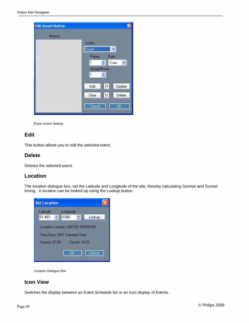
The location dialogue box, set the Latitude and Longitude of the site, thereby calculating Sunrise and Sunsettiming. A location can be looked up using the Lookup button.
Location Dialogue Box
Icon View
Switches the display between an Event Schedule list or an Icon display of Events.
Page 69
Vision Net Designer
© Philips 2009
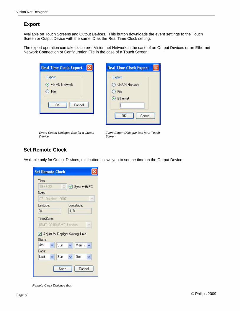
Export
Available on Touch Screens and Output Devices. This button downloads the event settings to the TouchScreen or Output Device with the same ID as the Real Time Clock setting.
The export operation can take place over Vision.net Network in the case of an Output Devices or an EthernetNetwork Connection or Configuration File in the case of a Touch Screen.
Event Export Dialogue Box for a OutputDevice
Event Export Dialogue Box for a TouchScreen
Set Remote Clock
Available only for Output Devices, this button allows you to set the time on the Output Device.
Remote Clock Dialogue Box

Page 70
Vision Net Designer
© Philips 2009

Page 71
Vision Net Designer
© Philips 2009

Page 72
Vision Net Designer
© Philips 2009
Push Button StationsPCB 70-1693 Rev A
J1 – Vision.net
1 Data + White/Orange
2 Data - Orange
3 SCREEN
4 +24v White/Green
5 GND Green
6 +24v White/Blue
7 GND Blue
8 +24v White/Brown
9 GND Brown

Page 73
Vision Net Designer
© Philips 2009
DMX Interface StationsPCB 70-1678 Rev B
J5 + J6 Vision.net
1 Data + White/Orange
2 Data - Orange
3 SCREEN
4 +24v White/Green
5 GND Green
6 +24v White/Blue
7 GND Blue
8 +24v White/Brown
9 GND Brown
J1 – DMX In
1 Screen
2 Data -
3 Data +
4 NC
5 NC
J2 – DMX Out
1 Screen
2 Data -
3 Data +

Page 74
Vision Net Designer
© Philips 2009
4 NC
5 NC
J4 – Power (12v -24v)
PinHole
+V
Barrel GND
Page 75
Vision Net Designer
© Philips 2009
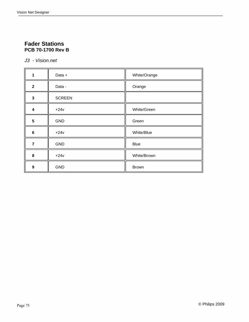
Fader StationsPCB 70-1700 Rev B
J3 - Vision.net
1 Data + White/Orange
2 Data - Orange
3 SCREEN
4 +24v White/Green
5 GND Green
6 +24v White/Blue
7 GND Blue
8 +24v White/Brown
9 GND Brown

Page 76
Vision Net Designer
© Philips 2009
RS232 Station
Vision.net
1 Data + White/Orange
2 Data - Orange
3 SCREEN
4 +24v White/Green
5 GND Green
6 +24v White/Blue
7 GND Blue
8 +24v White/Brown
9 GND Brown
Serial Port
Serial Ports Female 9 pin D-type
Pin Description
Pin 1 Data carrier detect
Pin 2 Receive data
Pin 3 Transmit data
Pin 4 Data terminal ready
Pin 5 Ground
Pin 6 Data set ready
Pin 7 Request to send
Pin 8 Clear to send

Page 77
Vision Net Designer
© Philips 2009
Pin 9 Ring indicator
General purpose RS232, baud rates 9600

Page 78
Vision Net Designer
© Philips 2009
Palette
Serial Port Male 9 pin D-type
1 Data carrier detect
2 Receive data
3 Transmit data
4 Data terminal ready
5 Ground
6 Data set ready
7 Request to send
8 Clear to send
9 Ring indicator
General purpose RS232, baud rates 1200 to 38400

Page 79
Vision Net Designer
© Philips 2009
Portable Stations and ScreensReceptacle Station
Female 6 pin XLR
1 Ground Green, Blue, Brown
2 +24V White/Green, White/Blue,White/Brown
3 Data - Orange
4 Data + White/Orange
5 TS VCommon
6 TS V+
Portable Station
Male 6 pin XLR
1 Ground
2 +24V
3 Data -
4 Data +
5 TS VCommon
6 TS V+

Page 80
Vision Net Designer
© Philips 2009

Page 81
Vision Net Designer
© Philips 2009
Button and Event Actions
Table of Button/Event Settings
Preset If the action is set as a Preset it will allow you to set which room and whichpreset the button selects. It will also allow you to set a fade time for thepreset. A preset selection button also has the option to disable the Pressand Hold Learn feature for the button
Applies to Touch Screens, Smart Buttons, Timed Events and ButtonStations
Preset On/Off If the action is set as a Preset On/Off the Button becomes a latchingbutton, switching the selected preset on and off.
Applies to Touch Screens, Smart Buttons and Button Stations
Toggle The toggle action will allow you to switch a channel belonging to a groupon and off with each press. You specify the ID of the Group the channelbelongs to and the number of the channel.
Tip: To toggle more than one circuit at the same time,you can either use the Preset On/Off button or aSmart Button as a latching button with a Toggle Onaction on the Button Down action and Toggle Offaction on the Button Up action.
Using Smart buttons like this, you can add a waittime between each circuit switching On/Off therebyobtaining a sequenced switch on/off of the circuits.
Applies to Touch Screens, Smart Buttons, Timed Events and ButtonStations
Smart As a Smart Button, you can fully customise the action of the button and theEdit button allows you to set the button action. Smart buttons can beeither latching momentary action switches, with actions assigned to eitherthe “Button Down” action (when the button is pressed) or the “Button Up”action (when the button is released).
The default action is placed on the Button Up Action.
Tip: Set the button to be a Latching button rather thenthe default Momentary action, when you are usingdifferent actions for the Button Down and Button Up
Note: So as to avoid conflicts, a Smart Button’scommands are only sent by Panels or Touchscreens, or on a virtual Touch Screen on a Vision.net Designer PC.

Page 82
Vision Net Designer
© Philips 2009
When using the Mimic style on Vision.net Designer,selecting a smart button on a mimicked touchscreen will still send the button Up/Down action,thereby triggering the real device to send the smartbutton commands.
Applies to Touch Screens, Smart Buttons and Button Stations
Lock Button The Lock button action allows you select the a button on a particular panelto be lock thereby preventing it from being pressed by a user. This can behandy for buttons in public areas, allowing them to only to be available atcertain times of day.
With the Button selection, you can select either all buttons or a just asingle button. Under Panel ID you enter the Number of the Panel you wantthe button(s) to be locked.
Note: To lock multiple buttons use multiple lock actions ona Smart button
Applies to Smart Buttons and Timed Events
Unlock Button Unlocking buttons allows you to select the button and the panel that youwish to allow to unlock.
With the Button selection, you can select either all buttons or a just asingle button.
Under Panel ID you enter the Number of the Panel you want the button(s)to be unlocked.
Note: To lock multiple buttons use multiple lock actions ona Smart button
Applies to Smart Buttons and Timed Events
Wait This function is a program flow control and allows you considerable controlover what the button does.
A wait allows you to put a pause in the actions of the smart button. Handyfor example if you want a button to Switch On a circuit and then a fewmoments later to switch on another.
Applies to Smart Buttons
Loop This function is a program flow control and allows you considerable controlover what the button does.

Page 83
Vision Net Designer
© Philips 2009
The Loop action allows you to loop to a specific action. A count allows youto specify the number of time that it will go through that loop.
Applies to Smart Buttons
Smart On This function allows you control other smart buttons on panels and switchthem on remotely.
Applies to Smart Buttons and Timed Events
Smart Off This function allows you control other smart buttons on panels and switchthem off remotely.
Applies to Smart Buttons and Timed Events
Raise A button configured as a Raise Button allows you to either RaiseChannels, a defined Preset or the currently selected Preset
Applies to Touch Screens and Button Stations
Lower A button configured as a Lower Button allows you to either lowerChannels, a defined Preset or the currently selected Preset.
Applies to Touch Screens and Button Stations
Genlyte Scene This function allows you control a Genlyte Controls ILS station connectedon the same network and select one of its presets.
Applies to Touch Screens, Smart Buttons, Timed Events and ButtonStations
Console Button This function allows you to trigger events on a Strand Lighting Palette,Light Palette or Rack Palette lighting control console.
For more detail on the setup for this see: Palette OS
Applies to Touch Screens, Smart Buttons, Timed Events and ButtonStations
Smart Mimic This allows this button to mimic the state of a button on a Touch Screen inthe network.
Applies to Touch Screens and Button Stations
Room Link This allows the button to act a Room Combine function, joining two Groupsor Rooms together.
Applies to Touch Screens and Button Stations
No Button On a button station, this option removes the button for configurationpurposes.
Page 84
Vision Net Designer
© Philips 2009
Applies to Button Stations
Select Mode This allows the button to select one of the 9 differnt modes of systemoperation.
Applies to Touch Screens, Smart Buttons, Timed Events and ButtonStations
Share Button This allows a shared Shared Button on a Touch screen to be remotelypressed.
Buttons that can be shared are PSSLS, Room Link, Smart Buttons, Tabsand Toggle Master buttons on a Touch Screen. Buttons on a TouchScreen as shared and given a name to identify it.
Applies to Touch Screens, Smart Buttons, Timed Events and ButtonStations
RTC Group Used in Smart buttons to enable or disable Real Time Clock Group Events
Applies to Smart Buttons and Timed Events
Toggle Master Toggle Masters allow Toggle Buttons Groups to be learned. This can bevery useful when using Toggle Buttons for Non-Dims on a Stage Lightingsystem.
Toggle Masters may be set to Perform in one of three ways:
1) Alternate Action where the Button alternately turns On and Off theselected Toggle Buttons
2) Toggle On where the Button turns On the selected Toggle Buttons
3) Toggle Off where the Button turns Off the selected Toggle Buttons
Applies to Touch Screens
Suspend Clock Having a Toggle Action, when active, this button suspends any pending Real Time Clock events on the designated clock controller.
Applies to Touch Screens,
Set Clock This button opens up the Clock dialog option of a touch screen.
Applies to Touch Screens,
CK Show This button type will trigger a Philips ColorKinetics Show state. Theconnection for the Philips ColorKinetics Show is configured in the TouchScreen Properties Dialogue
Applies to Touch Screens,
Sweep Room This Action will "Sweep Up" the lights in a room, placing the room in

Page 85
Vision Net Designer
© Philips 2009
darkness. The sweep action has two parameters, Warn and Shutofftimes.
When the Sweep action takes place, the lights in the designated room willbriefly flash to warn you that they will change, provided the "warn" option isselected for that circuit on the Ouput Device.
After the warn time, Preset 0 for that room will be selected.
If a new preset is selected after the warning, that preset will remain activefor the Shutoff time.
Example:
Sweep is set for 11:00PM
Warn is 5Shutoff is 60
11:00 pm Warning11:05 PM Off
A preset is pressed at 11:30
12:30 AM Warning12:35 AM Off
The sweep will remain active until an End Sweep Room event is activated.
Note: A Sweep Action will not clear any toggle buttons thatare currently on but will switch off those circuits. Consequentially you should not have any togglecontrollers in a room that will be swept.
Applies to Timed Events
End Sweep Room The End Sweep Room event cancels the Sweep Room Action.
Applies to Timed Events

Page 86
Vision Net Designer
© Philips 2009
Smart Buttons
Smart Buttons
Smart buttons are one of the most powerful features of VisionNet, allowing a number of actions to be combinedon the press of a single button.
These buttons have two actions, one while the button is held down and the other when the button is released.Additionally, smart buttons can be configured t have either a momentary or toggle action.
Note: Since Button Down actions only take place when the button is held down, it is often bestpractice; when using a momentary action on a smart button, to put all the actions in theButton Up list. By doing this, it removes the need for the user to hold the button downuntil all the events have processed.
Conversely, this can also be used to your advantage. If by introducing a Wait action on akey, you can ensure that an action on it takes place, only if a user "Holds" the buttondown for the duration of the Wait time.
Example
Smart Button Properties Dialog.
Using the Smart Button Dialog boxes, you can create sophisticated events. The above example shows aexample of a button which will perform as follows:
1. When the button is held down, it will trigger Preset 1 in Room/Group 2.
2. When the button is released, it will run Preset 1 in Room/Group 1, wait for an hour and then RunPreset 2 in Room/Group 1 continually cycling round 5 presets. This for example could be used tochange colours on a set of LED devices cycling round a sequence of colours.

Page 87
Vision Net Designer
© Philips 2009
Touch Screen Maintenance
Maintenance Mode
A special Maintenance Mode is provided for Touch Screens. In this mode, you can bring up settings on thetouchscreen, allowing them to be changed.
To enable the Maintenance Mode, hold down the Control key and select the desired touch screen from the MyNetwork Tree. If you are currently viwing the touchscreen you wish to maintain, then first select another itemfrom the Network Tree. A password prompt will appear. Enter the Password and a new toolbar option will beavailable.
Select Maintenance and the following dialogue box will appear
Select the required Option and follow the on screen instructions.

Page 88
Vision Net Designer
© Philips 2009
Trouble Shooting
In order to determine if a Vision.net Network device is communicating, a network test signal can be sent todevices on the network, using the Vision.net Designer software . To do this, the Flash Station signal is sent tothe station in order to verify communications.
Station Identification:Step 1. Connect the PC running the Vision.net Designer software to the Vision.net Network via
the Vision.netRS232 station, using an RS232 lead. Alternatively you can connect to theVision.net network using a Bluetooth interface. Please contact your local Strand LightingOffice for more details on this interface.
Step 2: Set Vision.net Designer to work “On Line”.
Step 3: Select the required panel from the Network Tree and press the Station ID button.
Step 4: Select Flash Station and the LED Indicators of the selected station will flash.
Using the Flash Station tool to troubleshoot.

Page 89
Vision Net Designer
© Philips 2009
Offices and Service Centres
Strand Lighting Asia,20/F Delta House, 3 On Yiu Street, Shatin, N.T. Hong Kong Tel: + 852 2757 3033 Fax: + 852 2757 1767
Strand Lighting Europe Ltd, Unit 2 Royce Road, Fleming Way, Crawley, West Sussex. United KingdomTel: + 44 1293 554010 Fax: + 44 1293 554019
Strand Lighting Inc, 6603 Darin Way, Cypress, CA 90630, USATel: +1 714 230 8200 Fax: +1 714 230 8173
The material in this manual is for information purposes only and is subject to change without notice. StrandLighting assumes no responsibility for any errors or omissions which may appear in this manual. For commentsand suggestions regarding corrections and/or updates to this manual, please contact your nearest StrandLighting office.
El contenido de este manual es solamente para información y está sujeto a cambios sin previo aviso. StrandLighting no asume responsabilidad por errores o omisiones que puedan aparecer. Cualquier comentario,sugerencia o corrección con respecto a este manual, favor de dirijirlo a la oficina de Strand Lighting máscercana.
Der Inhalt dieses Handbuches ist nur für Informationszwecke gedacht, Aenderungen sind vorbehalten. StrandLighting uebernimmt keine Verantwortung für Fehler oder Irrtuemer, die in diesem Handbuch auftreten. FürBemerkungen und Verbesserungsvorschlaege oder Vorschlaege in Bezug auf Korrekturen und/oderAktualisierungen in diesem Handbuch, moechten wir Sie bitten, Kontakt mit der naechsten Strand Lighting-Niederlassung aufzunehmen.
Le matériel décrit dans ce manuel est pour information seulement et est sujet à changements sans préavis. Lacompagnie Strand Lighting n'assume aucune responsabilité sur toute erreur ou omission inscrite dans cemanuel. Pour tous commentaires ou suggestions concernant des corrections et/ou les mises à jour de cemanuel, veuillez s'll vous plait contacter le bureau de Strand Lighting le plus proche.
Information contained in this document may not be duplicated in full or in part by any person without prior writtenapproval of Strand Lighting Inc. Its sole purpose is to provide the user with conceptual information on theequipment mentioned. The use of this document for all other purposes is specifically prohibited. Certainfeatures of the equipment described in this document may form the subject of patents or patent applications.

Page 90
Vision Net Designer
© Philips 2009
Index
- A -Adding Devices 58
- B -Button and Event Actions 81Button Stations 72Buttons 31
- C -Communications 9Control Stations 30Custom Panels 38
- D -DMX Interface 73
- F -Fader Stations 75File 12
- G -Group/Rooms 29
- H -Help 22
- L -Loading from a Station 37Loading Touchscreen 55
- M -Main Tool Bar 24Maps: Display/Unlock All 22Mode Maps 19
- O -Offices and Service Centres 89Operating Style 18Output Devices 57
- P -Palette 78Portable Stations and Screens 79

Page 91
Vision Net Designer
© Philips 2009
- R -Real Time Clock 66, 21RS232 Station 76
- S -Saving and Loading Station Configurations 35Saving to a Station 36Screen Design 43Setup 15Simulations 62Slider Faders 33Smart Buttons 86Station ID 34Status Bar 27
- T -Timed Events 67Tools 14Touch Screen Buttons 47Touch Screen Maintenance 87Touch Screen Raise and Lower 51Touch Screen Slider 48Touch Screen Slider Panels 50Touch Screen Tabbed Views 44Touch Screen Text 52Touch Screen Tool Bar 41Touch Screens 39Trouble Shooting 88
- V -Vision.Net Designer SoftwareVision.Net Overview 8
- W -Welcome , 6Welcome , 6

Page 92
Vision Net Designer
© Philips 2009

Strand Lighting Europe Limited, Unit 2 Royce Road, Fleming Way, Crawley, West Sussex. United Kingdom. RH10 9JY Tel: + 44 1293 554 010 Fax: + 44 1293 554 019 Strand Lighting Asia, 20/F Delta House, 3 On Yiu Street, Shatin, N.T. Hong Kong Tel: + 852 2757 3033 Fax: + 852 2757 1767 Strand Lighting Inc, 6603 Darin Way, Cypress, CA 90630, USA Tel: +1 714 230 8200 Fax: +1 714 230 8173 © 2009 Philips Group. All Rights Reserved.


![BlipNet API Jan Justesen Software Designer [jan.justesen@blipsystems.com]](https://img.dokumen.tips/doc/110x75/56649d625503460f94a44bda/blipnet-api-jan-justesen-software-designer-janjustesenblipsystemscom.jpg)