Embed Size (px)
Citation preview
7/17/2019 Design_and_Implementation_of_a_Feasible_Microgrid_Model_in_Brazil_full.pdf
http://slidepdf.com/reader/full/designandimplementationofafeasiblemicrogridmodelinbrazilfullpdf 1/9
See discussions, stats, and author profiles for this publication at: http://www.researchgate.net/publication/268801009
Design and Implementation of a FeasibleMicrogrid Model in Brazil
CONFERENCE PAPER · OCTOBER 2014
READS
33
1 AUTHOR:
Marcos Aurelio Izumida Martins
Federal University of Santa Catarina
5 PUBLICATIONS 0 CITATIONS
SEE PROFILE
Available from: Marcos Aurelio Izumida Martins
Retrieved on: 25 September 2015
7/17/2019 Design_and_Implementation_of_a_Feasible_Microgrid_Model_in_Brazil_full.pdf
http://slidepdf.com/reader/full/designandimplementationofafeasiblemicrogridmodelinbrazilfullpdf 2/9
Design and Implementation of a Feasible Microgrid Model in
Brazil
Felipe Cassias, Celesc S.A., Avenida Itamarati, Brazil, [email protected] Pica, Fundação CERTI, Campus da UFSC, Setor C, Brazil, [email protected] Izumida, Fundação CERTI, Campus da UFSC, Setor C, Brazil, [email protected] Gentilini, Fundação CERTI, Campus da UFSC, Setor C, Brazil, [email protected] Maryama, Fundação CERTI, Campus da UFSC, Setor C, Brazil, [email protected] Makohin, Fundação CERTI, Campus da UFSC, Setor C, Brazil, [email protected]
The Power Point Presentation will be available after the conference.
Abstract
This paper aims to present the topology and energy management solutions implemented in a20kW microgrid project in Brazil, integrating renewable resources, backup power, controllableloads and the main grid. The objective of this project has been to develop a microgrid modelfor neighborhood/district application that may become feasible in the short term. This microgridproject has been designed using control techniques that allow it to operate in grid-connectedand island mode and to participate in Virtual Power Plant schemes. Preliminary results haveshown feasibility of the project, which should guide local utilities regarding the adoption ofmicrogrid technologies.
1. Introduction
In order to promote the deployment of small-scale distributed generation (DG), in 2012, theBrazilian Agency of Electric Energy (ANEEL) approved the Net Metering act [1], allowingbidirectional energy flow between consumers/producers and the main grid. Due to this act,along with a steady decline in the prices of DG, a massive connection of small-scale DG to themain grid is expected in the near future. On the one hand, this picture is very motivating,however this sudden allowance of small-scale DG may escape beyond the control of theutilities and distribution operators, bringing new concerns such as impacts in power quality andcommercial issues between utilities and prosumers. A promising solution to these concerns arises with the concept of microgrids [2] [3]. In this
context, the objective of the work presented in this paper is to develop, implement and evaluatea feasible microgrid model, helping power utilities to understand better the availabletechnologies and solutions for this kind of system and their impact and benefits for the wholepower grid. In this work, a 20kW pilot microgrid project has been designed and implemented,establishing a test bed where DG technologies, power quality solutions, control strategiessystems, islanded operation, etc. could be tested and validated from the utilities’ point of view.Firstly, the paper shows the topology design and energy management system adopted and,then, simulation and preliminary experimental results are presented.

7/17/2019 Design_and_Implementation_of_a_Feasible_Microgrid_Model_in_Brazil_full.pdf
http://slidepdf.com/reader/full/designandimplementationofafeasiblemicrogridmodelinbrazilfullpdf 3/9
2. The Pilot Microgrid
2.1. Topology
The pilot microgrid, named District Power Plant, has a radial topology for electricity distribution,mirroring the most common distribution nets present around the country. The core of the
system is the Multicluster Box 6, a metering/switch panel with the capability to act under thecontrol of the Sunny Island inverters for operations like resynchronization, islanding andprotection.On the connection side, there is an automatic transfer switch (ATS) responsible for switch tothe diesel generator when the main grid suffers a fault event; although it does not activate thegenerator automatically, (the supervisory system starts the generator).Deeper into the system, there is a generation branch for photovoltaic (PV) and wind power, aload branch for alternate current (AC) loads and a storage branch where three inverters workas an interface between the AC bus and the direct current (DC) bus for batteries and load.
Figure 1 - Simplified topology
Figure 2 - Wind generation unit and the photovoltaic panels
7/17/2019 Design_and_Implementation_of_a_Feasible_Microgrid_Model_in_Brazil_full.pdf
http://slidepdf.com/reader/full/designandimplementationofafeasiblemicrogridmodelinbrazilfullpdf 4/9
2.2. Generation Units
Three power sources fall under the class of generation units: photovoltaic (PV), wind and dieselgeneration, which totalize 13.6kVA of installed capacity. Out of this amount, 5.5kVA are usedonly in case of islanded operation, as the diesel generator is not allowed to work underconnected mode because of the ATS mutual exclusion and it is intended for the diesel
generator to only server as a battery charger.The 8.1kVA remaining generation belongs to the wind power generation (2.4kVA) and PVgeneration (5.7kVA). These two sources help mitigate the power drained from the utility duringconnected mode, or even feeding the utility when the loads are not at full capacity. Duringislanded operation, it helps the battery to feed the loads or even feed the loads alone insituations of high power generation und low load usage.
2.3. Storage
Four 12V serial connected lead-acid batteries compose energy storage of the microgrid. Asthey have a DC connection, there was a need for a DC bus of 48V that is connected to the
three battery inverters because of the inverters operational parameters. Each of the invertersis responsible for one phase of the AC side. Because of the three inverters used, it is possiblefor them to balance the phases of the system by using the DC bus.In terms of capacity, the battery bank is able to yield 220Ah to the DC bus for 10,6kW of powerduring an hour (10,6kWh of energy), but to avoid deep discharges that damage or reduce thebatteries’ life time, the research team placed limits for the discharge/recharge times andcurrent. The maximum current can only operate for 15 minutes while the minimum capacityallowed is 30%, when operating in islanded mode. For connected mode, unless there is adispatch order made by the supervisory system, the batteries stay almost fully charged (around90%) in order to absorb energy from the renewable sources in case of change to islandedmode.
2.4. Consumption
There are two kind of load fed by the district power plant: AC loads and a DC load. Four loadsare connected to the AC load branch of the multicluster box while one load gets power fromthe DC bus. The loads are all controllable by the supervisory system that may turn them offwhen there is need for power under islanded mode or when it is economically feasible to sendenergy to the utility. The four AC loads are comprised of two resistor banks of 4.5kVA each(both of low priority), the cooling system of 1.6kVA (highest priority) and 1.9kVA of illumination(high priority). The sole DC load is a resistor bank of 2.5kW (low priority).
3. Dispatch Simulation
Before finishing the executive project of the microgrid, the research team simulated severalscenarios to attest the feasibility of the project. These simulations were made in a softwarebuilt by the research team itself and the data for wind and PV power were obtained from aweather station at the site of the microgrid for one year. The Figure 3, Figure 4 and Figure 5show the curves used for the simulation of load profile and renewable generation. The powersources and storage present in the section 2 are also present in this simulation. For the loads,scenarios of 5, 10 and 20kW were tested. The simulations are valid only for active power.

7/17/2019 Design_and_Implementation_of_a_Feasible_Microgrid_Model_in_Brazil_full.pdf
http://slidepdf.com/reader/full/designandimplementationofafeasiblemicrogridmodelinbrazilfullpdf 5/9
Figure 3 - Typical commercial demand curve
Figure 4 – typical wind speed for a week
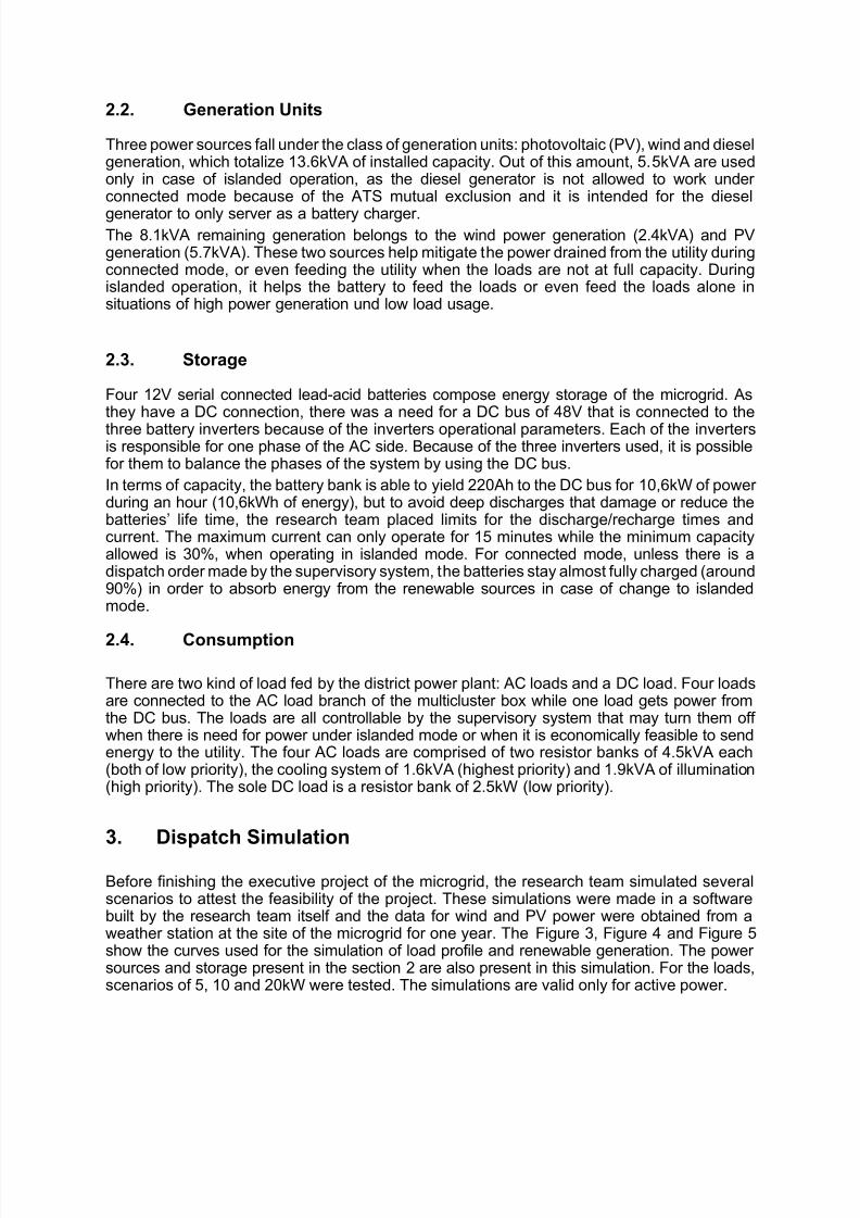
3.1. Operation under connected mode
While operating under connected mode, the batteries and the diesel generator play no activerole, as the main grid feeds the loads with the necessary amount of power. This leaves the PV
and wind generation as the power source from the microgrid side. Scenarios of 5, 10 and 20kW of peak load were tested and they resulted in 7.77MWh of energy consumption and2.23MWh of energy exportation for the 5kW load scenario, 19MWh and 1.53MWh for the 10kWload scenario, and 31.58MWh and 1.14MWh for the 20kW load scenario. The Figure 6 showsthe power flow between utility and microgrid when operating with 10kW of peak load.
Figure 5 - typical solar irradiation for a week
7/17/2019 Design_and_Implementation_of_a_Feasible_Microgrid_Model_in_Brazil_full.pdf
http://slidepdf.com/reader/full/designandimplementationofafeasiblemicrogridmodelinbrazilfullpdf 6/9
Figure 6 - Power flow between microgrid and utility during two weeks under connected mode at 10kW of peak
load
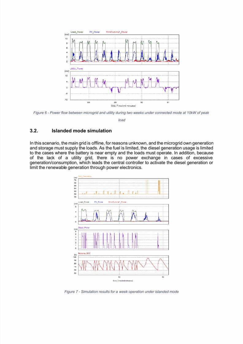
3.2. Islanded mode simulation
In this scenario, the main grid is offline, for reasons unknown, and the microgrid own generationand storage must supply the loads. As the fuel is limited, the diesel generation usage is limitedto the cases where the battery is near empty and the loads must operate. In addition, becauseof the lack of a utility grid, there is no power exchange in cases of excessivegeneration/consumption, which leads the central controller to activate the diesel generation orlimit the renewable generation through power electronics.
Figure 7 - Simulation results for a week operation under islanded mode
7/17/2019 Design_and_Implementation_of_a_Feasible_Microgrid_Model_in_Brazil_full.pdf
http://slidepdf.com/reader/full/designandimplementationofafeasiblemicrogridmodelinbrazilfullpdf 7/9
The battery inverters together with the central controller control the diesel generation dispatchaccording to the battery charge level. When the charge level of the battery reaches a pre-established level, the control system activates the diesel generation, unless a load sheddingstrategy is running. The diesel generation then works until the battery is fully charged. For thiscontrol strategy, the boundaries for charge and discharge are 90 % and 60 % of the batterylevel to avoid deep discharges, which compromises the batteries, as well as to allow someenergy absorption when there is excessive renewable generation. Figure 7 shows an exampleof operation under islanded mode for a load profile of 5kW of peak load.
4. Microgrid Automation and Control
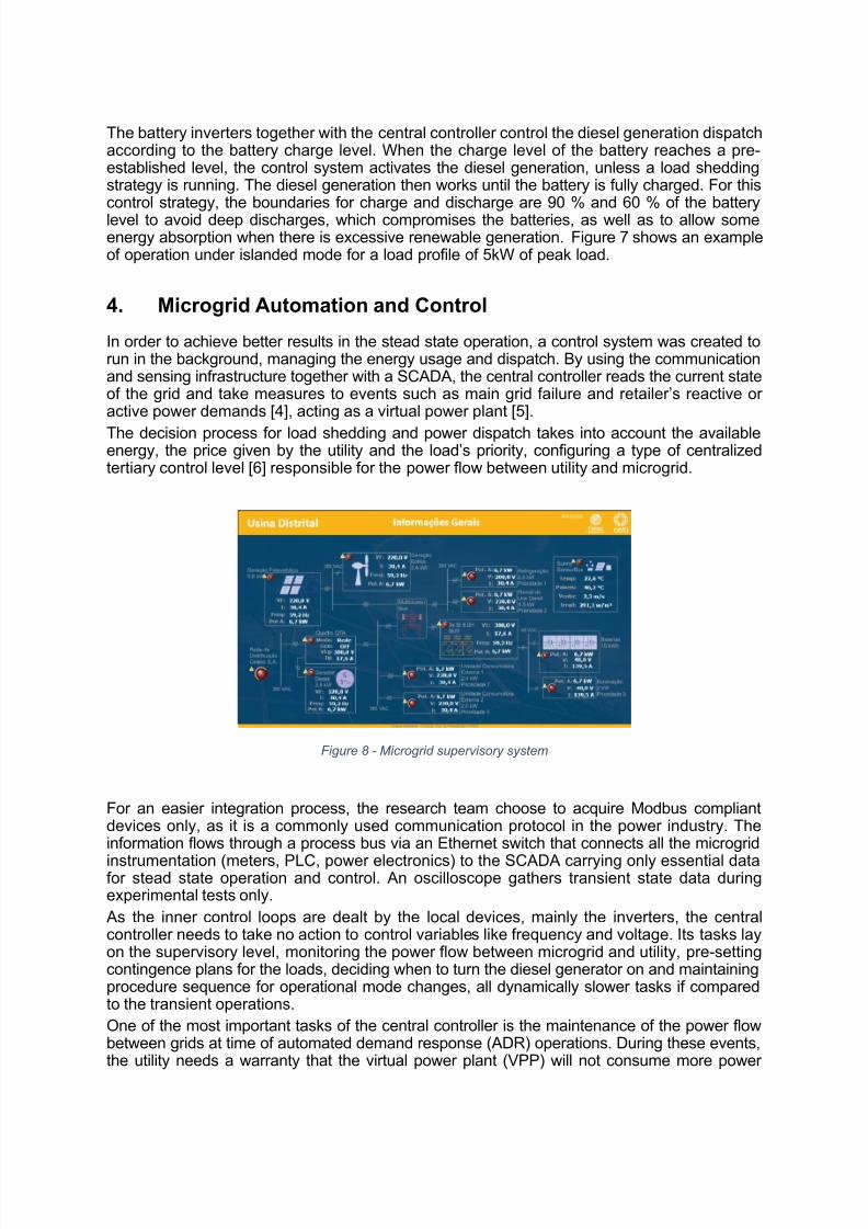
In order to achieve better results in the stead state operation, a control system was created torun in the background, managing the energy usage and dispatch. By using the communicationand sensing infrastructure together with a SCADA, the central controller reads the current stateof the grid and take measures to events such as main grid failure and retailer’s reactive oractive power demands [4], acting as a virtual power plant [5].
The decision process for load shedding and power dispatch takes into account the availableenergy, the price given by the utility and the load’s priority, configuring a type of centralizedtertiary control level [6] responsible for the power flow between utility and microgrid.
Figure 8 - Microgrid supervisory system
For an easier integration process, the research team choose to acquire Modbus compliantdevices only, as it is a commonly used communication protocol in the power industry. Theinformation flows through a process bus via an Ethernet switch that connects all the microgrid
instrumentation (meters, PLC, power electronics) to the SCADA carrying only essential datafor stead state operation and control. An oscilloscope gathers transient state data duringexperimental tests only. As the inner control loops are dealt by the local devices, mainly the inverters, the centralcontroller needs to take no action to control variables like frequency and voltage. Its tasks layon the supervisory level, monitoring the power flow between microgrid and utility, pre-settingcontingence plans for the loads, deciding when to turn the diesel generator on and maintainingprocedure sequence for operational mode changes, all dynamically slower tasks if comparedto the transient operations.One of the most important tasks of the central controller is the maintenance of the power flowbetween grids at time of automated demand response (ADR) operations. During these events,the utility needs a warranty that the virtual power plant (VPP) will not consume more power
7/17/2019 Design_and_Implementation_of_a_Feasible_Microgrid_Model_in_Brazil_full.pdf
http://slidepdf.com/reader/full/designandimplementationofafeasiblemicrogridmodelinbrazilfullpdf 8/9
than what was accorded between the two parts (feeding less power than it was accorded alsofalls under this consideration). The equation 1, where P_Load stands for the internalconsumption, P_Gen stands for internal generation and Putility stands for the accorded ADRpower plus 10% of hysteresis for safety purposes as seen in [7]. Therefore, the SCADA isprogrammed to measure the available power and the consumption and to give a dispatch orderto the battery or a disconnection order to any internal load should the equation 1 become
unbalanced.
∑ ∑ _
=+ ∑_
=+ 0 (1)
The central controller is also responsible to set a price for an ADR action. It solves theoptimization problem of the equation 2, minimizing the energy cost on the microgrid side FC infunction of the active power. The model used for optimization takes the generation forecastand price for the renewable sources as well as the cost to turn the loads off or to dispatch thebatteries. The result is an optimal price for multiple ADR scenarios. Each ADR event lasts onlyfor 15 minutes because demand response operations are short term actions for balance in the
utility side as it can be treated as an ancillary service [8].
() ∑(( ) + )=
=1⏟
+ ∑ ( ( ) + )=
=1⏟−ℎ
() ± ()⏟
(2)
5. Conclusion
This work leads the research team to conclude that microgrids are feasible in the short termeven in countries under development like Brazil regarding technical issues, although these
technologies are not as available as it is in economically developed countries, which make theprocess of building slower and more expensive as it was expected. As of the end of this paper, the whole system installation and commissioning is at its end. Inaddition, the individual tests of the devices shows that they are able to follow the local rules forelectrical operation. Preliminary tests of the devices working as an integrated system are aboutto be started and experimental results of the operational modes are expected to be obtainedvery soon.The next steps regarding this system are the tests for full compliance of the system ’soperational modes according to national laws of the energy sector, the creation of an interfacefor interaction between the utility and the microgrid and the development of an economicallyfeasible business model that brings benefits for both utility and costumer.
6. References
[1] AGÊNCIA NACIONAL DE ENERGIA ELÉTRICA – ANEEL, "RESOLUÇÃO NORMATIVANº 482," 2012.
[2] N. Hatziargyriou, H. Asano, R. Iravani and C. Marnay, "Microgrids," 2007.
[3] S. Chowdhury, S. Chowdhury and P. Crossley, "Microgrids and Active DistributionNetworks," 2009.
[4] H. Nunna and S. Doolla, "Intelligent demand side management in smart-microgrids," 2013.

7/17/2019 Design_and_Implementation_of_a_Feasible_Microgrid_Model_in_Brazil_full.pdf
http://slidepdf.com/reader/full/designandimplementationofafeasiblemicrogridmodelinbrazilfullpdf 9/9
[5] L. Toma, B. Otomega, C. Bulac and I. Tristiu, "Coordination of Distributed GeneratorsThrough the Virtual Power Plant Concept," 2012.
[6] J. M. Guerrero, J. C. Vásquez and R. Teodorescu, "Hierarchical Control of Droop-Controlled DC and AC Microgrids - A General Approach Towards Standardization,"Industrial Electronics, 2009. IECON '09. 35th Annual Conference of IEEE, Novembro
2011.[7] I. PVPS, "The role of energy storage for mini-grid stabilization," 2011.
[8] U. D. o. Energy, "Benefits of Demand Response in Electricity Markets andRecommendations for Achieving Them," 2006.


