Embed Size (px)
Citation preview

BULLETIN 327
Design Suggestions and Greenhouse Management for Vegetable Production in Perlite and Rockwool Media in Florida1
George Hochmuth and Robert Hochmuth2
1. This document is BULLETIN 327, one of a series of the Horticultural Sciences Department, UF/IFAS Extension. This document is BULLETIN 327, one of a series of the Horticultural Sciences Department, UF/IFAS Extension. First published as SSVEC-44 in October, 1990. Reprinted as SP110 in June, 1992; September, 1994; and October 1997. Revised and reprinted as Bulletin 327 in February 1998. Updated February 2004. Reviewed March 2015. Visit the EDIS website at http://edis.ifas.ufl.edu. Visit the EDIS website at http://edis.ifas.ufl.edu.
2. George J. Hochmuth, professor emeritus, Soil and Water Science Department; and Robert C. Hochmuth, regional specialized Extension agent IV, North Florida Research and Education Center - Suwannee Valley, Live Oak, FL; UF/IFAS Extension, Gainesville, FL 32611.
The Institute of Food and Agricultural Sciences (IFAS) is an Equal Opportunity Institution authorized to provide research, educational information and other services only to individuals and institutions that function with non-discrimination with respect to race, creed, color, religion, age, disability, sex, sexual orientation, marital status, national origin, political opinions or affiliations. For more information on obtaining other UF/IFAS Extension publications, contact your county’s UF/IFAS Extension office.
U.S. Department of Agriculture, UF/IFAS Extension Service, University of Florida, IFAS, Florida A & M University Cooperative Extension Program, and Boards of County Commissioners Cooperating. Nick T. Place, dean for UF/IFAS Extension.
The purpose of this publication is to present suggestions and options for designing and operating a greenhouse for vegetable production in perlite or rockwool. Suggestions are presented for growers who desire to change their NFT-pipe house over to solid media such as perlite or rockwool media. These recommendations also would apply to other media, such as peat or pine park mixes. The major con-siderations are those pertaining to the floor design for the media system. Suggestions also are presented for general greenhouse design and operation for tomato culture. Many of these suggestions would apply to houses with other production systems, e.g., upright bag or trough, and in most cases would be applicable for cucumbers, eggplant, and pepper. Additional details on crop culture (irrigation, fertilization, disease and insect control, etc.) can be found at the Florida Greenhouse Vegetable Production Handbook located at the UF/IFAS North Florida Research and Education Center website http://nfrec.ifas.ufl.edu/index.shtml [September 2011] or the UF/IFAS EDIS Publications website http://edis.ifas.ufl.edu/TOPIC_BOOK_Florida_Greenhouse_Vegetable_Production_Handbook.
IntroductionProduction of greenhouse vegetables using rockwool and perlite substrates is becoming standard practice in many
areas of North America (Figure 1). Rockwool is a solid growing medium made of rock fibers (usually basalt). The rock is melted and spun into fibers which are used to make loose “flock” or formed slabs (Figure 2). Fiber binding and wetting agents are added to provide the structure and moisture retention attributes necessary for horticultural use. Perlite is a volcanic mineral which, when heated, expands (pops like popcorn) into small, white particles (Figure 2). Perlite is placed in polyethylene growing bags approximately 36 inches long and 6 inches in diameter containing about 0.5 cubic ft. of perlite.
Figure 1. Tomatoes growing in perlite-filled lay-flat bags in a greenhouse in northern Florida.

2Design Suggestions and Greenhouse Management for Vegetable Production in Perlite and Rockwool ...
Rockwool and perlite provide for a high degree of capillary movement of water and have a large proportion of air space. New rockwool and perlite are pathogen-free and do not themselves provide nutrients to the crop. These media function as support for roots and hold nutrients in the solution around the roots.
Rockwool slabs and perlite bags can be reused if sterilized by steaming or other legal means. Costs to reuse the media (including labor, equipment rental, new poly sleeves, etc.) will run about one dollar per slab or bag. Research in northern states has shown that reuse for more than one additional year is possible but not recommended due to potential variability among slabs or bags for water conduc-tance and aeration. Extra handling of slabs damages and compresses the rockwool structure. Reuse of unsterilized media of any type in Florida is risky.
Rockwool and perlite have major advantages in Florida over the PVC pipe nutrient film technique (NFT) because rockwool and perlite are not recirculating-type production systems. Plants are isolated to individual rockwool slabs or bags of perlite and the nutrient solution is applied to each container individually. As a result, nutrient solution that might be contaminated with Pythium spores is not circulated throughout the greenhouse as in NFT (Figure 3). Aeration of root systems also is better in rockwool or perlite compared to the root systems in the modified NFT (PVC tube) system. The result with perlite or rockwool is a cultural system that is less risky from a root disease standpoint compared to the closed NFT pipe system.
The major design challenge in rockwool or perlite culture has to do with the design of the floor of the house to facilitate collection and removal of excess nutrient solution leachate from the media containers. It is not desirable, from
an environmental pollution standpoint, to allow the leach-ate to pass into the soil beneath the greenhouse.
Research has been conducted with perlite and rockwool for Florida. Suggestions for use of these media have been developed from experience and research in Florida and from research in other states and countries.
Site PreparationSite selection for greenhouses should be given much consideration for drainage, flooding probabilities, water supplies and quality, shading from trees, etc. The green-house site should be raised above the surrounding grade to facilitate quick drainage of water due to heavy rainfall from thunderstorms or hurricanes. More information is avail-able from the Florida Greenhouse Vegetable Production Handbook, Volume II.
The GreenhouseGreenhouse structures are available in many sizes, styles, and quality levels (Figure 4, Figure 5). For cooling efficien-cies, it is suggested that the greenhouse be no more than about 110 to 120 feet in length. Houses longer than this present problems in achieving uniform temperatures over the entire length of the house when cooling in early fall and late spring. The width for a single unit should be about 35 feet. This width allows for establishment of six twin-rows of tomatoes within the house and provides for open alleys around the inside perimeter of about 4 to 5 feet. These alleys provide space for air movement and for easy access to the crop for harvesting and spraying. A house 35×120 feet provides growing space for about 1100 tomato plants.
The house should have straight side walls at least four feet high, preferably eight feet. Side walls of eight feet are ideal if expansion to a multi-bay house is envisioned. Overall
Figure 2. Various media can be successfully used for greenhouse vegetable production in Florida.
Figure 3. Plants lost to pithium root rot in a recirculated NFT house in northern Florida.

3Design Suggestions and Greenhouse Management for Vegetable Production in Perlite and Rockwool ...
greenhouse height (ground to arch peak) need not to be more than 14 to 16 feet. Otherwise an excess volume of air will need to be heated or exhausted which increases operational costs.
Structural components for the house (sidewall columns, arches, bows, purlins, endwalls, etc.) can be home fabri-cated or purchased as a kit. Either way, the strength and quality of the components must be kept in mind. Saving money on less costly components could cost the grower in the long run if a house must be replaced or requires in-creased maintenance. If a homemade house is planned, the pipe needs to be of greenhouse structural grade, and a high quality pipe bending machine will be required. Pipework should be galvanized steel with a high yield and tensile strength of about 50,000 PSI. Sidewall columns should be about 2.5 inches outer diameter and arches should be about 1.6 to 1.9 inches outer diameter. Sidewall columns should be on 5- to 6-foot spacing and be anchored in concrete to a depth of at least 24 inches.
Cooling Pad EndwallEndwalls should be fabricated from galvanized pipe which is about 1.6 to 1.9 inches outer diameter. Pipe provides
more strength and life compared to wooden endwalls fabricated from 2×4 lumber. The cooling pad endwall consists of upright galvanized pipe on 5- or 6-foot centers anchored in the ground in concrete and attached at the top to the end arch. Cross members should consist of additional pipe or aluminum strips. Aluminum pieces are easier than galvanized pipe to drill when attaching the endwall sheet-ing. The pad endwall shown (Figure 6) has three framed openings. One opening is for the cooling pad and accom-modates the 6×30-foot cooling pad. The bottom of the pad frame should be about 12 to 15 inches off the ground. The pad opening should be framed with aluminum poly locking extrusion so that a piece of poly can be placed over the pad opening to close off the opening during winter, unless the
pad is equipped with a motorized shutter cover.
The other two suggested framed openings are each for 42-inch motorized inlet shutters (Figure 6, Figure 7). These aluminum shutters are recommended for use in the winter ventilation mode through which outside air can be drawn to cool the house. In this way, cool air is not drawn through the pad directly onto the plants at the end of the house. These shutters are closed in the summer when evaporative cooling via the pad is required. Each shutter is operated by an electric motor. Extra motors should be on hand for fast replacement of nonfunctioning motors. Each shutter is controlled by its own thermostat, or they can be wired so the shutters open simultaneously. It is a good idea to place each shutter on a separate thermostat or to wire the shutters through two thermostats because there is less chance of shutter opening failure. Shutters should be set to open one or two degrees ahead of the start-up of the first exhaust fan. For example, set the shutters to open at 75°F and the
Figure 4. Small single-unit greenhouse.
Figure 5. Multi-unit gereenhouse.
Figure 6. Cooling-pad endwall with open area for evaporative pad (in this photo, covered with motorized shutter) and 2 openings for motorizd shutters, above cooling pad.

4Design Suggestions and Greenhouse Management for Vegetable Production in Perlite and Rockwool ...
first exhaust fan at 78°F. These settings will ensure that the shutters are open before the fans start up.
Both cooling pad and shutters should have plastic screen or an insect cloth placed over the openings to help prevent insects from being drawn into the house. Screening will exclude larger insects such as moths, bugs, and grasshop-pers. However, most screens will not exclude small insects such as thrips. There is very little one can do to completely screen out these tiny insects without reducing the flow of air through the pad or shutter. If insect exclusion fabric is to be used to cover the pad, the air flow will be reduced. An alternative would be to construct a box frame over the pad area through which to draw air. This increases the surface area to draw air through.
Evaporative Cooling PadIn Florida, extra cooling is needed in fall and spring over and above that achieved solely by ventilation. Drawing air through evaporation pads provides an additional few degrees of cooling which is important for optimizing tomato production in hot weather conditions. More cooling is achieved in low humidity conditions; less to none under high humidity. The standard method for evaporative cool-ing is with a cellulose pad system (Figure 8). For tomatoes, the pad should be 6 feet high, at least 4 inches thick, and span nearly the entire width of the house. The bottom edge of the pad should be about 12 inches off the ground or floor of the house to reduce potential for soil and debris to enter the pad.
Most evaporative cooling pad systems come with complete instructions for proper installation and care of the pad. The sump tank should be sized to provide 3/4 gallon of water per square foot of pad area. Therefore, a 6×30-foot pad
needs a tank with a 130- to 160-gallon capacity. A concrete septic tank or a heavy-wall polyethylene tank are suitable for use as a sump tank. The tank needs to be buried outside the endwall of the house so that the opening to the tank is below the level of the return trough from the evaporative pad. The sump pump should be able to deliver at least ½ gallon water per linear foot of pad per minute. For the 6×30-foot pad, the pump must deliver 15 gallons per minute or 900 gallons per hour.
The evaporation process in the pad uses a considerable amount of water. Therefore, the water in the sump tank must be continually replenished. To achieve this, a float valve should be installed in the sump and attached to a ½-inch (or larger) supply line or tubing that can supply wa-ter to the valve as needed. This line can be installed under the floor of the house at the time the floor is installed.
Algae will be a problem on the pad surfaces. Therefore the sump tank needs to be covered to prevent light from reaching the water. Other helpful precautions are to treat the recirculating water with an approved algicide and to flush the tank periodically.
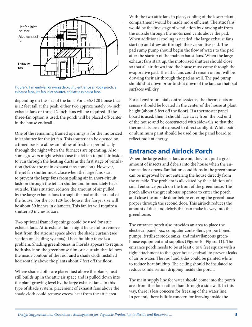
The Fan EndwallThe fan endwall of the house contains the exhaust fans, inlet shutter for the jet fan, and the entrance airlock porch (Figure 9). The fan endwall should be constructed with galvanized pipe uprights and aluminum or galvanized cross frame members. The fan endwall members support consid-erable weight, so care must be taken to build with strength and stability in mind. The framed openings include one for a 42-inch entrance door that will be the entrance to the greenhouse proper from the porch. Other framed openings are for the large exhaust fans. Two or three will be needed
Figure 7. Inside photo of motorized shutters covered with insect exclusion fabric.
Figure 8. Evaporative cooling pad with underground water return system.
5Design Suggestions and Greenhouse Management for Vegetable Production in Perlite and Rockwool ...
depending on the size of the fans. For a 35×120 house that is 12 feet tall at the peak, either two approximately 54-inch exhaust fans or three 42-inch fans will be required. If the three-fan option is used, the porch will be placed off-center in the house endwall.
One of the remaining framed openings is for the motorized inlet shutter for the jet fan. This shutter can be opened on a timed basis to allow an inflow of fresh air periodically through the night when the furnaces are operating. Also, some growers might wish to use the jet fan to pull air inside to run through the heating ducts as the first stage of ventila-tion (before the main exhaust fans come on). However, the jet fan shutter must close when the large fans start to prevent the large fans from pulling air in short-circuit fashion through the jet fan shutter and immediately back outside. This situation reduces the amount of air pulled by the large exhaust fans through the pad at the far end of the house. For the 35×120-foot house, the fan jet size will be about 30 inches in diameter. This fan jet will require a shutter 30 inches square.
Two optional framed openings could be used for attic exhaust fans. Attic exhaust fans might be useful to remove heat from the attic air space above the shade curtain (see section on shading systems) if heat buildup there is a problem. Shading greenhouses in Florida appears to require both shade on the greenhouse film or a curtain that follows the inside contour of the roof and a shade cloth installed horizontally above the plants about 7 feet off the floor.
Where shade cloths are placed just above the plants, heat still builds up in the attic air space and is pulled down into the plant growing level by the large exhaust fans. In this type of shade system, placement of exhaust fans above the shade cloth could remove excess heat from the attic area.
With the two attic fans in place, cooling of the lower plant compartment would be made more efficient. The attic fans would be the first stage of ventilation by drawing air from the outside through the motorized vents above the pad. When additional cooling is needed, the large exhaust fans start up and draw air through the evaporative pad. The pad sump pump should begin the flow of water to the pad after the startup of the main exhaust fans. When the large exhaust fans start up, the motorized shutters should close so that all air drawn into the house must come through the evaporative pad. The attic fans could remain on but will be drawing their air through the pad as well. The pad pump should shut down prior to shut down of the fans so that pad surfaces will dry.
For all environmental control systems, the thermostats or sensors should be located in the center of the house at plant height (about 5 feet off the floor). If a thermostat panel board is used, then it should face away from the pad end of the house and be constructed with sidewalls so that the thermostats are not exposed to direct sunlight. White paint or aluminum paint should be used on the panel board to reflect radiant energy.
Entrance and Airlock PorchWhen the large exhaust fans are on, they can pull a great amount of insects and debris into the house when the en-trance door opens. Sanitation conditions in the greenhouse can be improved by not entering the house directly from the outside. The problem is alleviated by the addition of a small entrance porch on the front of the greenhouse. The porch allows the greenhouse operator to enter the porch and close the outside door before entering the greenhouse proper through the second door. This airlock reduces the amount of dust and debris that can make its way into the greenhouse.
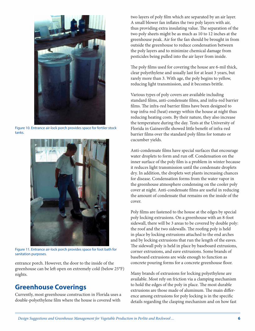
The entrance porch also provides an area to place the electrical panel box, computer controllers, proportioned pumps, fertilizer stock tanks, and miscellaneous green-house equipment and supplies (Figure 10, Figure 11). The entrance porch needs to be at least 6 to 8 feet square with a tight attachment to the greenhouse endwall to prevent leaks of air or water. The roof and sides could be painted white to reduce heat buildup. The ceiling should be insulated to reduce condensation dripping inside the porch.
The main supply line for water should come into the porch area from the floor rather than through a side wall. In this way, there is less concern for freezing of the water line. In general, there is little concern for freezing inside the
Figure 9. Fan endwall drawing depicting entrance air-lock porch, 2 exhaust fans, jet-fan inlet shutter, and attic exhaust fans.
6Design Suggestions and Greenhouse Management for Vegetable Production in Perlite and Rockwool ...
entrance porch. However, the door to the inside of the greenhouse can be left open on extremely cold (below 25°F) nights.
Greenhouse CoveringsCurrently, most greenhouse construction in Florida uses a double-polyethylene film where the house is covered with
two layers of poly film which are separated by an air layer. A small blower fan inflates the two poly layers with air, thus providing extra insulating value. The separation of the two poly sheets might be as much as 10 to 12 inches at the greenhouse peak. Air for the fan should be brought in from outside the greenhouse to reduce condensation between the poly layers and to minimize chemical damage from pesticides being pulled into the air layer from inside.
The poly films used for covering the house are 6-mil thick, clear polyethylene and usually last for at least 3 years, but rarely more than 3. With age, the poly begins to yellow, reducing light transmission, and it becomes brittle.
Various types of poly covers are available including standard films, anti-condensate films, and infra-red barrier films. The infra-red barrier films have been designed to trap infra-red (heat) energy within the house at night thus reducing heating costs. By their nature, they also increase the temperature during the day. Tests at the University of Florida in Gainesville showed little benefit of infra-red barrier films over the standard poly films for tomato or cucumber yields.
Anti-condensate films have special surfaces that encourage water droplets to form and run off. Condensation on the inner surface of the poly film is a problem in winter because it reduces light transmission until the condensate droplets dry. In addition, the droplets wet plants increasing chances for disease. Condensation forms from the water vapor in the greenhouse atmosphere condensing on the cooler poly cover at night. Anti-condensate films are useful in reducing the amount of condensate that remains on the inside of the cover.
Poly films are fastened to the house at the edges by special poly locking extrusions. On a greenhouse with an 8-foot sidewall, there will be 3 areas to be covered by double poly: the roof and the two sidewalls. The roofing poly is held in place by locking extrusions attached to the end arches and by locking extrusions that run the length of the eaves. The sidewall poly is held in place by baseboard extrusions, corner extrusions, and eave extrusions. Some brands of baseboard extrusions are wide enough to function as concrete pouring forms for a concrete greenhouse floor.
Many brands of extrusions for locking polyethylene are available. Most rely on friction via a clamping mechanism to hold the edges of the poly in place. The most durable extrusions are those made of aluminum. The main differ-ence among extrusions for poly locking is in the specific details regarding the clasping mechanism and on how fast
Figure 11. Entrance air-lock porch provides space for foot bath for sanitation purposes.
Figure 10. Entrance air-lock porch provides space for fertiler stock tanks.

7Design Suggestions and Greenhouse Management for Vegetable Production in Perlite and Rockwool ...
the poly can be released from the extrusion when the poly film is replaced. Some of the poly locking extrusions rely on an aluminum channel into which the double layered poly is locked by a tight-fitting strip or wedge. Some of these are designed so that the fit of the wedge strip becomes tighter in reaction to the natural pull of the polyethylene sheets.
The poly locking system for the house is a component that must be thoroughly researched before installation. The system needs to be simple, without many bolts and screws, yet it must be fail-safe. It is best not to cut financial corners with the poly locking extrusions.
Greenhouse endwalls are usually covered with corrugated fiberglass panels. The panels are fastened to the endwall framing by metal “tekscrews” with rubber washers; care must be taken to position the correct side of the fiberglass outward. Various grades of fiberglass are available with variable life expectancies before the fiberglass yellows and light transmittance is reduced.
After fastening the fiberglass panels to the endwalls and installing shutters and fans, the cracks and crevices should be sealed with aerosol foam to prevent water and air leakage. Rubber gaskets should also be installed behind the fiberglass panels, especially along the lower fastening supports.
Alternatives to corrugated fiberglass are the many types of sheet: polycarbonate, acrylic, etc. These are rigid panels that are more expensive than fiberglass sheets, but provide longer life, and are more thermally insulating.
Greenhouse Floor DesignTraditional solid media houses consisted of a soil floor with slight depressions into which excess media leachate drained. The floor was covered with black polypropylene nursery cloth and then with white-on-black polyethylene sheets (white side up) for light reflection. In this system, leachate drained into the trench, through slits in the plastic and nursery cloth, and finally into the ground below the greenhouse. This system of leachate disposal probably will not be tolerated in the future by environmental regulatory agencies. Some system of collection of the leachate will need to be devised. This system will need to be included in the design of the greenhouse floor layout for new perlite or rockwool houses and built into old houses retrofitted to perlite or rockwool from another production system. At least two options are available: a raised, above-floor trough system or an in-floor trough system. Both trough systems can be adapted to houses with or without a concrete floor.
Several options of both systems are described in the follow-ing paragraphs. Each system needs to be designed keeping in mind that the objective is to collect the leachate without having it recirculate from one media container to another.
The above-ground raised-trough system would work in houses with or without a concrete floor. It would be an easy system to install in an NFT house retrofitted to perlite or rockwool. Media bags would be placed on inclining benches made from 2×4s and 1×6s (Figure 1, Figure 12, Figure 13). A half piece of 4-inch PVC pipe is anchored on the floor between the benches and a plastic sheet draped
over the benches and trough with slabs placed on the plastic-covered benches. Holes can be cut into the drape to facilitate leachate drainage into the trough. Leachate can be used for other irrigation purposes, e.g., pasture, lawn, garden, etc.
In-floor systems can be utilized in greenhouses with or without concrete floors. One system involves constructing gently sloping trenches in the floor soil of the greenhouse on 5-foot centers. Trenches need only to be 3 to 4 inches deep in the center, i.e., 3 to 4 inches below the level grade. A
Figure 12. Tomatos in rockwool media supported on wooden raised benches.
Figure 13. Drawing depicting media placed above floor on raised benches with half-piece of PVC pipe for drainage.
8Design Suggestions and Greenhouse Management for Vegetable Production in Perlite and Rockwool ...
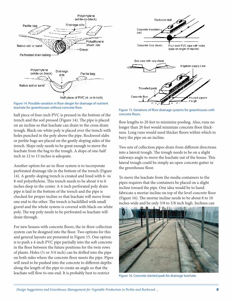
half piece of four-inch PVC is pressed in the bottom of the trench and the soil pressed (Figure 14). The pipe is placed on an incline so that leachate can drain to the cross drain trough. Black-on-white poly is placed over the trench with holes punched in the poly above the pipe. Rockwool slabs or perlite bags are placed on the gently sloping sides of the trench. Slope only needs to be great enough to move the leachate from the bag to the trough. A slope of one-half inch in 12 to 15 inches is adequate.
Another option for an in-floor system is to incorporate perforated drainage tile in the bottom of the trench (Figure 14). A gently-sloping trench is created and lined with 6- to 8-mil polyethylene. This trench needs to be about 4 to 6 inches deep in the center. A 4-inch perforated poly drain pipe is laid in the bottom of the trench and the pipe is checked for proper incline so that leachate will move from one end to the other. The trench is backfilled with small gravel and the whole system is covered with black-on-white poly. The top poly needs to be perforated so leachate will drain through.
For new houses with concrete floors, the in-floor collection system can be designed into the floor. Two options for this and general layouts are presented in Figure 15. One option is to push a 4-inch PVC pipe partially into the soft concrete in the floor between the future positions for the twin rows of plants. Holes (½ or 3/4 inch) can be drilled into the pipe on both sides where the concrete floor meets the pipe. Pipes will need to be pushed into the concrete to different depths along the length of the pipe to create an angle so that the leachate will flow to one end. It is probably best to restrict
flow lengths to 20 feet to minimize pooling. Also, runs no longer than 20 feet would minimize concrete floor thick-ness. Long runs would need thicker floors within which to bury the pipe on an incline.
Two sets of collection pipes drain from different directions into a lateral trough. The trough needs to be on a slight sideways angle to move the leachate out of the house. This lateral trough could be simply an open concrete gutter in the greenhouse floor.
To move the leachate from the media containers to the pipes requires that the containers be placed on a slight incline toward the pipe. One idea would be to hand-fabricate a mortar incline on top of the level concrete floor (Figure 16). The mortar incline needs to be about 8 to 10 inches wide and be only 3/8 to 5/8 inch high. Inclines can
Figure 14. Possible variation in floor desgin for drainage of nutrient leachate for greenhouses without concrete floor.
Figure 15. Variations of floor drainage systems for greenhouses with concrete floors.
Figure 16. Concrete slanted pads for drainage leachate.

9Design Suggestions and Greenhouse Management for Vegetable Production in Perlite and Rockwool ...
be built using pieces of lumber and troweling in concrete to build the incline from the PVC pipe to the board. All concrete and mortar surfaces need to be finished smoothly and sealed to facilitate movement of the leachate in the trough.
A second in-floor system for houses with new concrete floors would be to press two 2×4 pieces of lumber into the concrete and then remove after the concrete has set (Figure 17, Figure 18). A small, thin board should be placed between the 2×4s to make it easier to pop the lumber out of the concrete. The depressions remaining will serve as the collection trough. The lumber needs to be pressed in at dif-ferent depths along the length to achieve the drainage angle. Some individuals might find it easier to precision-place the 4×4 impression lumber prior to pouring the concrete. Mortar inclines are needed as above on which to place the rockwool slabs or perlite bags.
A third in-floor system for new houses is the lintel trough system. Lintel blocks are lined out in the sand floor, perhaps setting them in the floor so that 3 to 4 inches of the block
are above the sand grade. The concrete floor is poured level with the top of the blocks. A half piece of PVC is placed on a slope (using wood chocks) in the lintel trough to serve as the leachate conduit.
In the systems above, one could install water supply lines under the concrete floor that supply water to an outlet placed at the high end of each trough. Clean water then can be run down the troughs for periodic flushing of algae and debris. Another idea to help keep the troughs clean is to drape a piece of white-on-black polyethylene over one set of slabs or bags and trough. Slabs or bags are then placed on top of the poly. Holes are punched in the poly just above the trough. Leachate flows from the media containers over the poly surface and funnels through the holes in the poly and into the trough below.
Systems other than the ones proposed above can be devised. The key is to design one that will effectively move the leachate from the house. The incline for the support for the rockwool slab or perlite bag should be no more than about one-half inch in 12 to 15 inches. Floor trough incline probably should be 2 or 3 inches in 20 feet to move leachate from the collection-trough to the cross-trough that takes the leachate to the collection tank.
General layout of the collection system is presented in Figure 19. The reservoir tank size should be at least 300 to 500 gallons and should be buried so the opening is lower than the return troughs. Existing NFT (pipe) houses can use the old nutrient sump tank as the leachate reservoir. The outdoor reservoir should be painted or covered so that light cannot enter the tank, thus preventing algal growth. A
Figure 17. Additional ideas for floor drainage systems for greenhouses with concrete floors.
Figure 18. Drainage troughs created by pouring concrete floor around wooden forms and then removing forms, leaving behind troughs. Wooden benches also shown in photo. Figure 19. General layout of leachate collection system.
10Design Suggestions and Greenhouse Management for Vegetable Production in Perlite and Rockwool ...
sump pump in the tank facilitates pumping out the leachate which can be used for fertilizing pastures, gardens, nurser-ies, or lawns. Leachate should probably not be reused in the rockwool or perlite media since the leachate might contain disease organisms. Research on reuse is continuing.
Trellis SystemTomatoes and cucumbers need to be pruned of side shoots (suckers) and trained on a trellis. The planting pattern in the house consists of twin rows of slabs or bags placed on the inclined leachate boards or mortar pads. The distance from the center of one bag to the center of the bag across the trough is about 15 to 20 inches. The distance between centers of one twin-row and the next set, i.e., from one drain trough to the center of the next, should be 60 inches. At the head of each twin-row, a 4-inch iron pipe is concreted into the ground and floor to serve as the main end anchor for the trellis. It is a good idea to attach (bolt or weld) a piece of angle iron or other suitable support between the end post and the floor as a counter support or “deadman” for each post.
Across the top of each post, a 2×4 board or metal bracket is bolted to which to anchor the trellis wires. Each trellis wire (4/32 in. or 5/32 in. airplane cable) is anchored to one endpost with an eye bolt and to the other endpost through a cable tightener. There is one cable for each row of plants. Each plant is trained to the trellis cables using polypropyl-ene twine.
Irrigation SystemIn a rockwool or perlite house, water enters the house directly from the well, is mixed with fertilizer stocks by proportioners or injectors and applied to each plant via drip or micro-irrigation emitters. A backflow prevention system (check valve, pressure relief, and low pressure drain) are required for systems in which fertilizer will be injected. The water from the well should be filtered (150 mesh) to prevent damage to the fertilizer proportioners. A union connection installed before all major components will allow them to be removed for maintenance. Proportioners usually operate on a pressure differential basis so that installation in parallel is probably preferred over series. Nutrient solution should be filtered (150 mesh) prior to application to the plants. A pressure regulator should be installed to ensure the desired pressure in the greenhouse irrigation system.
Rockwool or perlite media receive water from individual emitters placed at the base of each plant. Emitters can be upright stake drippers. Each plant is irrigated from a short
length of spaghetti tubing plugged into a ½-inch or ¾-inch black poly lateral line.
Fertilizer stocks are stored in two containers (30 to 40-gal-lon size) under each proportioner. Stock tanks of this size will provide for 7-14 days of nutrient application. Stock tanks should be fitted with a lid through which the propor-tioner suction hoses fit.
Fertilizer formulas and programs that have been successful in Florida rockwool houses are presented in Appendix 1. More detail on fertilizer management for rockwool- and perlite-grown vegetables is presented in “Nutrient Solu-tion Formulation for Hydroponic (NFT and Rockwool) Tomatoes in Florida” (http://edis.ifas.ufl.edu/CV216). These nutrient solution formulas work equally well for rockwool and perlite.
In designing the fertilizer stock tank area, water lines and valves can be positioned above each stock tank for easy filling of stock tanks when mixing new nutrient solution. When mixing new solutions, the controller should be turned off so that proportioners will not remove unmixed stock solution.
Irrigation ControlThe irrigation system on/off cycles can be controlled by a “starting tray” placed under one rockwool slab in the greenhouse. The same starter tray can be used for perlite bag culture. The starting tray should be placed somewhere in the center of the house. The tray (Agrodynamics, Inc.) is wired to a relay box which is wired to an irrigation control-ler that controls the length of each water cycle by opening or shutting the electric solenoid valve. The relay, controller, and solenoid can be placed in the entrance porch. Control-lers should have battery backup so that programs are not lost during power outages. Growers need to be sure that the plants chosen for the tray are representative of the plants in the house (and remain so through the season).
To set up the starter tray, a representative spot with representative plants is chosen. It is best to choose a spot at least 20 to 30 feet away from the endwalls. The starter tray is positioned and leveled in all directions. The poly sleeve is cut away from the bottom of the chosen slab, and the exposed rockwool is positioned on the capillary mat in the tray. For perlite bags, holes are punched in the bottom side of the bag on a ½-inch grid. Holes should be about to ¼ inch in diameter so perlite media will have good contact with the capillary mat in the starter tray. Emitters are repositioned at the base of the plants.
11Design Suggestions and Greenhouse Management for Vegetable Production in Perlite and Rockwool ...
The irrigation system might need to be operated for a period to provide nutrient solution to fill the small “V”-shaped reservoir at one end of the tray. The electrical probe(s) is positioned so that the tip contacts the solution in the reservoir. Electrical connections and grounds are completed through the relay box and controller following directions supplied with the controller.
The basic irrigation scheduling theory revolves around applying enough solution to each slab or bag to fulfill plant needs and to maintain an acceptable electrical conductivity (soluble salt) level in the media. For most situations, this means that each irrigation event should apply about 4 ounces of solution per plant. The soluble salt reading of the leachate should be in the range of plus or minus 0.5 to 1.0 units from the applied nutrient solution. More or less nutrient solution can be applied to the plants to achieve this goal. Leachate for testing is collected from the media by a syringe.
Emitters for rockwool and perlite vegetables should have an inner diameter of at least .04 inch to reduce the risk of clogging. The irrigation management scheme involves designing a system that applies nutrient solution in ample amounts and in uniform fashion. Depending on the chosen emitter flow rates at a chosen operating pressure, the greenhouse irrigation might need to be constructed in zones. Flow rates of proportioners, pressure regulators, and pump capacity need to be considered.
Once the properly designed delivery system is in place, the starter tray determines when an irrigation event is needed. The controller determines the duration, and this setting will depend on the emitter flow rate, the need for soluble salt control mentioned above; duration will change as the crop develops. It is important that growers monitor crop growth and adjust the irrigation period accordingly. A full-grown tomato plant will use 1½ to 2 quarts of water on a sunny day.
Probe placement depth in the reservoir helps fine-tune the time interval between irrigation events. Shallow placement will mean that the system will come on more frequently because the plants will draw the reservoir level down to the probe setting faster than if the probe was set more deeply. A shallow setting might be useful early in the season when roots are not completely established to make sure the young plants receive ample nutrient solution. A deep setting might be useful later in the season to prevent overwatering on full-grown plants. Immediately after planting and for 3 to 4 weeks afterwards, irrigation should be controlled by timer to ensure frequent irrigations until the root system is well
developed and the plants are large enough to draw down the solution level in the starter tray to activate the irrigation system frequently enough.
There is no single, general purpose program for setting up the starter tray and controller. Each grower will need to determine settings for each situation. Assistance is available from the UF/IFAS Extension staff.
The starter tray will need attention to ensure continued operation success. The probe tip will occasionally develop a salt deposit. This salt must be scraped off and any algae in the reservoir removed. Roots in the probe area should be trimmed back. Growers should periodically check to see that the system is properly operated. One idea to help is to place one or two gallon jugs throughout the house into which an extra emitter is placed. Growers can prevent back siphoning of solution from the supply line to the jug by making sure the emitter tube to the jug is placed in the jug so the end of the tube is above the level of the irrigation supply line. These jugs can help determine if the system is operating and if the applications are uniform in the house. Growers also should get in the habit of making a periodic emitter flow rate check.
Winter HeatingGreenhouse vegetable production in Florida requires heating in the winter to ensure optimum production and freedom from freezing. Heating fuel can be from any source as determined by the grower. Most houses in northern Florida use LP furnaces. Other sources, if available, might be more economical than LP. Hot water requires the investment in the pipe distribution system. In designing the heating system for LP or gas heater, it is probably a good idea to place 2 heaters in the house. In the case of one heater failing, there will be a backup.
Heat is most economically delivered by distributing it on the floor of the greenhouse. For the LP furnaces, this means blowing the heated air into a plenum chamber attached to the front of the distribution fan. Make sure the fan is designed to handle the static pressure in the distribution system. Distribution ducts, both metal and polyethylene, take the heat to the floor ducts which run the length of the house under the plants. The floor ducts should be 8- or 10-inch poly distribution tubing with holes punched to evenly distribute heat down the length of the house. The tubing is placed on or near the floor between the rows of plants in each twin-row set but above the drainage troughs. Holes in the tubing should be positioned to distribute heat
12Design Suggestions and Greenhouse Management for Vegetable Production in Perlite and Rockwool ...
out both sides of the tubing upward at about a 45° angle into the plant canopy.
Placing the heat on the floor helps keep the roots warm and places the heat where its use can be maximized (in the plant canopy). If the distribution duct is placed in the ceiling of the house, then the attic must be heated before the plant area can benefit since hot air rises. In this system, air distribution fans would be needed to move the hot air downward. Floor tubes can be used for ventilation even if heat is not required.
In the floor heat distribution system, a heat retention cloth can be deployed on a cable system just above the plants to help retain the heat in the plant zone. If a polypropylene shade cloth is used as a heat retention cloth, it should be a thicker cloth (1.5 to 2.0 oz per yd).
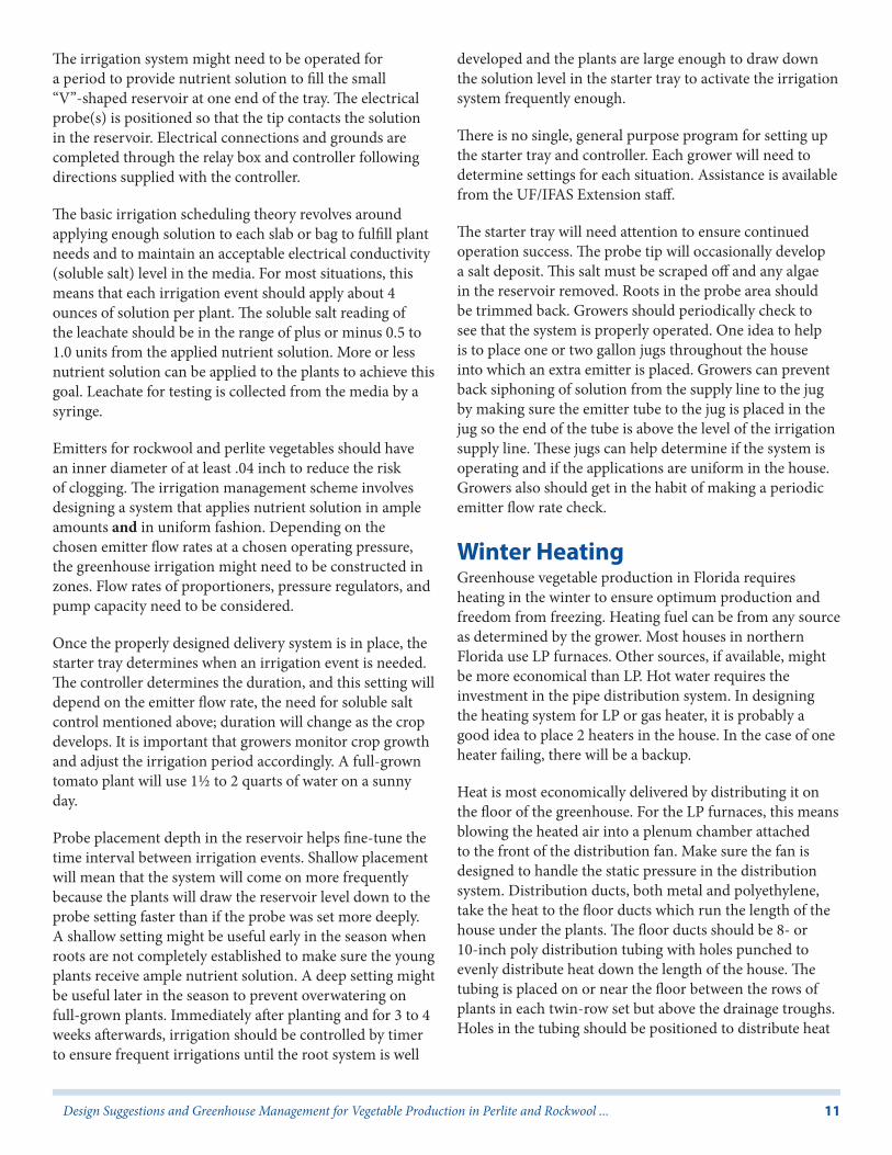
Horizontal air flow fans also are a good addition to a greenhouse heating and ventilation system (Figure 20). These small fans are placed above the plant canopy to move air around the greenhouse to assist in heating and also in drying the plants. For a typical single house, four fans are probably needed, two to push air down one side of the house and two to move air back. The net result is a circular movement of air about the greenhouse. Air flow fans are especially effective during winter when condensation is high and ventilation by exhaust fans is not needed. With the paucity of pesticides for disease control, ventilation and air movement to manage the greenhouse environment are required to minimize disease outbreak.
Shading SystemsVegetable culture in Florida during fall and spring requires shading to reduce heat buildup in the greenhouse. One system is to cover the house from the outside with a shade cover (Figure 4). A more flexible option is a double shading
system (roof and plant height level). To maximize flexibility, both systems should probably consist of shade cloths although shade compound paint could be used for roof shading.
The following information on shading is presented as a guideline since little research has been conducted in Florida to determine the best shading system and timing for green-house vegetables. Shade cloth thicknesses and management might need to be modified based on experience.
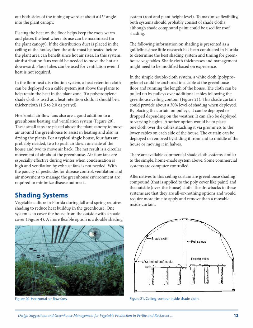
In the simple double-cloth system, a white cloth (polypro-pylene) could be anchored to a cable at the greenhouse floor and running the length of the house. The cloth can be pulled up by pulleys over additional cables following the greenhouse ceiling contour (Figure 21). This shade curtain could provide about a 30% level of shading when deployed. By placing the curtain on pulleys, it can be deployed or dropped depending on the weather. It can also be deployed to varying heights. Another option would be to place one cloth over the cables attaching it via grommets to the lower cables on each side of the house. The curtain can be deployed or removed by sliding it from end to middle of the house or moving it in halves.
There are available commercial shade cloth systems similar to the simple, home-made system above. Some commercial systems are computer controlled.
Alternatives to this ceiling curtain are greenhouse shading compound (that is applied to the poly cover like paint) and the outside (over-the-house) cloth. The drawbacks to these systems are that they are all-or-nothing options and would require more time to apply and remove than a movable inside curtain.
Figure 20. Horizontal air-flow fans. Figure 21. Ceiling-contour inside shade cloth.

13Design Suggestions and Greenhouse Management for Vegetable Production in Perlite and Rockwool ...
The second level of shading would consist of a plant-height cloth used over the plants at the 7- or 8-foot height (Figure 22). No detailed research has been conducted on a shade-cloth system for tomatoes in Florida. However, the following is offered as a suggestion for managing the two-cloth system. Modifications might be needed in some situations. These cloths (20 and 30% shade) are placed on 3/32-inch cables running the length of the house spaced about 5 feet apart. The 20% cloth would be used early in the season (March-April) and the 30% cloth would be used in May and June. The cloth is attached to the outside cables by grommets and rings so that the cloth can be moved back and forth. Moving the cloth is easier if it is cut across the middle and moved in halves, one half to the pad end of the house and one half to the fan end. The cable and grommet systems make it easy to deploy or remove the cover depend-ing on weather.
The plant-height shade cloth would provide a second level of shade when temperatures rise so high that the ceiling curtain cannot shade enough. With the plant-height curtain, optional attic fans could be brought into use to help remove the attic heat. In northern Florida, the time to begin shading would depend on temperatures inside the house. It is best to manage shading so that day temperatures are no higher than 88°F to 90°F for tomatoes. Maintaining temperatures in this range, or slightly below if possible, will minimize fruit ripening disorders such as solar yellowing. In Florida, this means that shading will probably need to be started by early March in most years. A suggested scheme for managing the ceiling/plant-height cloth system is presented in Table 1.
In the fall, both cloths might be needed for August, September, and part of October. Shading can gradually be
reduced through October and completely removed by mid November.
Rockwool and Perlite CultureAlthough rockwool slabs and perlite bags can be reused, there is significant risk involved in multiple cropping of these media. Media to be reused should be inspected for damage or compression and any damaged or crushed slabs or bags should be discarded. Old media should be sterilized by approved methods such as steaming. Simple disinfesta-tion will probably not be sufficient. For sterilization, the rockwool slabs are partially dried by letting the plants withdraw water at the end of the season. Slab covers are removed, slabs are stacked and sterilized. New sleeves are then placed over the slabs. Perlite media would need to be emptied from the bags and bulk-sterilized, then re-bagged.
Successful media reuse requires significant time investment and care to produce small financial savings. For many growers, the risk is not worth the savings. Some attempts to reuse rockwool slabs have not been successful. One potential problem has to do with irrigation management and Pythium root rot potential. If slabs are not well steril-ized, Pythium root rot can be a problem in the second crop. Reused slabs also contain considerable organic matter (old roots). The organic matter might cause the reused slabs to stay wetter early in the season for the second crop. If roots for the second crop become water logged, root rot can become serious.
When media is discarded, it should be disposed of properly. Rockwool could be ground up and used in potting mixes. Before doing this, the rockwool should be tested to be sure it is free of pathogens that might cause problems for the crop to be grown in the mix.
Another disposal mechanism might be to remove the cover, spread the slabs on a crop field, and till the slabs into the soil. Rototilling breaks the slabs into small pieces and the fragments are unnoticeable in a year. Perlite can be emptied onto the soil in a field and tilled in or can be used in soil mixes for landscaping.
After the greenhouse crop is finished, the irrigation supply lines should be cleaned and readied for next season. In most situations, fertilizer deposits and lime scale can be removed by acid cleaning of lines and emitters. Emitters should be removed from the media prior to acidification (if media is to be reused) so that acid will not destroy the media. A 1% solution of acid, phosphoric or sulfuric,
Figure 22. Inside shade cloth on a cable system.
14Design Suggestions and Greenhouse Management for Vegetable Production in Perlite and Rockwool ...
should be sufficient to cleanse emitters. After acidification, lines should be flushed.
Additional LiteratureSmith, D. L. 1987. Rockwool in horticulture. Grower Books, 50 Doughty St., London, WCIN 2LP. 153 pages.
Hochmuth, G. J. (ed.). 2002. Florida Greenhouse Vegetable Production Handbook, Volumes 1. http://edis.ifas.ufl.edu/topic_book_florida_greenhouse_v1 [September 2011].
Introduction, HS 766
Financial Considerations, HS767
Pre-Construction Considerations, HS768
Crop Production, HS769
Considerations for Managing Greenhouse Pests, HS770
Harvest and Handling Considerations, HS771
Marketing Considerations, HS772
Summary, HS773
Hochmuth, G. J. (ed.). 2002. Florida Greenhouse Vegetable Production Handbook, Volumes 2. http://edis.ifas.ufl.edu/topic_book_florida_greenhouse_v2
General Considerations, HS774
Site Selection, HS775
Physical Greenhouse Design Considerations, HS776
Production Systems, HS777
Greenhouse Environmental Design Considerations, HS778
Environmental Controls, HS779
Materials Handling, HS780
Other Design Information Resources, HS781
Hochmuth, G. J. (ed.). 2002. Florida Greenhouse Vegetable Production Handbook, Volumes 3. http://edis.ifas.ufl.edu/topic_book_florida_greenhouse_v3 [October 2011].
Preface, HS783
General Aspects of Plant Growth, HS784
Production Systems, HS785
Irrigation of Greenhouse Vegetables, HS786
Fertilizer Management for Greenhouse Vegetables, HS787
Production of Greenhouse Tomatoes, HS788
Generalized Sequence of Operations for Tomato Culture, HS789
Greenhouse Cucumber Production, HS790
Alternative Greenhouse Crops, HS791
Operational Considerations for Harvest, HS792
Enterprise Budget and Cash Flow for Greenhouse Tomato Production, HS793
Vegetable Disease Recognition and Control, HS797
Vegetable Insect Identification and Control, HS798
Hochmuth, B., and E. Belibasis. 1991. Costs of production for NFT greenhouse tomatoes in north Florida. Fla. Coop. Ext. Rpt. SVAREC 91-20.
Johnson, H. J., Jr., G. J. Hochmuth, and D. N. Maynard. 1985. Soilless culture of greenhouse vegetables. Fla. Coop. Ext. Sev. Circ. 218. 22 pages.
Laymon, C. A., and J. D. Farley. 1986. Proceedings of the 1986 annual American greenhouse vegetable growers association conference. P.O. Box 20228, Columbus, OH 43220.
Jones, J. B., Jr. 1983. A guide for the hydroponic and soilless culture grower. Timber Press, Portland, Oregon. 124 pages.
Savage, A. J. (Ed.) 1985. Hydroponics worldwide: State of the art in soilless crop production. International Center for Special Studies, 400 Hobron Lane, Suite 3502, Honolulu, HI 96815-1209.
Bucklin, R. 1987. Florida Greenhouse Design. UF/IFAS Extension Bull. 235.

15Design Suggestions and Greenhouse Management for Vegetable Production in Perlite and Rockwool ...
Appendix 1—Fertilizer Formulas and Programs for Florida Rockwool and Perlite HousesTables 2 and Table 3 give general reference information for handling dry fertilizer materials. Table 2 is a list of approxi-mate weight equivalents for dry measures of eight fertilizer ingredients. Table 3 gives handy equivalents between the weight of a nutrient and the parts per million provided when it is diluted 1 to 100 in a 30-gallon tank.
Tomato Nutrient Solution Formulations
Following are four fertilizer recipes that have been success-ful in Florida rockwool houses. More detail on fertilizer management for rockwool- and perlite-grown vegetables is presented in “Nutrient Solution Formulation for Hydro-ponic (NFT and Rockwool) Tomatoes in Florida” (http://edis.ifas.ufl.edu/CV216). These nutrient solution formulas work equally well for rockwool and perlite.
• Recipe 1 (Table 4, Table 5); Stock Solutions and Final Concentrations
• Recipe 2 (Table 6, Table 7); Stock Solutions and Final Concentrations
• Recipe 3 (Table 8, Table 9); Stock Solutions and Final Concentrations
• Recipe 4 (Table 10, Table 11); Stock Solutions and Final Concentrations
Appendix 2—Estimated Construction and Operating Costs for Rockwool or Perlite TomatoesTable 12 and Table 13 present estimated costs to construct and operate a greenhouse for rockwool or perlite tomatoes. The house is a 120 by 35 foot house containing 1100 tomato plants. Labor costs are assumed as $5.25 per hour. Some of the cost estimates below were adapted from SVAREC 91-20 report by Hochmuth and Belibasis which deals with NFT. The major differences for costs between NFT and rockwool solid media systems are:
1. No need for concrete floor with solid media systems.
2. Less construction labor for rockwool or perlite house due to lack of need for concrete floor.
3. Less operating labor for solid media due to automated irrigation system.
4. Slightly more cost for irrigation system with solid media.
5. Need to replace solid media.
In the final analysis, the total costs for NFT and solid media houses are very similar. The major difference is consistently high yields from rockwool or perlite compared to NFT with PVC pipe. This makes profitability with rockwool or perlite more consistent.

16Design Suggestions and Greenhouse Management for Vegetable Production in Perlite and Rockwool ...
Appendix 3—Partial Checklist of Equipment and Supplies for a Perlite or Rockwool HouseI. Pump and well
II. Greenhouse structure
A. Galvanized pipe
1. Side wall columns
2. Arches
3. Endwall frames
4. Purlins
5. Heater hangers
6. Braces
B. Aluminum extrusion
1. Arch poly locking
2. Base board poly locking
3. Eave poly locking
4. Cooling pad cover poly locking
5. Endwall cross members
III. Environmental control
A. Heating
1. Two furnaces
2. Jet fan and plenum
3. Heat distribution tubing
4. Inlet shutter for jet fan
5. Heat retention cloth
6. Thermostats or control system
7. Furnace ventilator stacks
8. Fuel tank and hook-up
9. Temperature alarm
10. Thermometers
11. Electric generator (backup electricity)
B. Ventilation
1. Exhaust fans (slant-wall) with shutters
2. Attic exhaust fans
3. Cooling pad and delivery and return system
4. Cooling pad sump tank, pump, and float control
5. Motorized shutter vents
6. Thermostats or controller
7. Insect screen or cloth
C. Shading System
1. Airplane cables, eyebolts, and tighteners
2. Shade cloth (20 and 30%)
3. Pulleys, grommets, etc.
IV. Greenhouse coverings
1. Polyethylene cover (roof, side walls) (double-layer) and inflating blower.
2. Endwalls - fiberglass, polycarbonate, etc.
3. Poly patching rolls
4. Foam sealant
V. Entrance porch
1. Concrete floor
2. Covering - fiberglass
3. Wall framing-pipe, aluminum, or wood
4. Doors
VI. Contract services
1. Electrical (lights, wiring), at least 100 AMPS
17Design Suggestions and Greenhouse Management for Vegetable Production in Perlite and Rockwool ...
2. Plumbing - well
VII. Greenhouse floor
1. Sand, concrete, site prep.
2. Framing for concrete
3. Leachate trough system
4. Plumbing
5. Nursery cloth
6. Black-on-white poly
VIII. Irrigation
1. Proportioners
2. Water supply-check valve, filters, pressure regulator
3. Black poly distribution tubing (1/2 and 3/4 inch)
4. Emitters
5. Irrigation starter tray
6. Relay box and wire
7. Controller and solenoid
IX. Production supplies
1. Rockwool slabs or perlite lay-flat bags (2 to 3 plants per container)
2. Transplant seeding cubes and blocks, and trays
3. Seeds
4. Trellis lumber, posts, cable, and tighteners
5. Trellis twine
6. Soluble salt meter and standard solution
7. Pollinator
8. Plant clips, tapener machine, and tape
9. Light meter
10. Fertilizer stock tanks
11. Mist blower sprayer
12. Fertilizer, chemicals, and acid
13. Spray suit and safety equipment
14. Harvesting buckets
15. Scales-measure fertilizer
16. Record book
17. Insect monitoring yellow sticky cards
18. Pruning shears
19. Heating fuel
20. Vacuum cleaner
21. Copy of the “Handbook for Greenhouse Vegetable Production in Florida”

18Design Suggestions and Greenhouse Management for Vegetable Production in Perlite and Rockwool ...
Table 1. Suggested spring shade management scheme for the two-cloth shading system for Florida.Approximate time period z Operation
March 1-15 Deploy 20% plant-height cloth
March 16-31 Pull back plant-height cloth and deploy 30% ceiling cloth alone
April 1-June 30 Deploy both clothsz Exact deployment periods will depend on specific prevailing weather conditions.
Table 2. Approximate weight (grams) for several measuring utensils.Fertilizer 1 Teaspoon
(level)1 Tablespoon
(level)one dry “ounce” in meas. cupz
Sequestrene Fe 330 4 12 20
Ammonium molybdate 7 -- --
Sodium molybdate 4 -- --
Solubor 2 6 10
S.T.E.M. 5 15 25
Manganese sulfate 6 18 30
Zinc sulfate 5 15 26
Copper sulfate 7 21 35z “Ounce” refers to the “ounce” line on a measuring cup. Differences in weights of an “ounce” of material are due to differences in densities of materials.

19Design Suggestions and Greenhouse Management for Vegetable Production in Perlite and Rockwool ...
Table 3. The ppm of a specific nutrient provided by a specified amount of a particular fertilizer material for a 30-gallon stock tank and a final dilution of 1:100.
Amount of Material Material Chemical Analysis ppm Nutrient Provided
1 lb Potassium nitrate 13% N, 36.5% K 5 ppm N
14.5 ppm K
1 lb Ammonium nitrate 33.5% N 13.3 ppm N
1 lb Potassium chloride 51% K 20.3 ppm K
1 lb Magnesium sulfate 10% Mg, 14% S 4 ppm Mg
5.6 ppm S
1 pint Liquid Ca(NO3)2 7% N, 11% Ca 4.2 ppm N
6.6 ppm Ca
1 lb Dry Ca(NO3)2 15.5% N, 19% Ca 6.1 ppm N
7.5 ppm Ca
1 lb Calcium chloride 36% Ca 14.3 ppm Ca
1 quart Phosphoric acid 23% P 30 ppm P
1 gramz Solubor 20.5% B 0.018 ppm B
0.5 lb Fe 330 chelated iron 10% Fe 2.0 ppm Fe
100 grams S.T.E.M. (Soluble Trace Element Mix) 1.35% B 0.12 ppm B
3.2% Cu 0.28 ppm Cu
7.5% Fe 0.66 ppm Fe
8% Mn 0.70 ppm Mn
0.04% Mo 0.0035 ppm Mo
4.5 % Zn 0.39 ppm Zn
1 gram CuSO4 (copper sulfate)
25% Cu 0.021 ppm Cu
1 gram MnSO4 (manganese sulfate)
28% Mn 0.024 ppm Mn
1 gram ZnSO4 (zinc sulfate)
36% Zn 0.03 ppm Zn
1 mlz Liquid sodium molybdate 17% Mo 0.02 ppm Mo
1 gram Dry sodium molybdate 40% Mo 0.03 ppm Mo
1 lb Monopotassium phosphate 23% P, 28% K 9 ppm P
11 ppm Kz Growers will need to use a gram scale or laboratory pipette to measure amounts of micronutrients or will need to calibrate a measuring spoon set to provide the correct amount of micronutrient materials.

20Design Suggestions and Greenhouse Management for Vegetable Production in Perlite and Rockwool ...
Table 4. Recipe 1 - Tomato Nutrient Solution Formulation; Stock SolutionsStage of Growth
1 2 3 4 5
Transplant to first cluster
First cluster to second cluster
Second cluster to third cluster
Third cluster to fifth cluster
Fifth cluster to termination
A STOCK 3.3 pts Phos. acid
3.3 pts Phos. acid
3.3 pts Phos. acid
3.3 pts Phos. acid
3.3 pts Phos. acid
6 lb KCl 6 lb KCl 6 lb KCl 6 lb KCl 6 lb KCl
10 lb MgSO4 10 lb MgSO4 10 lb MgSO4 12 lb MgSO4 12 lb MgSO4
2 lb KNO3 2 lb KNO3 6 lb KNO3
1 lb NH4NO3
10 gr CuSO4 10 gr CuSO4 10 gr CuSO4 10 gr CuSO4 10 gr CuSO4
35 gr MnSO4 35 gr MnSO4 35 gr MnSO4 35 gr MnSO4 35 gr MnSO4
10 gr ZnSO4 10 gr ZnSO4 10 gr ZnSO4 10 gr ZnSO4 10 gr ZnSO4
40 gr Solubor 40 gr Solubor 40 gr Solubor 40 gr Solubor 40 gr Solubor
3 ml Na moly 3 ml Na moly 3 ml Na moly 3 ml Na moly 3 ml Na moly
B STOCK 2.1 gal Ca(NO3)2
or 11.5 lb dry Ca(NO3)2
2.4 gal Ca(NO3)2
or 13.1 lb dry Ca(NO3)2
2.7 gal Ca(NO3)2
or 14.8 lb dry Ca(NO3)2
3.3 gal Ca(NO3)2
or 18.0 lb dry Ca(NO3)2
3.3 gal Ca(NO3)2
or 18.0 lb dry Ca(NO3)2
0.7 lb Fe 330 0.7 lb Fe 330 0.7 lb Fe 330 0.7 lb Fe 330 0.7 lb Fe 330
NOTE: Calculations in above table are for amount of fertilizer material in 30-gal stock tanks and then for a 1:100 dilution (1 gal each stock in 100 gals final nutrient solution). Fertilizer amounts placed in each stock tank will need to be doubled if proportioner (1:100) pumps are installed in parallel in same water incoming line.
Table 5. Recipe 1 - Tomato Nutrient Solution Formulations; Final ConcentrationsStage of Growth
1 2 3 4 5
Transplant to first cluster
First cluster to second cluster
Second cluster to third cluster
Third cluster to fifth cluster
Fifth cluster to termination
N 70 80 100 120 153
P 50 50 50 50 50
K 119 119 148 148 206
Ca 111 (86)z 127 (98) 143 (111) 174 (135) 174 (135)
Mg 40 40 40 48 48
S 56 56 56 66 66
Fe 2.8 2.8 2.8 2.8 2.8
Cu 0.2 0.2 0.2 0.2 0.2
Mn 0.8 0.8 0.8 0.8 0.8
Zn 0.3 0.3 0.3 0.3 0.3
B 0.7 0.7 0.7 0.7 0.7
Mo 0.06 0.06 0.06 0.06 0.06z Numbers in parentheses are the ppm Ca when dry Ca(NO3)2 is used instead of liquid.
Calcium, magnesium, and sulfur values will vary upwards depending on the amount of calcium and magnesium coming from the water source, and the amount of sulfur coming from the sulfuric acid used for acidification.

21Design Suggestions and Greenhouse Management for Vegetable Production in Perlite and Rockwool ...
Table 6. Recipe 2 - Tomato Nutrient Solution Formulation; Stock SolutionsStage of Growth
1 2 3 4 5
Transplant to first cluster
First cluster to second cluster
Second cluster to third cluster
Third cluster to fifth cluster
Fifth cluster to termination
A STOCK 3.3 pts Phos. acid
3.3 pts Phos. acid
3.3 pts Phos. acid
3.3 pts Phos. acid
3.3 pts Phos. acid
6 lb KCl 6 lb KCl 6 lb KCl 6 lb KCl 6 lb KCl
10 lb MgSO4 10 lb MgSO4 10 lb MgSO4 12 lb MgSO4 12 lb MgSO4
2 lb KNO3 2 lb KNO3 6 lb KNO3
1 lb NH4NO3
100 gr S.T.E.M. 100 gr S.T.E.M. 100 gr S.T.E.M. 100 gr S.T.E.M. 100 gr S.T.E.M.
40 gr Solubor 40 gr Solubor 40 gr Solubor 40 gr Solubor 40 gr Solubor
3 ml Na moly 3 ml Na moly 3 ml Na moly 3 ml Na moly 3 ml Na moly
B STOCK 2.1 gal Ca(NO3)2
or 11.5 lb dry Ca(NO3)2
2.4 gal Ca(NO3)2
or 13.1 lb dry Ca(NO3)2
2.7 gal Ca(NO3)2
or 14.8 lb dry Ca(NO3)2
3.3 gal Ca(NO3)2
or 18.0 lb dry Ca(NO3)2
3.3 gal Ca(NO3)2
or 18.0 lb dry Ca(NO3)2
0.5 lb Fe 330 0.5 lb Fe 330 0.5 lb Fe 330 0.5 lb Fe 330 0.5 lb Fe 330
NOTE: Calculations in above table are for amount of fertilizer material in 30-gal stock tanks and then for a 1:100 dilution (1 gal each stock in 100 gals final nutrient solution). Fertilizer amounts placed in each stock tank will need to be doubled if proportioner (1:100) pumps are installed in parallel in same water incoming line.
Table 7. Recipe 2 - Tomato Nutrient Solution Formulation; Final ConcentrationsStage of Growth
1 2 3 4 5
Transplant to first cluster
First cluster to second cluster
Second cluster to third cluster
Third cluster to fifth cluster
Fifth cluster to termination
N 70 80 100 120 150
P 50 50 50 50 50
K 119 119 148 148 206
Ca 111 (86)z 127 (98) 143 (111) 174 (135) 174 (135)
Mg 40 40 40 48 48
S 56 56 56 66 66
Fe 2.7 2.7 2.7 2.7 2.7
Cu 0.28 0.28 0.28 0.28 0.28
Mn 0.7 0.7 0.7 0.7 0.7
Zn 0.39 0.39 0.39 0.39 0.39
B 0.84 0.84 0.84 0.84 0.84
Mo 0.06 0.06 0.06 0.06 0.06z Numbers in parentheses are the ppm Ca when dry Ca(NO3)2 is used instead of liquid.
Calcium, magnesium, and sulfur values will vary upwards depending on the amount of calcium and magnesium coming from the water source, and the amount of sulfur coming from the sulfuric acid used for acidification.

22Design Suggestions and Greenhouse Management for Vegetable Production in Perlite and Rockwool ...
Table 8. Recipe 3 - Tomato Nutrient Solution Formulations; Stock SolutionsStage of Growth
1 2 3 4 5
Transplant to first cluster
First cluster to second cluster
Second cluster to third cluster
Third cluster to fifth cluster
Fifth cluster to termination
A STOCK 5.5 lb KH2PO4 5.5 lb KH2PO4 5.5 lb KH2PO4 5.5 lb KH2PO4 5.5 lb KH2PO4
4 lb KNO3 4 lb KNO3 5 lb KNO3 8 lb KNO3 8 lb KNO3
10 lb MgSO4 10 lb MgSO4 10 lb MgSO4 12 lb MgSO4 12 lb MgSO4
1 lb KCl 1 lb KCl 1 lb KCl
2 lb NH4NO3
10 gr Cu SO4 10 gr Cu SO4 10 gr Cu SO4 10 gr Cu SO4 10 gr Cu SO4
35 gr Mn SO4 35 gr Mn SO4 35 gr Mn SO4 35 gr Mn SO4 35 gr Mn SO4
10 gr Zn SO4 10 gr Zn SO4 10 gr Zn SO4 10 gr Zn SO4 10 gr Zn SO4
40 gr Solubor 40 gr Solubor 40 gr Solubor 40 gr Solubor 40 gr Solubor
3 ml Na moly 3 ml Na moly 3 ml Na moly 3 ml Na moly 3 ml Na moly
B STOCK 1.5 gal Ca(NO3)2
or 8.2 lb dry Ca(NO3)2
1.8 gal Ca(NO3)2
or 9.8 lb dry Ca(NO3)2
2.2 gal Ca(NO3)2
or 12.3 lb dry Ca(NO3)2
2.4 gal Ca(NO3)2
or 13.1 lb dry Ca(NO3)2
2.5 gal Ca(NO3)2
or 13.7 lb dry Ca(NO3)2
0.7 lb Fe 330 0.7 lb Fe 330 0.7 lb Fe 330 0.7 lb Fe 330 0.7 lb Fe 330
NOTE: Calculations in the table above are for amount of fertilizer material in 30-gal stock tanks and then for a 1:100 dilution (1 gal each stock in 100 gals final nutrient solution). Fertilizer amounts placed in each stock tank will need to be doubled if proportioner (1:100) pumps are installed in parallel in same water incoming line.
Table 9. Recipe 3 - Tomato Nutrient Solution Formulations; Final ConcentrationsStage of Growth
1 2 3 4 5
Transplant to first cluster
First cluster to second cluster
Second cluster to third cluster
Third cluster to fifth cluster
Fifth cluster to termination
N 70 80 100 120 150
P 50 50 50 50 50
K 119 119 153 153 196
Ca 79 (61)z 94 (74) 118 (92) 126 (98) 131 (103)
Mg 40 40 40 48 48
S 56 56 56 66 66
Fe 2.8 2.8 2.8 2.8 2.8
Cu 0.2 0.2 0.2 0.2 0.2
Mn 0.8 0.8 0.8 0.8 0.8
Zn 0.3 0.3 0.3 0.3 0.3
B 0.7 0.7 0.7 0.7 0.7
Mo 0.06 0.06 0.06 0.06 0.06z Numbers in parentheses are the ppm Ca when dry Ca(NO3)2 is used instead of liquid.
Calcium, magnesium, and sulfur values will vary upwards depending on the amount of calcium and magnesium coming from the water source, and the amount of sulfur coming from the sulfuric acid used for acidification.

23Design Suggestions and Greenhouse Management for Vegetable Production in Perlite and Rockwool ...
Table 10. Recipe 4 - Tomato Nutrient Solution Formulations; Stock SolutionsStage of Growth
1 2 3 4 5
Transplant to first cluster
First cluster to second cluster
Second cluster to third cluster
Third cluster to fifth cluster
Fifth cluster to termination
A STOCK 3.3 pts Phos. acid
3.3 pts Phos. acid
3.3 pts Phos. acid
3.3 pts Phos. acid
3.3 pts Phos. acid
8.3 lb KNO3 8.3 lb KNO3 10.3 lb KNO3 10.3 lb KNO3 13.8 lb KNO3
10 lb MgSO4 10 lb MgSO4 10 lb MgSO4 12 lb MgSO4 12 lb MgSO4
100 gr S.T.E.M. 100 gr S.T.E.M. 100 gr S.T.E.M. 100 gr S.T.E.M. 100 gr S.T.E.M.
40 gr Solubor 40 gr Solubor 40 gr Solubor 40 gr Solubor 40 gr Solubor
3 ml Na moly 3 ml Na moly 3 ml Na moly 3 ml Na moly 3 ml Na moly
B STOCK 6.7 pts Ca(NO3)2
or 4.6 lb dry Ca(NO3)2
9 pts Ca(NO3)2
or 6.2 lb dry Ca(NO3)2
11.4 pts Ca(NO3)2
or 7.9 lb dry Ca(NO3)2
2 gal Ca(NO3)2
or 11.1 lb dry Ca(NO3)2
2.4 gal Ca(NO3)2
or 13.3 lb dry Ca(NO3)2
0.7 lb Fe 330 0.7 lb Fe 330 0.7 lb Fe 330 0.7 lb Fe 330 0.7 lb Fe 330
NOTE: Calculations in these tables are for amount of fertilizer material in 30-gal stock tanks and then for a 1:100 dilution (1 gal each stock in 100 gals final nutrient solution). Fertilizer amounts placed in each stock tank will need to be doubled if proportioner (1:100) pumps are installed in parallel in same water incoming line.
Table 11. Recipe 4 - Tomato Nutrient Solution Formulation; Final ConcentrationsStage of Growth
1 2 3 4 5
Transplant to first cluster
First cluster to second cluster
Second cluster to third cluster
Third cluster to fifth cluster
Fifth cluster to termination
N 70 80 100 120 150
P 50 50 50 50 50
K 120 120 150 150 200
Ca 44 (35)z 59 (47) 75 (59) 105 (83) 127 (100)
Mg 40 40 40 48 48
S 56 56 56 67 67
Fe 2.7 2.7 2.7 2.7 2.7
Cu 0.28 0.28 0.28 0.28 0.28
MN 0.7 0.7 0.7 0.7 0.7
Zn 0.39 0.39 0.39 0.39 0.39
B 0.84 0.84 0.84 0.84 0.84
Mo 0.06 0.06 0.06 0.06 0.06z Numbers in parentheses are the ppm Ca when dry Ca(NO3)2 is used instead of liquid.
Calcium, magnesium, and sulfur values will vary upwards depending on the amount of calcium and magnesium coming from the water source, and the amount of sulfur coming from the sulfuric acid used for acidification.
Table 12. Investment costs for rockwool or perlite tomatoes in Florida.Original Cost Expected Life
(Yrs)Depreciation
Greenhouse: including site preparation, systems, and labor.
$24,760y 10 $2,530
Durables: including poly cover, cooling pads, sprayer, media benches, leachate collection, and production tools.
$3,905 3 to 5 $961
Total investment $28,665 $3,491y Does not include well and pump.

24Design Suggestions and Greenhouse Management for Vegetable Production in Perlite and Rockwool ...
Table 13. Budget summary for rockwool or perlite tomatoes in Florida.Production System Rockwool Crop Duration - weeks 42
No. of Greenhouses 1 Harvest Period - weeks 30
Dimensions 35’ x 120’ Miles to packinghouse 15
No. of Plants/GH 1100 Trips to packinghouse 83
Labor Rate $/hr 5.25
Revenue Price $/lb Total $
Total 27500 0.9 24750
Per plant 25
Costs Unit Quantity Price Value Totals
Preharvest
Rockwool slabs each 370 2.25 833
Rockwool blocks 1100 0.3 330
Fertilizer/Fertigation $ 1 691 691
Pesticides $ 1 58 58
Other Mat. Inputs $ 1 675 675
LP Gas $ 1 1624 1624
Labor hrs 660 5.25 3465
Electricity kwh $ 1 1179 1179
Repairs $ 1 143 143
Int. on Op. Capital* $ 8998 0.03 270
Total Preharvest Cost 9267
Fixed Costs
Depreciation $ 1 3491 3491
In. on Investment Capital $ 1 1433 1433
Taxes & Ins. $ 1 205 205
Total Fixed 5129
Harvest & Hauling
Labor hrs 160 5.25 840
Vehicle** mi 5430 0.25 1358
Total Harvest/Hauling Costs 2198
Packing & Marketing
Labor, Boxes & Mkt. lbs 27500 0.25 6875
Total Packaging & Marketing 6875
Total Cost 23469
Returns Above Cash Costs 6410
Returns to Risk & Management 1281
Breakeven Price to Cover Cash Costs 0.67
Breakeven Price to Cover Total Costs 0.85


![6'OOOß 30 H 4Ê30B(Ê) TRIP COOL STAGE 2-WAY GRILL [RED] No ... · ——6'oooß 30 h 4Ê30b(Ê) trip cool stage 2-way grill [red] no. d tel-0736-62-2611 500b 20s 30b ffkfi*3e 1](https://img.dokumen.tips/doc/110x75/601d845a15b89041806f0180/6ooo-30-h-430b-trip-cool-stage-2-way-grill-red-no-aa6ooo-30.jpg)