Embed Size (px)
Citation preview
Assets Delivery Group Engineering
DESIGN STANDARD DS 79
Design of Chemical Systems
- Legislative Requirements and General Principles
VERSION 2
REVISION 0
OCTOBER 2017

Design Standard No. DS 79
Design of Chemical Systems – Legislative Requirements and General Principles
Uncontrolled if Printed Page 2 of 39
Ver2 Rev0
© Copyright Water Corporation 2012-2017
FOREWORD
The intent of Design Standards is to specify requirements that assure effective design and delivery of fit for
purpose Water Corporation infrastructure assets for best whole-of-life value with least risk to Corporation service
standards and safety. Design standards are also intended to promote uniformity of approach by asset designers,
drafters and constructors to the design, construction, commissioning and delivery of water infrastructure and to the
compatibility of new infrastructure with existing like infrastructure.
Design Standards draw on the asset design, management and field operational experience gained and documented
by the Corporation and by the water industry generally over time. They are intended for application by Corporation
staff, designers, constructors and land developers to the planning, design, construction and commissioning of
Corporation infrastructure including water services provided by land developers for takeover by the Corporation.
Nothing in this Design Standard diminishes the responsibility of designers and constructors for applying the
requirements of WA OSH Regulations 1996 (Division 12, Construction Industry – consultation on hazards and
safety management) to the delivery of Corporation assets. Information on these statutory requirements may be
viewed at the following web site location:
https://www.slp.wa.gov.au/legislation/agency.nsf/docep_law_s4665.html
Enquiries relating to the technical content of a Design Standard should be directed to the Senior Principal
Engineer, Water Treatment, Engineering. Future Design Standard changes, if any, will be issued to registered
Design Standard users as and when published.
Head of Engineering
This document is prepared without the assumption of a duty of care by the Water Corporation. The document is not intended
to be nor should it be relied on as a substitute for professional engineering design expertise or any other professional advice.
Users should use and reference the current version of this document.
© Copyright – Water Corporation: This standard and software is copyright. With the exception of use permitted by the
Copyright Act 1968, no part may be reproduced without the written permission of the Water Corporation.
Design Standard No. DS 79
Design of Chemical Systems – Legislative Requirements and General Principles
Uncontrolled if Printed Page 3 of 39
Ver2 Rev0
© Copyright Water Corporation 2012-2017
DISCLAIMER
Water Corporation accepts no liability for any loss or damage that arises from anything in the
Standards/Specifications including any loss or damage that may arise due to the errors and omissions of any
person. Any person or entity which relies upon the Standards/Specifications from the Water Corporation website
does so that their own risk and without any right of recourse to the Water Corporation, including, but not limited
to, using the Standards/Specification for works other than for or on behalf of the Water Corporation.
The Water Corporation shall not be responsible, nor liable, to any person or entity for any loss or damage suffered
as a consequence of the unlawful use of, or reference to, the Standards/Specifications, including but not limited to
the use of any part of the Standards/Specification without first obtaining prior express written permission from the
CEO of the Water Corporation.
Any interpretation of anything in the Standards/Specifications that deviates from specific Water Corporation
Project requirements must be referred to, and resolved by, reference to and for determination by the Water
Corporation’s project manager and/or designer for that particular Project.

Design Standard No. DS 79
Design of Chemical Systems – Legislative Requirements and General Principles
Uncontrolled if Printed Page 4 of 39
Ver2 Rev0
© Copyright Water Corporation 2012-2017
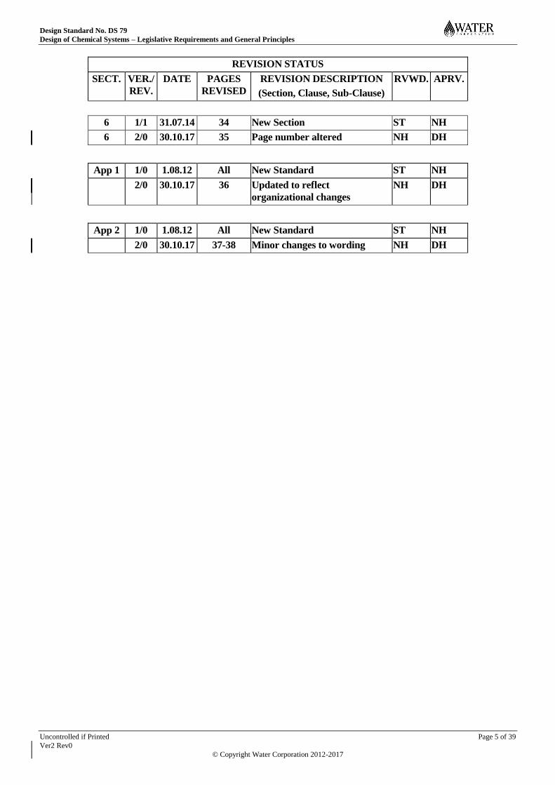
REVISION STATUS
The revision status of this standard is shown section by section below:
REVISION STATUS
SECT. VER./
REV.
DATE PAGES
REVISED
REVISION DESCRIPTION
(Section, Clause, Sub-Clause)
RVWD. APRV.
1 1/0 1.08.12 All New Standard ST NH
1 1/1 31.07.14 7 Section 1.2 revised ST NH
1 1/1 31.07.14 8-10 Section 1.3.4, 1.3.5 and Section
1.4 revised
ST NH
1 2/0 30.10.17 8 Section 1.2 revised NH DH
2 1/0 1.08.12 All New Standard ST NH
2 1/1 31.07.14 12 Section 2.2.1, 2.2.2 revised ST NH
2 2/0 30.10.17 12-13 Section 2 – minor wording
changes
NH DH
3 1/0 1.08.12 All New Standard ST NH
3 1/1 31.07.14 13-14 Section3, 3.1 revised ST NH
3 2/0 30.10.17 14-15 Sections 3.1 and 3.3 amended NH DH
4 1/0 1.08.12 All New Standard ST NH
4 1/1 31.07.14 15-19 Section 4, 4.1, 4.2.2, 4.2.3, 4.2.4,
4.3, 4.4, 4.5, 4.8
ST NH
4 2/0 30.10.17 16-18 Sections 4.2.1, 4.2.2 and 4.5
amended
NH DH
5 1/0 1.08.12 All New Standard ST NH
5 1/1 31.07.14 20-21 Sections 5.1.1, 5.1.2, 5.1.3
revised
ST NH
5 1/1 31.07.14 22-23 Section 5.2 revised ST NH
5 1/1 31.07.14 23-26 Sections 5.4.1, 5.4.2, 5.4.3
revised
ST NH
5 1/1 31.07.14 27-29 Sections 5.5.1, 5.5.2 revised ST NH
5 1/1 31.07.14 30-32 Sections 5.6.1, 5.6.2, 5.6.3, 5.6.4,
5.6.5 revised
ST NH
5 1/1 31.07.14 32 Section 5.7 revised ST NH
5 1/1 31.07.14 32-33 Sections 5.8, 5.8.1, 5.8.2, 5.8.2.1,
5.8.2.2, 5.8.3 revised
ST NH
5 2/0 30.10.17 23,25,35 Sections 5.1.2&5.4.2 valving
requirements changed, Section
5.5.1 amended to cover tank
material selection. Section 5.9
added
NH DH
Design Standard No. DS 79
Design of Chemical Systems – Legislative Requirements and General Principles
Uncontrolled if Printed Page 5 of 39
Ver2 Rev0
© Copyright Water Corporation 2012-2017
REVISION STATUS
SECT. VER./
REV.
DATE PAGES
REVISED
REVISION DESCRIPTION
(Section, Clause, Sub-Clause)
RVWD. APRV.
6 1/1 31.07.14 34 New Section ST NH
6 2/0 30.10.17 35 Page number altered NH DH
App 1 1/0 1.08.12 All New Standard ST NH
2/0 30.10.17 36 Updated to reflect
organizational changes
NH DH
App 2 1/0 1.08.12 All New Standard ST NH
2/0 30.10.17 37-38 Minor changes to wording NH DH

Design Standard No. DS 79
Design of Chemical Systems – Legislative Requirements and General Principles
Uncontrolled if Printed Page 6 of 39
Ver2 Rev0
© Copyright Water Corporation 2012-2017
DESIGN STANDARD DS 79 Design of Chemical Systems – Legislative Requirements and
General Principles
CONTENTS Section Page
1 INTRODUCTION ......................................................................................................................... 8
1.1 Purpose ......................................................................................................................................... 8
1.2 Background Information ............................................................................................................ 8
1.3 Regulations and Standards ......................................................................................................... 8 1.3.1 Department of Mines, Industry Regulation and Safety – Dangerous Goods Division .................. 8 1.3.2 Worksafe Western Australia .......................................................................................................... 8 1.3.3 Health Department of Western Australia ...................................................................................... 8 1.3.4 Water Corporation Standards ........................................................................................................ 9 1.3.5 Australian Standards .................................................................................................................... 10
1.4 Abbreviations and Terminology ............................................................................................... 10
2 LEGISLATIVE REQUIREMENTS ......................................................................................... 12
2.1 Licensing - Overview ................................................................................................................. 12
2.2 Dangerous Goods Licensing - Requirements .......................................................................... 12 2.2.1 Major Hazard Facility Notifications ............................................................................................ 12 2.2.2 Dangerous Goods License Applications ...................................................................................... 13
2.3 Poisons Permits .......................................................................................................................... 13
3 WATER CORPORATION REQUIREMENTS ...................................................................... 14
3.1 Estimating Chlorine Buffers ..................................................................................................... 14
3.2 Ammonia Buffers ....................................................................................................................... 15
3.3 Buffer Risk Mitigation Options ................................................................................................ 15
4 DESIGN PRINCIPLES – RISK MANAGEMENT ................................................................. 16
4.1 Housing of Corrosive Chemical Facilities in Buildings .......................................................... 16
4.2 Design Features of Housed Chemical Facilities ...................................................................... 16 4.2.1 Ventilation ................................................................................................................................... 16 4.2.2 PPE and First Aid Storage ........................................................................................................... 17 4.2.3 Personnel Doors ........................................................................................................................... 17 4.2.4 Layout and Design ....................................................................................................................... 17
4.3 Design Features of Outdoor Chemical Facilities .................................................................... 17 4.3.1 Consideration of Operational Activities ...................................................................................... 18
4.4 Lighting ....................................................................................................................................... 18
4.5 Chemical Pipework .................................................................................................................... 18
4.6 Materials of Construction Issues .............................................................................................. 19
4.7 Dosing System Considerations .................................................................................................. 19 4.7.1 Chemicals Prone to Gassing ........................................................................................................ 19 4.7.2 PSV and PRV Settings ................................................................................................................. 19
Design Standard No. DS 79
Design of Chemical Systems – Legislative Requirements and General Principles
Uncontrolled if Printed Page 7 of 39
Ver2 Rev0
© Copyright Water Corporation 2012-2017
4.8 Pipework Testing ....................................................................................................................... 20
5 DESIGN PRINCIPLES – STORAGE CONSIDERATIONS FOR LIQUID CHEMICALS21
5.1 Corrosive Chemical Storage Bunding...................................................................................... 21 5.1.1 Bund Volume and Geometry ....................................................................................................... 21 5.1.2 Bund Sump and Valves ................................................................................................................ 21 5.1.3 Bund Linings and Coating ........................................................................................................... 22
5.2 Platforms and Stairways ........................................................................................................... 23
5.3 Accessibility ................................................................................................................................ 24
5.4 Bulk Delivery Requirements ..................................................................................................... 24 5.4.1 Delivery Sizes .............................................................................................................................. 24 5.4.2 Load-in apron ............................................................................................................................... 25 5.4.3 Load-in Panel and Transfer Point ................................................................................................ 25
5.5 Bulk Storage Systems ................................................................................................................ 28 5.5.1 Storage Tank design ..................................................................................................................... 28 5.5.2 Tank Plinth ................................................................................................................................... 30 5.5.3 Tank Level Measurement ............................................................................................................ 30 5.5.4 Tank Magnetic Coupled Level Gauge ......................................................................................... 31 5.5.5 Tank Inspection ............................................................................................................................ 31
5.6 Bulk Storage System Pipework ................................................................................................ 31 5.6.1 Filling Line .................................................................................................................................. 31 5.6.2 Vent Line ..................................................................................................................................... 32 5.6.3 Scour Line .................................................................................................................................... 32 5.6.4 Overflow line ............................................................................................................................... 33 5.6.5 Pipework Testing ......................................................................................................................... 33
5.7 Waste Holding Tank .................................................................................................................. 33
5.8 Ancillaries ................................................................................................................................... 34 5.8.1 Wash Trough ................................................................................................................................ 34 5.8.2 Safety Showers & Eyewash Units ............................................................................................... 34 5.8.2.1 Number and Location .................................................................................................................. 34 5.8.2.2 Safety Shower Water Supply ....................................................................................................... 34 5.8.3 Hose Reels ................................................................................................................................... 34
5.9 Dosing Point Considerations ..................................................................................................... 34
5.10 Bulki-Box Storage Systems ....................................................................................................... 35
6 FLAMMABLE MATERIALS - HAZARDOUS AREA CLASSIFICATION ....................... 35
APPENDIX 1: DESIGN MANAGER ACTIONS ........................................................................................ 36
APPENDIX 2: COMMISSIONING PLAN ISSUES LIST ......................................................................... 37

Design Standard No. DS 79
Design of Chemical Systems – Legislative Requirements and General Principles
Uncontrolled if Printed Page 8 of 39
Ver2 Rev0
© Copyright Water Corporation 2012-2017
1 INTRODUCTION
1.1 Purpose
The purpose of this document is to summarise the Legislative requirements concerning the design of
chemical systems and the general principles that the Water Corporation expects its staff, consultants
and contractors to consider. The standard supports other Water Corporation design standards and does
not over-ride the specific requirements of any other standard.
1.2 Background Information
Water Corporation currently only has chemical specific design standards for Chlorine, Fluorosilicic
Acid, Sodium Hypochlorite and Lime dosing systems.
A design standard is also under development for chemical dosing configurations and equipment
(DS78).
This standard has been written to improve the design of chemical facilities that have in the past been
deficient from a risk exposure and risk management perspective.
Throughout this document there are sections which have been highlighted in pink. This is to identify
those sections of the document which are currently under review, work in progress or being
investigated and will be updated in future revisions of this document.
Also included is this document are text boxes titled “Commissioning Information”, which provide
non-design information relating to construction or commissioning activities. This information should
be included in the Commissioning Plan.
1.3 Regulations and Standards
This design standard makes reference (directly or indirectly) to the following legislation and
standards:
1.3.1 Department of Mines, Industry Regulation and Safety – Dangerous
Goods Division
Website: http://www.DMIRS.wa.gov.au
Dangerous Goods Safety Act 2004
Dangerous Goods Safety (Storage & Handing of Non-explosives) Regulations 2007
Storage and Handling of Dangerous Goods, Code of Practice 2008
1.3.2 Worksafe Western Australia
Occupational Safety and Health Act 1984
WA Occupational Safety and Health Regulations 1996
1.3.3 Health Department of Western Australia
Poisons Act 1964
Design Standard No. DS 79
Design of Chemical Systems – Legislative Requirements and General Principles
Uncontrolled if Printed Page 9 of 39
Ver2 Rev0
© Copyright Water Corporation 2012-2017
Memorandum of Understanding (MOU) for Drinking Water http://aqua/link/link.aspx?doc=556824
Schedule 7 of MOU http://aqua/link/link.aspx?doc=556881
1.3.4 Water Corporation Standards
DS 20 Electrical Design Process
DS 22 Ancillary Plant & Small Pump Stations – Electrical
DS 24 Electrical Drafting
DS 25 Electronic Instrumentation
DS 26 Type Specifications - Electrical
DS 27 Regulating Valve Control
DS 28 Water and Wastewater Treatment Plants - Electrical
DS 30-02 Mechanical General Design Criteria
DS 31-01 Pipework
DS 31-02 Valves & Appurtenances
DS 33 Water Treatment Mechanical Design Standards
DS 35 Ancillary Plant Mechanical Design Standards
DS 40 SCADA Standards
DS 62 Site Security Treatments
DS 70-01 Chlorine Buildings
DS 70-02 Chlorine Leak Detectors
DS 70-03 Emergency Shutoff Devices for Use on Chlorine Containers
DS 70-20 Small Chlorination Systems (Water) – Control Function Description
DS 70-25 Sequencing Vacuum Chlorine Systems – Control Function Description
DS 70-30 Small Chlorination Systems (Wastewater) – Control Function Description
DS 71-01 Fluorosilicic Acid Storage and Dosing System - Basis of Design
DS 71-02 Fluorosilicic Acid Storage and Dosing System – Control Functional Specification
DS 72-01 Lime Storage, Mixing and Dosing System – Basis of Design
DS 72-02 Lime Storage, Mixing and Dosing System – Control Function Specification
DS 73-01 Sodium Hypochlorite Storage and Dosing System – Basis of Design

Design Standard No. DS 79
Design of Chemical Systems – Legislative Requirements and General Principles
Uncontrolled if Printed Page 10 of 39
Ver2 Rev0
© Copyright Water Corporation 2012-2017
DS 73-02 Sodium Hypochlorite Storage and Dosing System – Control Functional
Specification
DS 78 Chemical Dosing Standard
DS 79-02 Emergency Safety Showers and Eyewash Stations Standard
DS 79-03 Dosing Panel Enclosures Standard
DS 80 WCX CAD Standard
DS 95 Standard for the Selection, Preparation, Application, Inspection and Testing of
Protective Coatings on Water Corporation Assets
DS100 Suspended Flooring (Grid Mesh and Chequer Plate)
HA-ST-02 Hazardous Area Classification Standard
S334 Defining, Securing, Protecting and Managing Chlorine Buffers
S395 Dangerous Goods Safety - Site Requirements
S399 Dangerous Goods Safety Signage, Labels and Markers
WS-2 Welding & Joining Specification – Thermoplastics
Strategic Product Register
1.3.5 Australian Standards
AS1940 The Storage and Handling of Flammable and Combustible Liquids
AS2927 The Storage and Handling of Liquefied Chlorine Gas
AS3780 The Storage and Handling of Corrosive Substances
AS4452 The Storage and Handling of Toxic Substances
Australian Poisons Standard 2011
1.4 Abbreviations and Terminology
ADG Code Australian Dangerous Goods Transport Code
Bulk DG DG Storage in a container > 500 kg or L
Bulk (tank) For this standard, means storage vessels with individual capacities in
excess of 2 kL (ie not including bulki boxes)
Class A hazard class allocated to a substance under the ADG Code (eg
Compressed gas, Oxidising, Toxic, Corrosive, etc)
Corrosive
Chemicals
Chemicals whose Safety Data Sheet (SDS) indicates them to have
health impacts (corrosive) to people
Dangerous
Goods
Dangerous Goods are materials classified by the ADG Transport
Code, on the basis of immediate physical or chemical effects such as
fire, explosion, corrosion and poisoning as having the potential to
Design Standard No. DS 79
Design of Chemical Systems – Legislative Requirements and General Principles
Uncontrolled if Printed Page 11 of 39
Ver2 Rev0
© Copyright Water Corporation 2012-2017
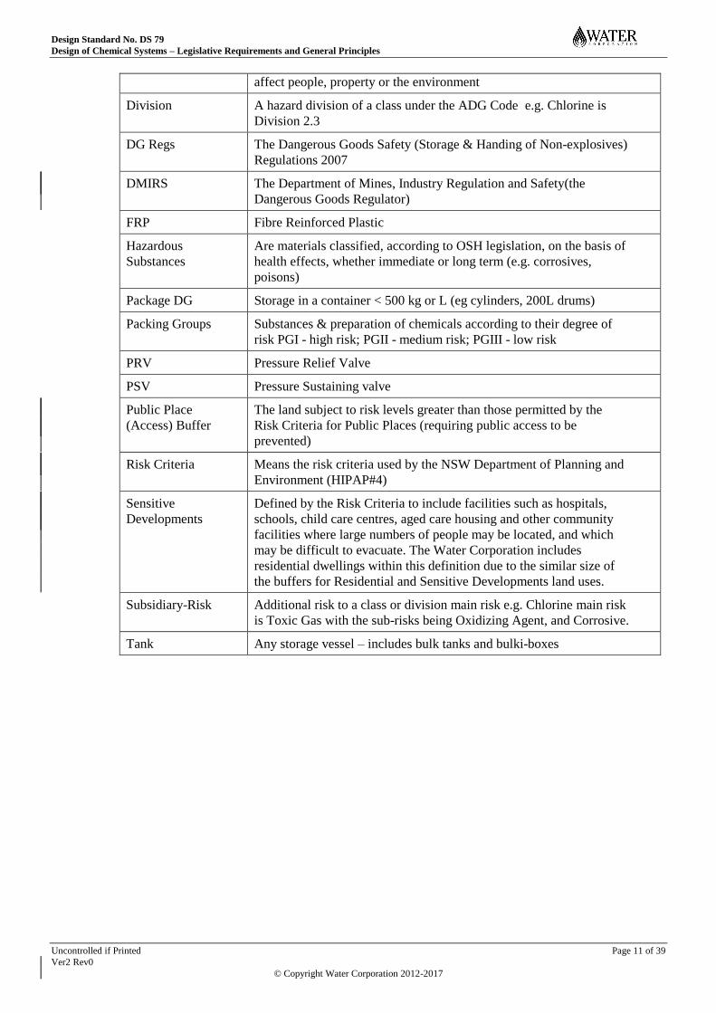
affect people, property or the environment
Division A hazard division of a class under the ADG Code e.g. Chlorine is
Division 2.3
DG Regs The Dangerous Goods Safety (Storage & Handing of Non-explosives)
Regulations 2007
DMIRS The Department of Mines, Industry Regulation and Safety(the
Dangerous Goods Regulator)
FRP Fibre Reinforced Plastic
Hazardous
Substances
Are materials classified, according to OSH legislation, on the basis of
health effects, whether immediate or long term (e.g. corrosives,
poisons)
Package DG Storage in a container < 500 kg or L (eg cylinders, 200L drums)
Packing Groups Substances & preparation of chemicals according to their degree of
risk PGI - high risk; PGII - medium risk; PGIII - low risk
PRV Pressure Relief Valve
PSV Pressure Sustaining valve
Public Place
(Access) Buffer
The land subject to risk levels greater than those permitted by the
Risk Criteria for Public Places (requiring public access to be
prevented)
Risk Criteria Means the risk criteria used by the NSW Department of Planning and
Environment (HIPAP#4)
Sensitive
Developments
Defined by the Risk Criteria to include facilities such as hospitals,
schools, child care centres, aged care housing and other community
facilities where large numbers of people may be located, and which
may be difficult to evacuate. The Water Corporation includes
residential dwellings within this definition due to the similar size of
the buffers for Residential and Sensitive Developments land uses.
Subsidiary-Risk Additional risk to a class or division main risk e.g. Chlorine main risk
is Toxic Gas with the sub-risks being Oxidizing Agent, and Corrosive.
Tank Any storage vessel – includes bulk tanks and bulki-boxes

Design Standard No. DS 79
Design of Chemical Systems – Legislative Requirements and General Principles
Uncontrolled if Printed Page 12 of 39
Ver2 Rev0
© Copyright Water Corporation 2012-2017
2 LEGISLATIVE REQUIREMENTS
The storage and handling of chemicals is managed through three Acts and their associated
Regulations;
1. Occupational Safety and Health Act 1984
2. The Dangerous Goods Safety Act 2004
3. The Poisons Act 1964
All chemicals that possess hazardous qualities fall within the scope of the WA Occupational Safety
and Health Act, with a subset of these falling within the Dangerous Goods Safety Act (ie are defined
as Dangerous Goods under the ADG Transport Code). A lesser number fall within the Poisons Act (ie
are classified as Scheduled chemicals in accordance with the Australian Poisons Standard 2011).
It should also be noted that the Environmental Protection Act 1986, through the Environmental
Impact Assessment process requires the risk posed by chemicals (including dangerous goods) to be
considered. This process is not covered within this standard.
The use of chemicals in contact with drinking water is covered by a Memorandum of Understanding
(MOU) between the Department of Health (WA) and Water Corporation. Schedule 7 of the MOU
outlines the chemicals that are approved for addition to drinking water. Schedule 8 covers chemicals
and procedures used to maintain water treatment and distribution systems, whilst Schedule 5 covers
materials approved for use in contact with drinking water. All new requests for chemicals to be used
which may come into contact with drinking water must be directed to Water Corporation’s Water
Quality Branch who has the process accountability for approving such chemicals.
2.1 Licensing - Overview
The Occupational Safety and Health Act 1984 does not include any requirements for licensing of
hazardous substances as it just sets out requirements for the design of systems and the handling of
chemicals.
The Dangerous Goods Safety Act 2004 does include requirements for licensing of Dangerous Goods
above defined quantities (known as Manifest quantities) in accordance with Schedule 1 of the
Dangerous Goods Regulations. The quantities vary according to the type of chemical. A Dangerous
Goods license is site specific and is required before site construction commences. The Dangerous
Goods Safety Act calls upon the requirements of the Dangerous Goods Safety (Storage & Handing of
Non-explosives) Regulations 2007 and various Australian Standards.
The Poisons Act 1964 requires a permit to be obtained, for Scheduled chemicals, before they can be
stored on site. Each Water Corporation Region, Branch or Alliance maintains a Poisons Permit that
they simply add new additional sites to (or amend the quantities at existing sites).
2.2 Dangerous Goods Licensing - Requirements
2.2.1 Major Hazard Facility Notifications
As part of Dangerous Goods Licensing, a proponent is required to submit a Major Hazard Facility
(MHF) Notification to the Dangerous Goods Regulator, the Department of Mines, Industry
Regulation and Safety (DMIRS), where a site is intended to store Dangerous Goods in excess of the
Major Hazard Facility threshold. Liquified Chlorine Gas is currently the only MHF Schedule
chemical used by WC and its threshold is 2.5 tonnes.

Design Standard No. DS 79
Design of Chemical Systems – Legislative Requirements and General Principles
Uncontrolled if Printed Page 13 of 39
Ver2 Rev0
© Copyright Water Corporation 2012-2017
Design Managers shall prepare a Major Hazard Facility Notification, in conjunction with the Senior
Principal Engineer, Water Treatment, at the end of Concept Design Stage. This will entail
developing a chlorine buffer drawing and possibly a Quantitative Risk Assessment.
2.2.2 Dangerous Goods License Applications
The Department of Mines, Industry Regulation and Safety, requires Dangerous Goods License
applications to be developed by accredited licensing consultants, a list of whom can be found on their
website. The license application includes an Emergency Response Plan, Emergency Services Manifest
and Dangerous Goods Risk Assessment. These three documents are all prepared by the Chemical
Safety Specialists in Water Treatment section.
License applications should be submitted to DMIRS at the end of Engineering Design Stage.
Note: For sites below Manifest/Licensing quantity, Dangerous Goods cannot be brought on site until an Emergency
Response Plan, Emergency Services Manifest and Dangerous Goods Risk Assessment have been prepared.
2.3 Poisons Permits
As indicated earlier, the Poisons Act requires a permit to be obtained, for Schedule 7 chemicals,
before they can be stored on site. Currently, the only Schedule 7 chemicals used by the Water
Corporation are Chlorine and Fluorosilicic Acid – these are found in Schedule 7 of the Australian
Poisons Standard 2011. The Design Manager should arrange with their Chemicals Advisor for the
existing Poisons Permit to be updated for the Region, Branch or Alliance in question.

Design Standard No. DS 79
Design of Chemical Systems – Legislative Requirements and General Principles
Uncontrolled if Printed Page 14 of 39
Ver2 Rev0
© Copyright Water Corporation 2012-2017
3 WATER CORPORATION REQUIREMENTS
During the design process, Water Corporation has two internal requirements concerning the storage of
chemicals, as follows;
Procurement Branch (Chemical Contract Officer) should be notified by the Design
Manager of the chemical quantities being proposed for a new or upgraded site before the
end of Concept Design Stage,
A chlorine/ammonia buffer drawing should be developed by the Design Manager in
conjunction with the Senior Principal Engineer, Water Treatment before the end of
Engineering Design Stage.
A listing of Legislative and Water Corporation Requirements can be found in Appendix 1:
Design Manager Actions.
3.1 Estimating Chlorine Buffers
As per the requirements of S334 Defining, Securing, Protecting and Managing Chlorine Buffers, there
is a need to identify the buffer requirements of chlorine facilities. DMIRS uses the risk criteria also
used by the NSW Department of Planning and Environment (HIPAP#4) to determine whether the risk
posed by a chlorine facility is acceptable. The risk criteria include consideration of a number of land
use types, as follows;
Sensitive Developments
Residential Developments
Commercial Developments
Public Access
Industrial Developments
Quantitative Risk Assessments are undertaken to determine the levels of risk identified to be of
interest to the risk criteria, and have shown the Commercial Developments buffer and Public Access
buffer to be minimally separated (ie about 20m at most). Additionally, the incidence of the
Commercial Developments buffer being critical to buffer planning is rare and the Industrial
Developments buffer is not critical to buffer planning as the Water Corporation has a policy of
purchasing the Public Access buffer, which includes the Industrial Developments buffer. Hence, the
Corporation’s buffer planning focuses on the following three land uses;
Sensitive Developments
Residential Developments
Public Access
In remote regional locations, where land use is farmland and unlikely to change, the Water
Corporation purchases the Public Access buffer and is required to notify surrounding land owners of
the Residential Developments buffer. In locations where land use might change, however, Water
Corporation policy (as per S334) is to secure the Sensitive Developments buffer in some way. This is
organized by the Project Manager and Procurement and Property Branch.

Design Standard No. DS 79
Design of Chemical Systems – Legislative Requirements and General Principles
Uncontrolled if Printed Page 15 of 39
Ver2 Rev0
© Copyright Water Corporation 2012-2017
The Water Corporation maintains a matrix of Quantitative Risk Assessments for internal use, which
covers a variety of chlorine storage configurations and notes the buffer requirements for each. Most
chlorine storage configurations are covered by the matrix, although occasionally a Quantitative Risk
Assessment will need to be undertaken by a consultant for a specific site configuration. The Senior
Principal Engineer, Water Treatment maintains a preferred consultancy arrangement with a specialist
consultant and will organize any site specific Quantitative Risk Assessment required.
3.2 Ammonia Buffers
It should be noted that the Risk Criteria also applies to ammonia buffers. Where gaseous ammonia is
stored onsite (typically for chloramination), the site buffer sought shall take its risk impact into
account (the ammonia risk levels are cumulative with the chlorine risk levels).
3.3 Buffer Risk Mitigation Options
Risk mitigation options might be considered to either reduce chlorine or ammonia buffers, or to
reduce the consequences of a leak. The following are typical reasons for incorporating risk mitigation
measures over and above standard designs;
Chlorine or ammonia buffer is marginal with respect to meeting Risk Criteria
Chlorine or ammonia buffer does not meet the Risk Criteria
Community facilities or businesses are in close proximity to a chlorine or ammonia facility
and the emergency response time is greater than 30 minutes
Sensitive developments are in close proximity to the facility even though the buffer is
adequate (ie meets risk criteria).
Typical risk mitigation options include:
Inclusion of emergency shutoff devices (ESDs). These are now are mandatory requirement
for all WC chlorine facilities.
Use of a containment building
Use of a containment building incorporating a truck drive through
Relocation of the chlorine or ammonia facility, or substitution of chlorine with sodium
hypochlorite or electrochlorination
Inclusion of a solid media emergency gas scrubber
Section 5 of DS70-01 contains additional information concerning chlorine containment buildings.

Design Standard No. DS 79
Design of Chemical Systems – Legislative Requirements and General Principles
Uncontrolled if Printed Page 16 of 39
Ver2 Rev0
© Copyright Water Corporation 2012-2017
4 DESIGN PRINCIPLES – RISK MANAGEMENT
The design of chemical facilities is not just about satisfying the requirements of the DG Regs and
Australian Standards. It is about Risk Management. The OSH Regulations make this particularly
clear (eg Hierarchy of Risk Controls), with designers now having to provide Safety in Design reports,
which are intended to brief the construction, commissioning, operations and maintenance personnel
about hazards associated with the design during their activities.
The following section addresses the general design principles associated with corrosive chemicals –
chlorine is specifically addressed through the DS70 design standards.
4.1 Housing of Corrosive Chemical Facilities in Buildings
From a risk management perspective, housing of chemical facilities in buildings has the following
advantages:
It provides an additional level of separation of the hazardous chemical from staff
(operations and maintenance) and visitors to site;
It provides an additional level of security; and
Protects equipment from UV degradation, which might initiate early failure.
Reduces the impact of extreme ambient temperature fluctuations that could cause
operational problems (eg hypo – loss of strength, caustic – freezing).
Buildings do, however, have a substantial capital cost. This cost must be weighed though against the
costs of a suitably engineered outdoor facility with a risk profile acceptable to the Asset Delivery
Representative.
Note 1: An outdoor facility will not have the same risk profile as a housed facility because of the advantages that a
building provides, but, if it has been determined to be the most economical solution, it must be engineered with an
acceptable risk profile in line with the User Requirements.
Risk treatment of outdoor facilities has historically been poorly undertaken and under-costed. It has
also tended to rely on operations/maintenance, PPE Use and Administrative Controls, which do not
conform to the risk management philosophy of the OSH Regulations Hierarchy of Risk Controls.
Note 2: Housed chemical facilities also include the benefit of excluding rainfall from the bund, which eliminates the
need to size the bund with additional capacity for rainwater and the capital and operating costs associated with
regularly having to keep the bund level low.
Note 3: Housed chemical facilities also include the benefit of shielding chemicals from extreme temperature
fluctuations that could cause operational problems (eg hypo – loss of strength, caustic - freezing).
4.2 Design Features of Housed Chemical Facilities
4.2.1 Ventilation
The building ventilation system design shall comply with the requirements of AS1668 and/or any
other relevant Australian Standard. Chemicals emitting fumes classifiable as “Type Effluents” shall
be provided with a combination of natural and mechanical ventilation.
Design Standard No. DS 79
Design of Chemical Systems – Legislative Requirements and General Principles
Uncontrolled if Printed Page 17 of 39
Ver2 Rev0
© Copyright Water Corporation 2012-2017
4.2.2 PPE and First Aid Storage
The facility shall include generous room to store the PPE and first aid equipment that is required for
use in the chemical store and/or dosing room. This space may be provided in a room such as a control
room, but, it shall be in close proximity to the chemical store and/or dosing room.
4.2.3 Personnel Doors
The location of access doors to the room shall be selected in order to maintain the required separation
and segregation distances outlined in the Western Australian Dangerous Goods Safety Act 2004 and
its associated regulations and codes of practice. Consideration should be given to the potential
inclusion of exit only doors where personnel undertaking activities may not be able to access the usual
route of entry/exit.
Personnel doors shall be designed to meet the required fire rating and shall be fitted with crash-bars
for use as emergency exits. They shall open outwards and the travel path of the doors shall not be
restricted by external features on the building or any other structure. External doors shall be metal-
faced to provide weather resistance but insulated at the same time to prevent heat transmission into
the Hypo storage room. They shall have pull handles and foot bolts for holding them in the open
position when required. Hydraulic operated door anti-slam closer/dampener shall be provided for
each door leaf. Appropriate signs shall be fitted on the doors.
4.2.4 Layout and Design
The internal layout shall be as uncluttered as possible with all piping to be located either around the
periphery of the building, or attached to the ceiling, to give a smooth tidy arrangement which leaves
adequate access to all components. The internal walls of the room shall be designed to minimise the
number of protrusions and thereby provide as much flush wall space as possible to facilitate running
of piping and cable trays around walls. The piping shall also be appropriately located to allow easy
access to equipment and pipes, and facilitate unobstructed cleaning of the work areas. Ramps over
the drops in floor levels should be included at appropriate locations for easy moving of equipment in
and out of the building.
Commissioning Plan Information
In response to recent devastating bushfires, doors, windows and ventilation openings shall be
designed to better withstand bushfire attack in accordance with the recently updated AS3959:2009
incorporating Amendment No. 1 (Nov 2009), No. 2 (Feb 2011) and No. 3 (Nov 2011).
The building shall also be designed to exclude wildlife, insects and vermin. Measures shall include
door seals, tropical midge mesh on ventilation openings, and brush-ware around the edges of the roller
shutter to impede ingress of insects through the doorway when the roller shutter is in the closed
position.
The building shall be designed so that storage tanks can be removed and replaced, by using either
removable wall panels, or having a roof specially designed with a lift-out section such that the
structure retains integrity when the roof section is removed. For facilities with two or more storage
tanks, the design shall allow for replacement of any tank while the others remain in operation.
4.3 Design Features of Outdoor Chemical Facilities
As noted in section 4.1, outdoor facilities are subject to a number of issues that need to be addressed
through substitution, elimination or engineering controls. The design of outdoor facilities must not
rely on operations/maintenance, PPE Use and/or Administrative Controls as these do not conform to
the risk management philosophy of the OSH Regulations Hierarchy of Controls.
Design Standard No. DS 79
Design of Chemical Systems – Legislative Requirements and General Principles
Uncontrolled if Printed Page 18 of 39
Ver2 Rev0
© Copyright Water Corporation 2012-2017
4.3.1 Consideration of Operational Activities
Consideration needs to be given to operational activities that may occur in the vicinity of an outdoor
storage, as personnel should not be reliant on PPE Use or Administrative Controls when undertaking
routine tasks – eg checking instrument readings, taking samples, moving from one area of plant to
another, etc.
Maintenance activities are normally not an issue as plant is typically taken off-line to allow work to
be performed. If this is not the case, however, then the design should incorporate risk mitigation
measures (eg dosing panel enclosures) so that personnel are not solely reliant on PPE Use or
Administrative Controls.
4.4 Lighting
Internal lighting, external entry lighting and lighting on internal roads shall be provided, all with easy
and safe access for lamp maintenance. These lighting levels and other characteristics shall be
designed so as to conform to the requirements of DS28. Internal lighting shall be on backup power
supply (eg UPS) unless specifically not required in the project User Requirements. The building shall
be equipped with internal emergency lighting that has battery backup.
4.5 Chemical Pipework
Consideration should be given to dilution of chemicals within the storage bunded area in order to
reduce the hazard that they present to personnel, but, it is accepted that process reasons can preclude
this, and that it is impractical to dilute some chemicals below hazardous levels. Regardless of whether
this occurs or not, however, all chemical pipework shall be designed with risk treatment and run in
such a way as to prevent any spillage from impacting people or the environment.
Factors that will influence the risk treatment design include:
The proximity of the chemical line/pipework to areas frequented by
operational/maintenance personnel;
The degree of hazard presented by the undiluted or diluted chemical; and
The height of the pipework, etc
Note: Some diluted chemicals still present a significant hazard in the event of a leak and so their pipework should be
subject to high levels of risk mitigation treatment.
Chemical pipework running within a bunded or containment area shall therefore be subject to the
following types of risk treatment:
Surrounded by containment piping that drains to the chemical bund sump or viewing catch
pots at low points;
Run in an enclosure (eg such as a duct) that prevents spraying of any chemical leak;
Wrapped at strategic points such as flanges, joints, bends, etc;
Run without protection where there are other controls in place (eg barriers, separation, etc).
Outside a bunded or containment area, chemical pipework shall conform to one of the following risk
treatments:
Design Standard No. DS 79
Design of Chemical Systems – Legislative Requirements and General Principles
Uncontrolled if Printed Page 19 of 39
Ver2 Rev0
© Copyright Water Corporation 2012-2017
Surrounded by containment piping that drains to a chemical bund sump or viewing catch
pots at low points;
Run in an enclosure (eg such as a compatible material duct) that prevents spraying or
leakage of any chemical leak;
Run without protection where there is minimal risk of environmental pollution or injury
arising as a result of a leak.
Dosing pump panels shall be housed in an enclosure which complies with DS79-03 Chemical Barrier
Protection Standard that allows ready maintenance access but which will prevent a chemical jet from
spraying personnel or equipment.
Commissioning Plan Information
All above ground pipework shall be painted in accordance with Water Corporation Standard DS95
(Appendix 3 Coating Specification K1). Paint on pipes located outside the building shall be UV-
resistant. Where the pipes need to be in a more aggressive environment, a chemical resistant paint
may be required. The manufacturer/paint supplier will need to be consulted regarding the suitability
of the paint on PVC if it is used.
Chemical pipework shall be identified in accordance with S399 DG Safety Signage, Labels and
Markers.
Buried pipework or pipework installed in culverts (not exposed to UV) does not require painting, but
shall be labelled for identification purposes.
It should be noted that in some cases there may be less risk and cost in running a pipe tube within a
PE pipe, compared to running a double-contained PVC pipe. The expected life of the tube in contact
with the chemical, the length of the tube and the number of bends (a key source of risk) that a PVC
pipe might have to navigate will all be key inputs into the option assessment.
4.6 Materials of Construction Issues
Materials of construction need to also take into account the impacts of fumes emanating from the
chemical in question, as well as, its properties when undergoing dilution (including heat of dilution).
Water Corporation mechanical design standards (DS30-DS35) shall be complied with where
applicable.
4.7 Dosing System Considerations
4.7.1 Chemicals Prone to Gassing
The design of dosing systems for chemicals that are prone to gassing shall take note of the de-gassing
provisions contained in DS73 Sodium Hypochlorite design standard.
4.7.2 PSV and PRV Settings
PSV’s shall be set a minimum of 10m head above that of the dose point.
A pressure gauge shall be provided in the vicinity of any PSV’s or PRV’s to allow ready checking of
their performance. This is particularly important where a PSV may be located some distance from the
dosing panel.

Design Standard No. DS 79
Design of Chemical Systems – Legislative Requirements and General Principles
Uncontrolled if Printed Page 20 of 39
Ver2 Rev0
© Copyright Water Corporation 2012-2017
Commissioning Plan Information
The pressure setting of PSV's and PRV's shall be recorded on their valve tags.
4.8 Pipework Testing
Commissioning Plan Information
All pressure pipework shall be hydrostatically pressure tested in accordance with AS 4041 before
being commissioned. Unless specified otherwise the pipework should be tested to 1.5x the
maximum design pressure. Care shall be taken to remove or isolate equipment from the lines which
cannot be safely tested to the same pressure as the pipework.
Design Standard No. DS 79
Design of Chemical Systems – Legislative Requirements and General Principles
Uncontrolled if Printed Page 21 of 39
Ver2 Rev0
© Copyright Water Corporation 2012-2017
5 DESIGN PRINCIPLES – STORAGE
CONSIDERATIONS FOR LIQUID CHEMICALS
5.1 Corrosive Chemical Storage Bunding
A bund, designed and constructed in accordance with the DG Regs and AS3780, shall extend beneath
the storage tank, the load-in panel (for bulk tanks) and all dosing equipment. There shall be no
penetrations through the bund wall or floor, other than the drain pipework for the bund sump. The
bund shall be separated from Protected Places and Public Places in accordance with the DG Regs and
AS3780.
Where a bund is to be located outdoors, provisions shall be made for managing the ingress of rain,
leaves and debris.
5.1.1 Bund Volume and Geometry
Bund volume shall be at least 110% of the volume of the largest tank in the bund. This calculated
volume shall not include the volume occupied by foundations and other items within the bund.
If tanks are cross connected and operated together, rather than as duty and standby, then the bund
shall be sized to hold 110% of the contents of both tanks.
The bund wall height and position relative to the chemical storage tanks shall be such that:
the bund wall shall be at least 1000 mm from any storage tank containing dangerous goods
to allow for clear access; and
no portion of the tank shall lie outside of any line drawn from the top inside edge of the
bund wall at an angle of 26.5 degrees to the vertical (this is equivalent to a rise of 2 metres
for every one horizontal metre – the tan theta/crest locus limit rule of AS3780). This is to
prevent liquid squirting over and outside the bund wall.
For facilities with more than one tank, the minimum separation distance between the tanks is 600mm
(AS3780 5.3.2.2), however for ease of access for maintenance and operation 1000mm is preferred.
The bund floor shall have a minimum slope of 1 in 50 falling towards its sump which shall be located
in a corner that is readily accessible by maintenance personnel. Note that this grade has been
deliberately selected to be greater than typical tolerances for unformed surfaces to avoid ponding.
5.1.2 Bund Sump and Valves
The bund shall include a sump of sufficient size to provide ample access and volume for
neutralisation or dilution of small spills and to hold all equipment and pipework terminations:
float valve (for wet sumps),
high level switch,
conductivity meter (need dependent upon chemical),
overflow lines,
drain lines, etc

Design Standard No. DS 79
Design of Chemical Systems – Legislative Requirements and General Principles
Uncontrolled if Printed Page 22 of 39
Ver2 Rev0
© Copyright Water Corporation 2012-2017
A float operated water supply valve (if required) shall maintain a fixed water level in the sump. As
this valve is crucial for the effective functioning of the wet sump, the float operated valve must be of
durable, high quality construction. The robust, heavy duty type valve shall have a reliable control
mechanism that requires minimal maintenance. Valve components shall be constructed with materials
that are corrosion-resistant and suitable for the chemical environment.
The sump shall be adequately sized to house all necessary equipment and pipe entries. From past
project experience the recommended minimum sump dimensions are: 1200 long x 800 wide x 600
deep. This arrangement provides adequate volume for spill neutralisation and sufficient water depth
for operation of the float valve and immersion of the conductivity sensor. Clear access for
maintenance of the valves and equipment located in and adjacent to the sump shall be provided.
A DN50 PVC drain outlet pipe positioned flush with the floor of the sump shall lead to an exterior
valve pit outside the building where a DN50 motorised bund outlet valve and two manual isolation
valves are located. The recommended minimum sump dimensions are 1200 long x 800 wide to enable
easy access for the installation and maintenance of these valves. The electrically-actuated valve shall
be operated from a local operator interface panel (LOIP) and shall be interlocked with sump
conductivity to prevent inadvertent discharge of chemical from the bund. An override will be
available from the LOIP to allow this interlock to be overridden by the operator on site, only once
they have confirmed that the contents of the sump are safe for disposal to the sludge drying beds.
A motorized three way isolation valve shall be used to direct the bund contents to either a waste
holding tank or the sludge drying bed/drainage system. Normally the valve is closed to prevent the
discharge of chemical. However, when the contents of the internal bund sump are known to not be
contaminated with chemical, such as may be the case during a routine bund hose down, the valve is
operated to direct this uncontaminated water to the sludge drying beds or drainage system.
This exterior valve pit shall have a removable FRP gridmesh cover, and its purpose is to allow ready
access to the bund outlet valve and isolation valves when the bund is full. If the outlet valve were
located within the internal bund sump it would be difficult to access the valve as the sump is kept full.
These valves shall be supplied with securely-supported extension spindles and handles located just
below the FRP gridmesh cover to allow manual operation without sump entry. The valve tag numbers
along with open and close positions shall be clearly marked on each valve. A simple and concise
description outlining the purpose of each valve shall be mounted on a small sign adjacent to each
handle to assist with correct valve identification and operation.
Any rain water collected in this external sump will be directed to the load-in apron sump by a DN100
PVC drain line. An additional collection chamber, sump pump and delivery line shall be provided if
gravity flow to the drying beds and waste holding tank cannot be achieved. This system can be
common with other compatible chemical bund sump drains.
5.1.3 Bund Linings and Coating
A chemical proof (or resistant) coating shall be provided for the bund. Coatings for concrete bunds
shall comply with Water Corporation Coating Specification CR5. To achieve effective water-tight
sealing of the bund, proper application of coatings is essential especially around pipes and fittings
which pass through the bund wall or floor. Strict specifications for products to be used and the
methods of application should be in place to ensure that this is achieved.
The bund floor, sump, walls (and building walls where these are within the crest locus limit of the
tank and therefore acting as a bund wall) and tank plinths shall be coated. The grouting at the
interface between supports or equipment shall also be coated to the same standard as the rest of the
bund. The floor coating system shall incorporate a non-slip finish.

Design Standard No. DS 79
Design of Chemical Systems – Legislative Requirements and General Principles
Uncontrolled if Printed Page 23 of 39
Ver2 Rev0
© Copyright Water Corporation 2012-2017
Full PVC lining with joined PVC sheet is very expensive and not believed necessary given the vast
array of relatively inexpensive polymer and epoxy based acid resistant surface coatings now available.
Experience has also shown that PVC bunds can be susceptible to cracking at the joints.
Past experiences with many of these coatings have demonstrated some deficiencies where the bund
was still not sealed (water tight) following application. Leaks have been experienced in the past at the
jointing between the floor and wall, and around any pipe penetration through bund wall, so this is an
area that needs design and construction attention.
Commissioning Plan Information
A 24 hour hydrostatic leak test shall be conducted on a bund prior to the filling of its associated
storage tank(s) with chemical.
5.2 Platforms and Stairways
An FRP gridmesh platform is to be provided over the bund to give access around the tank if there are
any valves in the bund that require operation. Sufficient gridmesh area is required to accommodate
the load-in and dosing panel(s) and associated equipment. The height of the platform is to suit the
height of the load-in connection (refer to section 5.4.3 for further detail). All platforms and stairways
shall be designed in accordance with DS30-02, DS100, AS1170.1 and AS1657 and shall have the
necessary kickplate and handrails. All structural components of the floor, stairs and handrail system
shall also be FRP.
There shall be a stairway from the platform down to the bund floor for access to the bund sump. All
stairways from platforms where work might be undertaken (eg on nearby instruments, valves etc)
shall be equipped with automatic self-closing gates. The gates shall close in such a way as to prevent
people from falling down stairs. Stairs and platforms shall be sized to accommodate the movement of
personnel wearing fully encapsulated protective suits and SCBA sets.
The FRP grating selected for the platform shall:
a) Be resistant to the chemical;
b) Be moulded type with square mesh pattern to provide bi-directional strength;
c) Have a non-slip grit top surface;
d) Have a layout which enables access to pipework, valves and equipment by incorporating readily
removable sections;
e) Be fastened in place using 316 SS clips to prevent sliding and overturning; and
f) Have any shop or field cuts coated with resin to provide maximum corrosion resistance.
Various grades of FRP grating are available, so it is important to ensure that the FRP grating selected
and supplied for a chemical storage room is resistant to the chemical and its fumes. Each
manufacturer has its own means of designating grating types, whether it be specific colours to indicate
acid resistance or cast-in identification threads, so suitability will need to be confirmed with the
individual FRP manufacturer when a grating is being considered for use.
The design should minimise the number of valve spindles to be extended above grating level and
provide cutouts to allow use of a tool to operate below the grating valves (operators shall not be
required to have to kneel and/or extend their hands below grating level. Cutouts shall not create a
tripping hazard or obstruct access/egress ways. Where cut outs are required in the FRP grating, for
raised valve spindles or to accommodate equipment, then proper strengthening and support of the
modified grating shall be carried out by qualified designers and installers to ensure its integrity is not
undermined. The open hole in the grating that results from the cut out shall be covered with a

Design Standard No. DS 79
Design of Chemical Systems – Legislative Requirements and General Principles
Uncontrolled if Printed Page 24 of 39
Ver2 Rev0
© Copyright Water Corporation 2012-2017
removable cut-to-shape FRP grating panel securely supported and clipped. All modification work to
the grating shall comply with the relevant OSH requirements for safe access of Grid Mesh Landings.
Equipment and valve spindle end shall not protrude out of the FRP grating where it could pose a
tripping hazard.
The design of the FRP platform supports shall:
a) Meet the design loading requirements;
b) Allow for access to pipework and equipment;
c) Take into account the direction of fall across bund floor; and
d) Keep the number of concrete embedment’s to a minimum.
Structural FRP members shall be secured to the concrete floors and walls using 316 SS chemical
anchors. The concrete to base plate interface shall be grouted (30 mm nominal) to prevent liquids and
debris collecting underneath. Unless resistant to the chemical, the grout shall be coated to the same
standard as the bund.
5.3 Accessibility
A minimum clearance of 1m shall be provided around all equipment with consideration given to a
greater clearance where maintenance activities require it.
5.4 Bulk Delivery Requirements
5.4.1 Delivery Sizes
Delivery truck sizes for project locations shall be checked with Procurement Branch (Chemical
Contract Officer).
The power supply, delivery hose length and turning circle requirements for the proposed delivery
truck shall be identified early in engineering design stage – Procurement Branch (Chemical Contract
Officer) should again be contacted to obtain these details.
Where required, a permanently mounted, external weatherproof electrical power outlet conforming to
the following specifications shall be provided for truck mounted pumps:
a) Power outlet to be located away from the delivery hose connection point but within 7.5 metres
of the road tanker;
b) IP56 rated combination switch and 4-pin plug socket for 3-phase, 415 Volts, 50 Hz at 20 Amp
rating with earth leakage protection (eg. Clipsal 56 Series);
c) Equipment rated for starting a “x” kW motor;
d) Earthing point close to plug outlet and earth leakage protection;
e) The installation is to be in accordance with AS 3000 and power supply authority regulations
including appropriate labelling.
The power outlet shall incorporate a device to cut off the power supply when the storage tank high
high level alarm is initiated.
Early in the design phase the designers shall confirm what type of deliveries will be received and
design the load-in facilities accordingly.

Design Standard No. DS 79
Design of Chemical Systems – Legislative Requirements and General Principles
Uncontrolled if Printed Page 25 of 39
Ver2 Rev0
© Copyright Water Corporation 2012-2017
5.4.2 Load-in apron
A 200 mm thick reinforced concrete load-in apron shall be provided adjacent to the chemical storage
room and be 4.5m wide. The length is dependent upon the delivery truck type, although the truck cab
does not need to be contained within the load-in apron. The apron shall be graded to a sump and shall
have a small trafficable lip 30-50mm in height above the roadway around the perimeter for the
containment of spills. The load-in apron shall be graded to a sump from where its contents drain to
either a soakwell/ site storm water drainage, or a waste holding tank via an actuated 3-way valve.
Under normal conditions, this valve is opened to discharge to the soakwell/site drainage so that
rainwater is not collected on the apron. During a delivery it is part of the tanker truck driver’s
procedures to open the door in front of the load-in panel. At sites where the security system is not
linked to the load-in system, the opening of this door will automatically initiate the 3-way valve to
open to the waste holding tank (and close to site drainage) in anticipation of any potential spillage. At
the end of the load-in process, the door to the load-in panel would be closed activating the switch to
revert the valve back to its normal state of ‘open to site drainage’ and ‘closed to the waste holding
tank’
The actuated 3-way valve shall have limit switches to indicate valve position on the HMI, OIP and
load-in panel displays. It shall have manual override with securely-supported extended spindles all
housed in a valve pit with removable cover. In the event of valve failure or power outage, the valve
shall automatically open to the waste holding tank and close to site drainage.
The sump shall be fitted with a suitable level switch to provide warning when the content in the sump
has reached a set high level. The sump high level alarm shall be annunciated on the load-in panel and
on the OIP/HMI.
For multi-chemical facilities, the designer should consider the risk due to spills of incompatible
chemicals (eg. acid and sodium hypochlorite) mixing in the waste holding tank and associated
pipework.
Road access to the load-in apron shall be designed to include a drive through route. If this is not
possible, as may be the case on brown field sites, a turning circle shall be incorporated. This is to
enable the delivery truck to be driven clear of the facility without the need to reverse1.
A safety shower shall be provided at apron level between 2m and 7m from the transfer point,
primarily for the use of the delivery driver, and a 600 mm wide clear access route to this shower shall
be maintained at all times. Any platform or stairs projecting onto the load-in apron shall be designed
so that access to the safety shower is not restricted, especially when the truck is parked up for
unloading. See also section 5.8.2.
5.4.3 Load-in Panel and Transfer Point
Chemicals are transferred from the delivery truck into the storage tanks via a transfer point on the
load-in panel. This load-in connection shall meet the following requirements:
It shall be located at a height such that the flexible hose will drain back to the delivery
tanker (2.2m height above road level is typical, but, should be checked for the chemical
tanker in question).
1 AS3780 Cl 5.5.7 (d) iii requirement.
Design Standard No. DS 79
Design of Chemical Systems – Legislative Requirements and General Principles
Uncontrolled if Printed Page 26 of 39
Ver2 Rev0
© Copyright Water Corporation 2012-2017
It shall be located at a safe height for connection and disconnection - 1m above
floor/platform level is recommended.
It shall be located at least 5m from any protected places or the plant boundary2.
It shall be positioned on a 45o angle for ease of connection and to prevent excessive
curvature of the hose (Note: Where a low level connection point has been permitted by the
Principal Engineer Water Treatment, then a 90o angle shall be used instead).
The 45deg bend shall be fitted to the panel using a flanged fitting, for ease of replacement
(glue not to be used). The 45 deg bend and camlock are high wear components and are
regularly damaged or broken-off. For ease of replacement, a flanged joint shall be used to
connect the 45° fitting to the piping instead of solvent welding. The flanged joint shall be
wrapped to minimise the impact of a gasket failure. Screw fittings shall not be employed in
accordance with AS3780.
It shall have a safety shower and eye wash compliant with DS79-02, located between 2 and
7m from the transfer point and on the same level (no stairs or other obstacles along route).
It shall be a type A camlock coupling with matching type DC dust cover (polypropylene is
typically used as it is compatible with most chemicals, but, this should be confirmed by the
designer). The coupling size and configuration to be used shall be confirmed with
Procurement Branch (Chemical Contract Officer).
It shall have a valved drip leg, which is used to check that the delivery line has drained
completely prior to disconnection of the hose.
All flanged fittings shall be wrapped to minimise the impact of a gasket failure.
To meet these requirements the load-in panel shall be located on an elevated platform. The load-in
panel shall be located inside the bunded area. Where possible the FRP gridmesh covering the bund
within the chemical room shall also be at the same level as the elevated platform. For buildings, a
roller shutter door complete with thermal insulation shall be provided to gain access to the load-in
panel for the tanker hoses. Outside the building, there shall be a continuation of the platform in front
of the roller shutter door, and a stairway shall give access to this external platform from ground level.
Drawing GT36-070-083-1 provides an illustration of this arrangement for information.
The load-in panel shall be constructed from PVC sheet (nominally 12 mm thick) with FRP frame and
supports. It shall have a drip tray which runs the full length of the panel and extends well clear of the
valves and transfer point mounted on the panel to collect any drips. The tray shall have additional
side and bottom supports to prevent cracking of PVC welds due to the weight of the hose and
operator. The front of the tray shall have a rolled over reinforced edge to act as an intermediate
support for the transfer hose. The drip tray shall be graded towards a drain that is piped to the bund
sump.
Along with the camlock, the load-in panel shall have the following valves and equipment mounted on
it:
2 AS3780 Cl 5.5.7 (c) requirement.

Design Standard No. DS 79
Design of Chemical Systems – Legislative Requirements and General Principles
Uncontrolled if Printed Page 27 of 39
Ver2 Rev0
© Copyright Water Corporation 2012-2017
tank filling line isolation valves;
drip leg valve;
large sized tank level indicators;
high level visual alarms;
high high level visual and audible alarms;
alarm acknowledge pushbuttons;
manual alarm (light/siren) test pushbutton; and
tank/bund pump out connection point;
load-in apron sump drain valve position indicator lights;
load-in apron sump high level indicator light;
a drip tray.
The tank/bund pump out connection point is usually a DN50 type B or D polypropylene camlock
coupling with matching type DP dust plug which is used to remove chemical from the bund sump or
directly from the tanks in the event of a significant spill or for maintenance. A valved water inlet point
for flushing and priming of the pump-out piping shall be also provided.
The displays, lights and sirens shall be mounted on the load-in panel so as to be as far apart as is
practical from the load-in point in order to minimise corrosion of the instrumentation. The manual
alarm (light/siren) test pushbutton is provided so operators and maintainers can simply and routinely
check alarm light and siren operation without having to first generate or simulate an alarm condition.
Similar to the safety showers, the alarm light and siren should be tested every time before unloading
chemical into the tanks.
The digital readout display of the tank level indicators shall be clearly legible to the delivery driver
during unloading, who would likely be standing next to the transfer pump control on his truck a few
metres away. The digital readout display shall therefore have a minimum character height of 38 mm
with a sunshade fitted on top to prevent glare.
All valves and equipment mounted on the panel shall be mounted at an easily accessible level (no
higher than 1.8m above floor level is preferred) and shall be clearly labeled with an engraved stainless
steel tag number and functional description e.g. VA83110 TANK 1 FILL VALVE. Other signage
which shall appear on the load-in panel includes the maximum fill level label.
The purpose of the maximum fill level label is so the Operator and Delivery Driver can check that
there is sufficient storage space in the tanks to accept a whole delivery load prior to commencement
of the unloading. The units used on the maximum fill level label should match the units used on the
tank level indicators, which should both match the units used on the delivery docket. Some suppliers
require the units to be in tonnes whilst others require kL. The units required should be checked with
Procurement Branch (Chemical Contract Officer).
All pipework and connections shall be rigidly fixed by pipe supports fastened to the load-in panel.
All fixings on the panel shall be 316 SS.
An example of a load-in panel arrangement illustrating these requirements is shown in drawing GT36-
070-083-09.

Design Standard No. DS 79
Design of Chemical Systems – Legislative Requirements and General Principles
Uncontrolled if Printed Page 28 of 39
Ver2 Rev0
© Copyright Water Corporation 2012-2017
5.5 Bulk Storage Systems
5.5.1 Storage Tank design
The choice of storage tank material shall be based upon the whole of life cost, based on a design life
of 20 years. GRP tanks shall comply with SPS498. HDPE tanks shall comply with SPS497. Other
tank materials shall comply with a relevant design code/standard. All tanks shall comply with the
process requirements set out in the following sections.
Consideration shall be given to the operational and maintenance benefits of using two tanks instead of
one larger tank. Storage tanks shall have a storage capacity of at least 2 weeks during peak.
Each tank shall include as a minimum the following fittings:
one (1) flanged scour outlet nozzle either on the bottom of the tank, or the side if provision
is made to ensure that the scour can drain the entire tank – eg inclusion of a false floor;
one (1) flanged tank overflow outlet nozzle with overflow pipework supports. The invert
level of this outlet shall be specified;
one (1) flanged tank fill point inlet nozzle on the tank lid;
one (1) flanged process outlet nozzle on the side of the tank (to supply chemical to dosing
panels);
one (1) flanged tank vent nozzle connection in the tank lid;
two (2) flanged nozzles, one vertically in line with the other, on the side of the tank (for
mounting of a magnetic level gauge);
sufficient lifting lugs;
one (1) flanged nozzle on the side of the tank for connecting to a pressure transmitter;
one (1) flanged side entry inspection port of diameter 300mm, to allow camera based
inspection of the tank interior or entry of a hose or flushing purposes. The inspection port
needs to be airtight when closed. (Not required for tanks below 4kL in capacity).
Each tank shall have an integral non-removable roof. The base of the storage tank should be graded
towards the scour outlet where practicable to ensure that the tank can be drained completely. A false
floor may be required to achieve this requirement.
Each tank shall be designed for the following criteria:
a) Operating & Design Temperature: range appropriate to the site
b) Operating & Design Pressure: atmospheric and hydrostatic

Design Standard No. DS 79
Design of Chemical Systems – Legislative Requirements and General Principles
Uncontrolled if Printed Page 29 of 39
Ver2 Rev0
© Copyright Water Corporation 2012-2017
c) Roof Live Loading: 1.25kPa
Adequate fixings at the base of each tank shall be provided to resist all seismic and wind loads as
appropriate for the area.
All nozzles shall be flanged, reinforced and of size DN50 minimum, except the overflow nozzle
which shall be at least 1.5 times the filling line diameter of the inlet line, so the minimum size of this
nozzle shall be DN803. In accordance with DS31-02 all flanges shall be Class 14/16 to AS 4087,
unless a different flange standard has been adopted for the site for consistency. All flange bolt holes
shall straddle the centre line.
All nozzle isolation valves shall be hard flanged to the tank nozzles and shall be sized according to the
respective nozzle flange size, not the outgoing pipe size if it happens to be smaller than the nozzle.
Ensuring no other fitting between each isolation valve and the tank minimises the risk of potential
leakage on isolation.
The designer should provide drawings to the tank supplier, which clearly shows the desired location
and size of all connections and fittings on the tank(s).
A permanently affixed corrosion resistant compliance plate shall be provided on the outside of the
tank4. This plate is best located at eye level and positioned so it can be read without stepping down
into the bunded area.
The characters shall be at least 5 mm high and it shall contain the following information:
Manufacturer’s name or Registered Trademark
Date of Manufacture (Year of completion)
Serial Number
Tank Identification number or Tag Number
Capacity (Volume kL and Weight kg)
Design pressure and temperature
Design liquid specific gravity
Material of manufacture and grade
Design Code/Standard
3 AS3780 Cl 5.7.7 (b) requirement.
4 AS3780 Cl 5.7 requires certain information concerning tank details to be available to a DMIRS inspector.
Design Standard No. DS 79
Design of Chemical Systems – Legislative Requirements and General Principles
Uncontrolled if Printed Page 30 of 39
Ver2 Rev0
© Copyright Water Corporation 2012-2017
Commissioning Plan Information
Prior to delivery to site all tanks shall be hydrostatically tested using clean water filled to the
overflow level at the workshop. The full static head is to be held for a minimum of 12 hours. Once
installed, the tanks should be hydrostatically tested again to check for any damage which may have
occurred during transportation or installation.
All tanks shall be transported to site with blind flanges fixed to all nozzles to prevent dust, moisture
and vermin entering vessels.
If a crane is required to install PE & GRP tanks then soft sling rigs shall be used on the shackles so
as not to cause damage.
Note1: SPS498 contains greater detail on packaging, transport, installation and testing.
Note 2: For some chemicals such as 98% Sulfuric Acid for which water testing may be problematic,
this requirement should be replaced by an alternative quality assurance method.
5.5.2 Tank Plinth
A concrete plinth or tank stand shall be provided for each storage tank so that its base is at least above
the 110% bund fill level. The bund floor shall be designed to support the tank plinth or stand with a
tank full to the top of its wall.
The benefits of an elevated plinth include the following;
Tank valves and associated control cabling are precluded from inundation,
Associated dosing pumps are provided with a guaranteed minimum net positive suction head
and can therefore be mounted at bund wall height.
5.5.3 Tank Level Measurement
(Pressure transmitters are currently recommended but radar transmitters are being investigated).
An externally mounted pressure transmitter shall be provided to measure chemical level in each
storage tank. The signal from the pressure transmitter shall be used to calculate the amount of
chemical in the tank and to generate high level and low level alarms. This quantity shall be displayed
locally at the load-in panel as well as on the Local Operator Information Panel and Human Machine
Interface. The units used to indicate tank level on the Local Operator Information Panel and Human
Machine Interface can be either %, metres, litres or tonnes. The operators should decide which units
are to be used on the Local Operator Information Panel and Human Machine Interface based on what
is easiest for them to monitor and what units they wish to use for their alarm set points.
The high level alarm generated by the pressure transmitter is used to notify the delivery driver, via a
flashing light on the load-in panel, that a high level in the tank has been reached and there is the
potential for a tank overflow if the unloading operation is not terminated. The low level alarm
generated from this instrument is used to notify the operator that the chemical re-order level has been
reached. The low low level alarm is used as a trigger to shutdown the chemical dosing system to
prevent the dosing pump from running dry (and changeover to the standby dosing system if User
Requirements specify this configuration).
The pressure transmitter shall be installed on side mounted tank connections, complete with isolation
valves, scour valve and flushing facilities as shown on the P&ID to permit safe calibration and testing
if required. The pipework which connects the pressure transmitter to the tank shall be as short as
practicable to minimise the amount of chemical which needs to be drained away and flushed to gain

Design Standard No. DS 79
Design of Chemical Systems – Legislative Requirements and General Principles
Uncontrolled if Printed Page 31 of 39
Ver2 Rev0
© Copyright Water Corporation 2012-2017
access to the transmitter for maintenance. A diaphragm seal shall be incorporated in the pressure
transmitter installation to protect the transmitter components from contact with chemical.
Pressure transmitters are preferred to ultrasonic level detectors because:
they minimise access requirements to top of tank, thereby avoiding occupational safety and
health issues associated with working at heights;
have lower capital cost because no stairway and platform are required on top of tank; and
calibration is simple using simulated injection of pressure, whereas calibration of an
ultrasonic level device requires either manual handling of the sensor or raising levels in the
tanks to known levels.
Commissioning Plan Information
Confirm accurate calibration of the tank level indication from the pressure transmitter for the
specific gravity of the chemical to be stored in the tank.
5.5.4 Tank Magnetic Coupled Level Gauge
In addition to a pressure transmitter, each storage tank shall be fitted with a magnetic coupled level
gauge. The magnetic coupled level gauge provides a simple, continuous and positive indication of the
tank contents and thus a cross-check of the electronic transmitter. This eliminates the need to
periodically spot check the electronic indicator. It also provides a back-up level measurement device
in the event of power failure.
Each tank magnetic coupled level gauge shall be of bar graph indicator type with a red/white
(flip/flop) display. Shuttle types are not acceptable as they can lose linkage to the float. A level of
float positive buoyancy shall be acquired against the lowest possible specific gravity to ensure the
float remains in position for all normal and abnormal operations. A high high magnetic sensing level
switch shall be added to the magnetic coupled level gauge to provide protection against tank
overflow, independent of the pressure transmitter generated alarms.
Each magnetic coupled level gauge shall be plumbed to side connections on the storage tanks
complete with isolation, scour and flushing facilities (FSA standard P&ID GT36-060-083-1 provides
an example). The float chamber shall be constructed of materials suitable for contact with the
chemical.
5.5.5 Tank Inspection
Access to the top of the tank will be required for inspection purposes, but as inspection is only
required to be carried out periodically it is considered more cost effective to use purpose built
scaffolding or other temporary access methods, rather than have permanent access to the top of the
tank.
5.6 Bulk Storage System Pipework
5.6.1 Filling Line
The chemical storage tank filling lines shall be DN50 minimum. The fill line into the tank shall be
located diametrically opposite the outlet pipe to minimise the possibility of any air entrainment during
filling from interfering with the operation of the dosing pump. The fill line shall enter the tank above
the overflow level.

Design Standard No. DS 79
Design of Chemical Systems – Legislative Requirements and General Principles
Uncontrolled if Printed Page 32 of 39
Ver2 Rev0
© Copyright Water Corporation 2012-2017
Apart from a small section of fill pipework which is mounted on the load-in panel, the filling line
shall be sloped to drain back to the tank. The onboard tanker pumps used for delivery are typically
capable of pumping up to 10 m head, therefore the height of the filling line (relative to the chemical
delivery vehicles tank) should not exceed this height.
Commissioning Plan Information
Prior to the first delivery of chemical, the filling line shall be hydrostatically pressure tested in
accordance with AS 4041 to 1.5 times the operating pressure of the tanker pump and held for a
minimum of 30 mins. Written proof of this test will be requested by the chemical Supplier and shall
be made available to them.
Note: The tank shall not be subject to the test pressure as it is only rated for the static head up to the
overflow level.
5.6.2 Vent Line
Each tank shall have a vent line to allow venting of fumes during tank filling and vacuum relief during
tank emptying. The vent line shall be sized to ensure adequate air flow out of the tank during a filling
operation (including air purging) and adequate air flow into the tank whilst the dosing pump is
operating or the tank is being drained without exceeding the maximum allowable operating stresses of
the tank. As a rough rule of thumb the vent size should as a minimum be 1.5 times the fill line
diameter.
For non-hydroscopic chemicals, the vent line shall discharge outside the building at about 500 mm
above the site finished surface level, which is high enough to observe any potential dripping, but low
enough that it is unlikely that any drips will fall on personnel. The vent discharge point shall be
weather-proofed and shall be fitted with a “tropical midge wire” insect screen. Hydroscopic
chemicals need to be considered on a case by case basis as they will require a desiccant unit to be
included in order to prevent moisture being sucked back into the tank during dosing. The desiccant
unit shall be located such that it is readily accessible for inspection and can be safely maintained.
The vent outlet shall be located so that it is safe to gain access to it for maintenance purposes, and
shall be located at least 4 m away from the load-in bay so as to avoid exposing the load-in operators to
fumes during tank filling. The vent pipework shall be configured so that condensation of vapours is
directed back into the tank.
5.6.3 Scour Line
There shall be a DN50 minimum scour outlet from the bottom of each tank which is plumbed to the
bund sump, to allow complete emptying of the tank – this shall only be deviated from with the
approval of the Asset Delivery Representative.
A DN50 minimum manual valve shall be installed as close to the nozzle flange as possible to isolate
the tank in the event of an emergency or downstream leak. The instrument drain line shall tee into the
scour line in accordance with Section A on drawing GT36-070-083-05.
The scour piping shall be interconnected between the bund sump and the pump-out connection, to
enable the contents of the tank to be directly loaded to a truck without firstly dumping it into the bund
sump.
The scour valves are required to be operated without the operator entering the bund, and so the scour
outlet should be located at the edge of the FRP grating or removable cut outs shall be provided in the

Design Standard No. DS 79
Design of Chemical Systems – Legislative Requirements and General Principles
Uncontrolled if Printed Page 33 of 39
Ver2 Rev0
© Copyright Water Corporation 2012-2017
grating to access these valves. Extension spindles to bring the valve handles to a comfortable height
for ergonomic operation may be required.
Tanks shall be fabricated to allow the entire tank including any sludge that may have settled on the
tank floor to be drained out completely. Provision of a sloping false floor inside the tank is one way
to ensure complete emptying of the tank.
5.6.4 Overflow line
Each tank shall have an overflow pipe sized at not less than 1.5 times the filling line, which shall
discharge 200 mm above the bund sump. Where possible, the outlet of the overflow pipe should be
visible from the load-in point. Sturdy supports must be provided for the overflow piping to avoid
excessive loading on the tank nozzle. No valves or equipment which could potentially cause
blockages shall be installed in the overflow lines. Fuming chemicals shall include a seal pot to prevent
fumes affecting personnel in the area. Care shall be taken on the design to ensure that the sump water
cannot be drawn into the tank under any conditions.
5.6.5 Pipework Testing
Commissioning Plan Information
All pressure pipework shall be hydrostatically pressure tested in accordance with AS 4041 before
being commissioned. Unless specified otherwise the pipework should be tested to 1.5 times the
maximum design pressure.
Note: Care shall be taken to remove or isolate equipment from the lines which cannot be safely
tested to the same pressure as the pipework.
5.7 Waste Holding Tank
As discussed in the sections above, a waste holding tank with a minimum volume of 1000L5 shall be
provided at each site for the collection of chemical waste. At wastewater treatment plants, however,
for some chemicals it may be possible to return spills to the head of the plant, but, this will require the
approval of the Asset Delivery Representative.
A larger tank should be provided where other site specific considerations or risks exist – e.g. location
is near a river or other water body. The tank shall be fitted with a suitable float type level switch to
warn the operator when the waste has reached a high level and to arrange for disposal. A vent with
insect screen shall be provided for the tank.
The main purpose of this tank is to stockpile the small quantities of chemical and neutralised waste
generated in either the storage room or load-in apron during normal operational duties. When
sufficient waste is collected in the tank, a tanker truck can be arranged to pump out and transport the
5 A 1000L tank capacity would be sufficient to contain a load-in chemical spillage volume of 840L calculated from pumping at
a rate of 7L/s for two minutes before emergency shutoff. As a side note, requirement of AS3780 Clause 5.8.4.2 for capacity of
spillage control system to be the greater of 9000L or largest tanker compartment is only intended for loading of chemical into
tankers, not unloading from tankers as is the case at load-in facility. This was clarified by DMIRS in 2010 (ref. Meeting
minutes dated 3 June 2010 aquaDoc #3527812).

Design Standard No. DS 79
Design of Chemical Systems – Legislative Requirements and General Principles
Uncontrolled if Printed Page 34 of 39
Ver2 Rev0
© Copyright Water Corporation 2012-2017
waste off-site for proper disposal. If the waste holding tank is not located near to the load-in apron,
road access to the tank shall be provided for the tanker.
The waste holding tank shall be fabricated from a material suitable for the long term storage of waste
chemical, such as polyethylene, GRP or rubber lined steel or concrete, as it may be expected to hold
the waste for well over a year depending on the waste production volumes. It is normally located
below ground or at a level lower than the bund sump and load-in apron sump, so waste can gravitate
to this tank. Consideration should be given to designing the tank to withstand the ground pressure and
buoyant forces when empty
5.8 Ancillaries
5.8.1 Wash Trough
A single wash trough shall be provided for the washing of pump components, valves and other
equipment prior to removal from the chemical store room. The wash trough shall be constructed of a
material compatible with the chemical. The wash trough shall be located at a height convenient for
operator use and shall drain into the bund sump.
5.8.2 Safety Showers & Eyewash Units
5.8.2.1 Number and Location
At least two safety showers and eyewash units shall be provided. One safety shower/eyewash unit
shall be provided at ground level outside the chemical building between 2m and 7m horizontal
distance from the tanker hose connection point and the load-in panel. The second safety shower shall
be provided adjacent to the Dosing Panels, on the same level, in the storage/dosing room.
All safety showers shall comply with the requirements of DS79-02.
5.8.2.2 Safety Shower Water Supply
Potable water shall be used to supply the safety showers and eyewash units. Where a dedicated
potable water supply is not available, the safety shower supply off-take from the potable water system
on site shall be located upstream of a reduced pressure zone device (RPZD). Any water usage
connections associated with any chemical such as dilution or flushing of chemical, shall be located
downstream of the RPZD to protect the safety shower supply from potential contamination due to
backflow of chemical.
5.8.3 Hose Reels
Retractable wash down hose reels shall be provided and located such that all areas of the load-in and
storage facility can be accessed with the hose. This typically means that at least two hose reels are
required, one inside the storage room near to the dosing panels and one outside the building for use to
hose down the load-in panel and apron. Hose shall be minimum 19mm diameter and 20m in length.
5.9 Dosing Point Considerations
Where practicable, dosing points should be located above ground in order to eliminate confined space
and access/egress issues, and improve maintainability. Above ground dose points will need to be
assessed for chemical barrier protection in accordance with DS79-03.

Design Standard No. DS 79
Design of Chemical Systems – Legislative Requirements and General Principles
Uncontrolled if Printed Page 35 of 39
Ver2 Rev0
© Copyright Water Corporation 2012-2017
5.10 Bulki-Box Storage Systems
Bulki-box systems shall be designed to minimise the exposure of personnel to the chemical, whether
during filling, movement or normal operation. Designs shall not incorporate gravity decanting unless
approved by the Senior Principal Engineer, Water Treatment6.
6 FLAMMABLE MATERIALS - HAZARDOUS AREA
CLASSIFICATION
Where flammable materials can be reasonably expected to occur in normal and abnormal situations,
hazardous area classification shall be undertaken in accordance with Water Corporation Standard HA-
ST-02 “Hazardous Area Classification Standard”.
6 Water Corporation has experienced at least one significant incident involved gravity decanting.

Design Standard No. DS 79
Design of Chemical Systems – Legislative Requirements and General Principles
Uncontrolled if Printed Page 36 of 39
Ver2 Rev0
© Copyright Water Corporation 2012-2017
APPENDIX 1: DESIGN MANAGER ACTIONS
Note: The Design Manager shall ensure that each of the items listed below are addressed, although, they will
require the support of others (eg Senior Principal Engineer, Water Treatment, design consultant, project manager,
etc) to close a number of them out.
Activity Support Stage
Major Hazard Facility Notification and
Chlorine Buffer Drawing
SPE, Water Treatment Before end of Concept Design Stage
Advise Procurement Branch (Chemical
Contract Officer) of Chemical Quantities
Procurement Branch Before end of Concept Design Stage
Discuss truck sizes, turning circle and
power configuration with Procurement
Branch (Chemical Contract Officer)
Procurement Branch Early Engineering Design Stage
Obtain approval for use of chemical not
covered by WC’s MOU with Department
of Health
Drinking Water Quality Early Engineering Design Stage
Chlorine Buffer Drawing (non drum sites) SPE, Water Treatment Before end of Engineering Design
Stage
Dangerous Goods License Application,
ERP, Manifest and DG Risk Assessment
Hazardous Area Classification
Pressure Vessel Registration
SPE, Water Treatment
SPE, Mechanical and
Electrical
SPE, Mechanical and
Electrical
End of Engineering Design Stage
Detailed Design
Detailed Design
ERP, Manifest and DG Risk Assessment
(non-license sites)
SPE, Water Treatment Prior to Chemical Commissioning
Poisons Permit Updated SPE, Water Treatment Prior to Chemical Commissioning
DG Site Compliance review
Chemical Supplier Inspection
SPE, Water Treatment
Procurement Branch
Prior to Chemical Commissioning
Prior to Chemical Commissioning

Design Standard No. DS 79
Design of Chemical Systems – Legislative Requirements and General Principles
Uncontrolled if Printed Page 37 of 39
Ver2 Rev0
© Copyright Water Corporation 2012-2017
APPENDIX 2: COMMISSIONING PLAN ISSUES LIST
Commissioning Plan Information (Construction)
All above ground PVC pipework shall be painted in accordance with Water Corporation Standard
DS95 (Appendix 3 Coating Specification K1). Paint on pipes located outside the building shall be
UV-resistant. Where the pipes need to be in a more aggressive environment, a chemical resistant
paint may be required. The manufacturer/paint supplier will need to be consulted regarding the
suitability of the paint on PVC.
Chemical pipework shall be identified in accordance with S399 DG Safety Signage, Labels and
Markers.
Hazard: Personnel being unable to identify correct pipework to work on.
Commissioning Plan Information (Construction)
The pressure setting of PSV's and PRV's shall be recorded on their valve tags.
Hazard: Equipment failure resulting in injury to personnel and damage to equipment.
Commissioning Plan Information (Commissioning)
A 24 hour hydrostatic leak test shall be conducted on a bund prior to the filling of its associated
storage tank(s) with chemical.
Hazard: Environmental impact due to failure to contain a leak.
Commissioning Plan Information (Commissioning)
Prior to delivery to site all tanks shall be hydrostatically tested using clean water filled to the
overflow level at the workshop. The full static head is to be held for a minimum of 12 hours. Once
installed, the tanks should be hydrostatically tested again to check for any damage which may have
occurred during transportation or installation.
All tanks shall be transported to site with blind flanges fixed to all nozzles to prevent dust and
vermin entering vessels.
If a crane is required to install PE & FRP tanks then soft sling rigs shall be used on the shackles so as
not to cause damage.
Note: For some chemicals such as 98% Sulfuric Acid which water testing may be problematic, this
requirement should be replaced by an alternative quality assurance method.
Hazard: Damage to assets or injury to personnel.
Commissioning Plan Information
Confirm accurate calibration of the tank level indication from the pressure transmitter for the
specific gravity of the chemical to be stored in the tank.
Hazard: Overfilling of chemical tank due to incorrect level indication.

Design Standard No. DS 79
Design of Chemical Systems – Legislative Requirements and General Principles
Uncontrolled if Printed Page 38 of 39
Ver2 Rev0
© Copyright Water Corporation 2012-2017
Commissioning Plan Information (Commissioning)
Prior to the first delivery of chemical, the filling line shall be hydrostatically pressure tested in
accordance with AS 4041 to 1.5 times the operating pressure of the tanker pump and held for a
minimum of 30 minutes. Written proof of this test will be requested by the chemical Supplier and
shall be made available to them.
Note: The tank shall not be subject to the test pressure as it is only rated for the static head up to the
overflow level.
Hazard: Equipment failure resulting in injury to personnel and damage to equipment.
Commissioning Plan Information (Commissioning)
All pressure pipework shall be hydrostatically pressure tested in accordance with AS 4041 before
being commissioned. Unless specified otherwise the pipework should be tested to 1.5 times the
maximum design pressure.
Note: Care shall be taken to remove or isolate equipment from the lines which cannot be safely
tested to the same pressure as the pipework.
Hazard: Equipment failure resulting in injury to personnel and damage to equipment.

Design Standard No. DS 79
Design of Chemical Systems – Legislative Requirements and General Principles
Uncontrolled if Printed Page 39 of 39
Ver2 Rev0
© Copyright Water Corporation 2012-2017
END OF DOCUMENT