Embed Size (px)
Citation preview

Assets Planning and Delivery Group Engineering
DESIGN STANDARD 95
Selection, Preparation, Application, Inspection and Testing of
Protective Coatings on Water Corporation Assets
VERSION 3
REVISION 0
JULY 2019

Design Standard DS 95
Selection, Preparation, Application, Inspection and Testing of Protective Coatings on Water Corporation Assets
Uncontrolled if Printed Page 2 of 52 Ver 3 Rev 0
© Copyright Water Corporation
FOREWORD
Design Standards are prepared to ensure that the Corporation’s staff, consultants and contractors are informed as to
the Corporation’s design standards and recommended practices. Design standards are intended to promote
uniformity simplify design and drafting practice and have as their ultimate objective the provision of safe and
functional plant at minimum whole of life cost.
The Corporation design standards and recommended practices described in this design standard have evolved over
a years as a result of design and field experience and these have been investigated and documented.
Deviation, on a particular project, from the design standards and recommended practices may be permitted in
special circumstances but only after consultation with and endorsement by the Team Leader Asset Durability in
the Corporation’s Engineering Business Unit. Users are invited to forward submissions for continuous
improvement to the Team Leader Asset Durability, Water Corporation who will consider these for incorporation
into future revisions.
This document contains colour pictorials. For optimum resolution colour printing is recommended.
Head of Engineering
This document is prepared without the assumption of a duty of care by the Water Corporation. The document is not intended
to be nor should it be relied on as a substitute for professional engineering design expertise or any other professional advice.
Users should use and reference the current version of this document.
© Copyright – Water Corporation: This standard and software is copyright. With the exception of use permitted by the
Copyright Act 1968, no part may be reproduced without the written permission of the Water Corporation.

Design Standard DS 95
Selection, Preparation, Application, Inspection and Testing of Protective Coatings on Water Corporation Assets
Uncontrolled if Printed Page 3 of 52 Ver 3 Rev 0
© Copyright Water Corporation
DISCLAIMER
Water Corporation accepts no liability for any loss or damage that arises from anything in the
Standards/Specifications including any loss or damage that may arise due to the errors and omissions of any person.
Any person or entity which relies upon the Standards/Specifications from the Water Corporation website does so
that their own risk and without any right of recourse to the Water Corporation, including, but not limited to, using
the Standards/Specification for works other than for or on behalf of the Water Corporation.
The Water Corporation shall not be responsible, nor liable, to any person or entity for any loss or damage suffered
as a consequence of the unlawful use of, or reference to, the Standards/Specifications, including but not limited to
the use of any part of the Standards/Specification without first obtaining prior express written permission from the
CEO of the Water Corporation.
Any interpretation of anything in the Standards/Specifications that deviates from specific Water Corporation
Project requirements must be referred to, and resolved by, reference to and for determination by the Water
Corporation’s project manager and/or designer for that particular Project.

Design Standard DS 95
Selection, Preparation, Application, Inspection and Testing of Protective Coatings on Water Corporation Assets
Uncontrolled if Printed Page 4 of 52 Ver 3 Rev 0
© Copyright Water Corporation
REVISION STATUS
The revision status of this standard is shown section by section below:
REVISION STATUS
SECT. VER./
REV.
DATE PAGES
REVISED
REVISION DESCRIPTION
(Section, Clause, Sub-Clause)
RVWD. APRV.
1 1/0 12/12/12 All New Version KR BG
2 1/0 12/12/12 All New Version KR BG
3 1/0 12/12/12 All New Version KR BG
4 1/0 12/12/12 All New Version KR BG
5 1/0 12/12/12 All New Version KR BG
6 1/0 12/12/12 All New Version KR BG
7 1/0 12/12/12 All New Version KR BG
8 1/0 12/12/12 All New Version KR BG
9 1/0 12/12/12 All New Version KR BG
10 1/0 12/12/12 All New Version KR BG
11 1/0 12/12/12 All New Version KR BG
2/0 14/03/18 42 Table 12 moved to Appendix 2 GP GP
12 1/0 12/12/12 All New Version KR BG
2/0 14/03/18 42-45 Tables re-numbered and
references updated
GP GP

Design Standard DS 95
Selection, Preparation, Application, Inspection and Testing of Protective Coatings on Water Corporation Assets
Uncontrolled if Printed Page 5 of 52 Ver 3 Rev 0
© Copyright Water Corporation
13 1/0 12/12/12 All New Version KR BG
2/0 14/03/18 46-50 Tables re-numbered and
references updated
GP GP
14 1/0 12/12/12 All New Version KR BG
15 1/0 12/12/12 All New Version KR BG
16 1/0 12/12/12 All New Version KR BG
2/0 14/03/18 52 Table 18 re-numbered and
references updated
GP GP
17 1/0 12/12/12 All New Version KR BG
App 1 1/0 12/12/12 All New Version KR BG
App 2 1/0 12/12/12 All New Version KR BG
2/0 14/03/18 70-72 Individual specifications
replaced with a list of
specifications
GP GP
App 3 1/0 12/12/12 All New Version KR BG
App 4 1/0 12/12/12 All New Version KR BG
App 5 1/0 12/12/12 All New Version KR BG

Design Standard DS 95
Selection, Preparation, Application, Inspection and Testing of Protective Coatings on Water Corporation Assets
Uncontrolled if Printed Page 6 of 52 Ver 3 Rev 0
© Copyright Water Corporation
ABBREVIATIONS
Paint/Coating Associations
ACA Australasian Corrosion Association
ANSI American National Standards Institute
AS/NZS Australian Standards
ASTM American Society for Testing Materials
BS British Specification
ISO International Standards Organisation
NATA National Association of Testing Authorities
NACE National Association of Corrosion Engineers
NSF National Sanitation Foundation
SSPC Steel Structures Painting Council
WJTA The WaterJet Technology Association
Corrosion/Coating Abbreviations
CP Cathodic Protection
DFT Dry Film Thickness
TDFT Total Dry Film Thickness
WFT Wet Film Thickness

Design Standard DS 95
Selection, Preparation, Application, Inspection and Testing of Protective Coatings on Water Corporation Assets
Uncontrolled if Printed Page 7 of 52 Ver 3 Rev 0
© Copyright Water Corporation
Basic coating Formulas
WFT (microns) = DFT x 100 % Volume Solids
WFT (microns) = DFT x (100 + % thinner added) % Volume Solids
Theoretical Coverage (m2/litre) =
(microns) DFT
10 x solids volume%
WFT (microns) =
/litre)(m Coverage
10002
% Volume Solids =
10
/litre)(m Coverage x (microns) DFT 2
Amount of Paint (Litres) =
/litre)(m Coverage
)(m Area2
2
Volume (Litres) =
losses) % - (100 x Solids Volume %
10 x (microns) DFT x )(m Area 2
Basic conversions
Pressure
1 psi = 6.9 kPa
1 atmosphere = 101.3 kPa
1 kPa = 0.145 psi
1 MPa = 145 psi
Linear
1 mm = 1000 micron
1 Thou (mil) = 25.4 micron

Design Standard DS 95
Selection, Preparation, Application, Inspection and Testing of Protective Coatings on Water Corporation Assets
Uncontrolled if Printed Page 8 of 52 Ver 3 Rev 0
© Copyright Water Corporation
DESIGN STANDARD 95
Selection, Preparation, Application, Inspection and Testing of Protective
Coatings on Water Corporation Assets
CONTENTS Section Page
1 SCOPE .............................................................................................................................. 11
1.1 Purpose of the Document ......................................................................................................... 11
1.2 Approved Applicators .............................................................................................................. 11
1.3 Coating Inspector ..................................................................................................................... 12
1.4 Coating Supervisor .................................................................................................................. 12
1.5 Coatings in Contact with Drinking Water ............................................................................... 12
1.6 Cathodic Protection (CP) System Compatibility ..................................................................... 12
1.8 Referenced Documents ............................................................................................................ 13
2. CONDITIONS OF STEEL SURFACES................................................................................... 15
3. SURFACE PREPARATION STANDARDS ......................................................................... 15
4.1 Surface Contamination Analysis Test on the Blast Cleaned Surface ...................................... 17
4.1.1 Surface Contamination Test ................................................................................................. 17
4.1.2 Dust and Embedded Abrasive .............................................................................................. 17
4.1.3 Moisture ................................................................................................................................ 17
4.1.4 Oil and Grease ...................................................................................................................... 17
4.1.5 Mill Scale .............................................................................................................................. 17
4.1.6 Moisture content of concrete surfaces .................................................................................. 17
4.2 Surface Preparation Specification ............................................................................................ 18
4.3 Safety Considerations during Abrasive Blasting ..................................................................... 18
5 COATING INSPECTION .............................................................................................. 19
5.1 Surface Profile of the Blast Cleaned Surface .......................................................................... 19
6 COATING APPLICATION ........................................................................................... 20
7 TESTS ON APPLIED COATING ................................................................................. 21
7.1 Wet Film Thickness Test ......................................................................................................... 21
7.2 Dry Film Thickness Test ......................................................................................................... 21
7.2.1 DFT - Severe Environments ................................................................................................. 22
7.2.2 DFT - Atmospheric Environment ......................................................................................... 22
7.2.3 DFT Measurement Frequency .............................................................................................. 23

Design Standard DS 95
Selection, Preparation, Application, Inspection and Testing of Protective Coatings on Water Corporation Assets
Uncontrolled if Printed Page 9 of 52 Ver 3 Rev 0
© Copyright Water Corporation
7.3 Testing for Coating Film Continuity ....................................................................................... 24
7.4 Low Voltage Continuity Testing ............................................................................................. 24
7.5 High Voltage Continuity Testing (Spark Testing) ................................................................... 24
7.6 Degree of Curing of the Coating ............................................................................................. 26
7.7 Adhesion Test of the Coating .................................................................................................. 26
7.8 Adhesion Test of the Coating – Pull-off (Dolly) ..................................................................... 27
7.9 Coating Personnel Qualification .............................................................................................. 27
8 RECORDS AND INSPECTION REPORT................................................................... 28
8.1 Ambient Conditions ................................................................................................................. 28
8.2 Equipment Report .................................................................................................................... 28
8.3 Coating Inspection Report ....................................................................................................... 28
9 PROTECTIVE COATING COLOUR .......................................................................... 29
10 WATER CORPORATION COATING SPECIFICATIONS ...................................... 30
10.1 DS 95 Compliance ................................................................................................................. 30
10.1.1 Choosing the Right Specification ....................................................................................... 30
10.1.2 Coating Thickness Deviation .............................................................................................. 31
10.2 Group B - Inorganic Zinc Silicate ......................................................................................... 31
10.3 Group C - Zinc Rich Epoxy Primer ....................................................................................... 31
10.4 Group D – High Build Epoxy ................................................................................................ 31
10.5 Group E – Epoxy Mastic ....................................................................................................... 31
10.6 Group F – Mineral Filler Epoxy ............................................................................................ 32
10.7 Group G - Fusion Bonded Epoxy Powder ............................................................................. 32
10. 8 Group H – Galvanising ......................................................................................................... 32
10. 9 Group I – Elastomeric Polyurethanes (Polyurea etc.) .......................................................... 32
10. 10 Group J – Anti-graffiti Coating .......................................................................................... 32
10. 11 Group K – Water Based Acrylic Coating ........................................................................... 32
10. 12 Group L – Tape Wrapping and Heat Shrink Sleeve ........................................................... 32
10. 13 Group M – Miscellaneous Coating ..................................................................................... 33
11 COATING SYSTEMS FOR NEW WATER CORPORATION ASSETS ........................ 35
12 PIPELINES COATING – BURIED & EXPOSED (ATMOSPHERIC ) ......................... 38
12.1 Buried Pipework .................................................................................................................... 38
12.1.1 Buried Pipework (Workshop Manufacture) ....................................................................... 38
12.1.2 Coating Requirements (Workshop Manufacture) ............................................................... 38
12.1.3 Buried Pipework (Field Applied) ....................................................................................... 41

Design Standard DS 95
Selection, Preparation, Application, Inspection and Testing of Protective Coatings on Water Corporation Assets
Uncontrolled if Printed Page 10 of 52 Ver 3 Rev 0
© Copyright Water Corporation
12. 2 Exposed Pipework ................................................................................................................ 42
12. 2.1 IZS Primed Pipes & ........................................................................................................... 42
12. 2.2 Sintakote Coated Pipes & fittings ...................................................................................... 42
12. 3 Miscellaneous Pipework Configuration Coating .................................................................. 42
13 VALVES COATING .............................................................................................................. 43
13.1 Coating of Valves .................................................................................................................. 43
14 PUMPS COATING ................................................................................................................ 43
14.1 Coating of Pumps .................................................................................................................. 43
15 APPENDIX 1 – INSPECTION, TESTS AND PLAN (ITP) ............................................... 44
16 APPENDIX 2 - SURFACE PREPARATION AND PROTECTIVE COATING
SPECIFICATIONS ..................................................................................................................... 48
17 APPENDIX 3 - COMMOLY USED COATINGS IN POTABLE WATER AND
WASTEWATER INFRASTRUCTURES ................................................................................. 51

Design Standard DS 95
Selection, Preparation, Application, Inspection and Testing of Protective Coatings on Water Corporation Assets
Uncontrolled if Printed Page 11 of 52 Ver 3 Rev 0
© Copyright Water Corporation
SCOPE
The scope of this standard is to provide Water Corporation designers, asset maintainers, design consultants and
coating contractors with information to assist with the selection, design, monitoring and maintenance of coating
systems for the conveyance, storage and treatment of potable and wastewater, and associated infrastructures.
The standard is intended to:
1. Ensure consistency in the application of coating systems on all relevant classes of assets.
2. Ensure that designs meet Water Corporation requirements and comply with relevant Australian Standards
and International Standards.
3. Provide for standardisation of coating testing procedures including methods of recording and reporting
results.
4. Provide consistency in the interpretation of coating measurement results thus minimising the possibility of
errors, disputes of results and rework.
5. Provide procedures for personnel involved in the operation and maintenance of coating.
Promote co-operation between all interested parties through a common understanding of the complex principles
and practices associated with coating applications.
This standard shall be used in conjunction with Water Corporation coating specifications Group A-M available
through the IDB/MESB technical standard website. This document also refers to, and shall be used in conjunction
with, relevant Australian Standards (AS/NZS), International Standards Organisation (ISO), National Association of
Corrosion Engineers (NACE) and Society for Protective Coatings, formerly Steel Structures Painting Council
(SSPC) standards.
For technical queries regarding coating issues, contact Team leader – Asset Durability.
1.1 Purpose of the Document
The asset designer pre-qualified painting contractor (Applicator) and asset maintainer shall use this document to
specify, select and apply the appropriate coatings. If the designer, applicator or maintainer intends to deviate from
this Design Standard, then the proposed deviations should be approved in writing by the Team Leader – Asset
Durability.
1.2 Approved Applicators
Surface preparation and coating application shall be undertaken by an approved Water Corporation Corrosion
Control Panel Services member, unless approved otherwise by the Team Leader – Asset Durability.

Design Standard DS 95
Selection, Preparation, Application, Inspection and Testing of Protective Coatings on Water Corporation Assets
Uncontrolled if Printed Page 12 of 52 Ver 3 Rev 0
© Copyright Water Corporation
1.3 Coating Inspector
Applicators shall nominate a coating inspector as their Quality Control Officer supervisor to carry out inspections,
undertake the required testing and maintain appropriate records for all work performed.
The Applicator’s Coating Inspector shall be certified by either:
Australasian Corrosion Association (ACA) - Coating Inspector
National Association of Corrosion Engineers (NACE) minimum NACE CIP Level I Coating Inspector
1.4 Coating Supervisor
The Applicator shall nominate a Coating Supervisor to prepare Quality Assurance documentation, control and
take responsibility for the work. The Coating Supervisor shall be certified by either:
Australasian Corrosion Association (ACA) - Coating Inspector
National Association of Corrosion Engineers (NACE) minimum NACE CIP Level I Coating Inspector
1.5 Coatings in Contact with Drinking Water
Any coating in contact with drinking water shall be certified to comply with AS/NZS 4020 by a NATA accredited
laboratory. Overseas coatings tested and approved with ANSI/NSF 61 or BS 6920 certificates shall be submitted to
the Water Corporation Drinking Water Quality Branch. This will be referred to the Department of Health for
acceptance of the product in the specific application prior to use. Design consultants, asset maintainers and coating
contractors shall refer to Schedule 5-List of products approved for use in Drinking Water issued by the Department
of Health, Western Australia requested through the Water Corporation.
1.6 Cathodic Protection (CP) System Compatibility
If the structure to be protected has a CP system installed on it, then the coating system nominated shall be suitable
for use on CP applications. For more information on CP, reference shall be made to Water Corporation Design
Specification DS 91- Cathodic Protection of Steel Structures.

Design Standard DS 95
Selection, Preparation, Application, Inspection and Testing of Protective Coatings on Water Corporation Assets
Uncontrolled if Printed Page 13 of 52 Ver 3 Rev 0
© Copyright Water Corporation
1.8 Referenced Documents
Australian Standards
AS/NZS 1580 Paints and related materials— Methods of test
AS/NZS 1627.1 Cleaning using liquid solvents and alkaline solutions
AS/NZS 1627.2 Power tool cleaning
AS/NZS 1627.4 Abrasive blast cleaning
AS/NZS 1627.5 Pickling, descaling and oxide removal
AS/NZS 1627.7 Hand tool cleaning of metal surfaces
AS/NZS 2312.1
AS/NZS 2312.2
Guide to the protection of iron and steel against exterior atmospheric
Corrosion by the use of protective coating/ Part 1 Paint coating.
Guide to the protection of iron and steel against exterior atmospheric
Corrosion by the use of protective coating / Part 2 Hot dip galvanizing
AS/NZS 2700 Colour standards for general purposes
AS 3894.1 Non-conductive coatings - Continuity testing - High voltage (‘brush’) method
AS 3894.2 Non-conductive coatings - Continuity testing - Wet sponge method
AS 3894.3 Determination of dry film thickness
AS 3894.4 Assessment of degree of cure
AS 3894.5 Determination of surface profile
AS 3894.6 Determination of residual contaminants
AS 3894.9 Determination of adhesion
AS 3894.10 Inspection report-Daily
AS 3894.11 Equipment report
AS 3894.12 Inspection report-Coating
AS/NZS 4020 Testing of products for use in contact with drinking water
AS/NZS 4158 Thermal-bonded polymeric coatings on valves and fittings for water industry
purposes
AS/NZS 4321
AS/NZS 4352
Fusion-bonded medium-density polyethylene coating and lining for pipes and
fittings
Tests for coating resistance to cathodic disbonding

Design Standard DS 95
Selection, Preparation, Application, Inspection and Testing of Protective Coatings on Water Corporation Assets
Uncontrolled if Printed Page 14 of 52 Ver 3 Rev 0
© Copyright Water Corporation
AS4361.1
Guide to hazardous paint management – Part 1 lead and other hazardous metallic
pigments in industrial applications
AS/NZS 4680 Hot-dip galvanized (zinc) coatings on fabricated ferrous articles
American Society for Testing and Materials (ASTM) Standards
ASTM D 4541 Standard Test Method for Pull-Off Strength of Coatings Using Portable
Adhesion Testers
ASTM D7234 Standard Test Method for Pull-Off Adhesion Strength of Coatings on
Concrete Using Portable Pull-Off Adhesion Testers
ASTM C1583/C1583M
Standard Test Method for Tensile Strength of Concrete Surfaces and the
Bond Strength or Tensile Strength of Concrete Repair and Overlay Materials
by Direct Tension (Pull-off Method)
International Organization for Standardization (ISO)
ISO 11126
ISO 8501-1
Preparation of steel substrates before application of paints and related
products -- Specifications for non-metallic blast-cleaning abrasives -- Part 10:
Almandite garnet
Preparation of steel substrates before application of paints and related
products- Visual assessment of surface cleanliness
Steel Structures Painting Council (USA) Standards
The following, except for visual (Vis) standards, are published in Steel Structures Painting Manual,
Volume 2
SSPC SP1 Solvent cleaning
SSPC SP2 Hand tool cleaning
SSPC SP3 Power tool cleaning
SSPC SP5 White metal blast cleaning
SSPC SP6 Commercial blast cleaning
SSPC SP7 Brush-off blast cleaning
SSPC SP8 Pickling
SSPC SPl0 Near-white blast cleaning
SSPC SPL1 Power tool cleaning to bare metal
SSPC Vis 1 Visual standard for abrasive blast cleaned steel
SSPC PA2 Measurement of dry paint thickness with magnetic gauges

Design Standard DS 95
Selection, Preparation, Application, Inspection and Testing of Protective Coatings on Water Corporation Assets
Uncontrolled if Printed Page 15 of 52 Ver 3 Rev 0
© Copyright Water Corporation
2. CONDITIONS OF STEEL SURFACES
New or used unpainted steel may be categorized in any one of four general conditions, described and illustrated in
pictorial standards SSPC-Vis 1 and ISO 8501-1. The general conditions are Rust Grades A, B, C, and D, as
described in the following Table 1.
Table 1 – General Conditions of Rust Grades
Rust Grade A Steel surface largely covered with mill scale, but little or no rust
Rust Grade B Steel surface covered with both mill scale and rust that has begun to
flake off
Rust Grade C Steel surface completely covered with rust; little or no pitting visible
Rust Grade D Steel surfaces completely covered with rust; pitting visible
3. SURFACE PREPARATION STANDARDS
The primary purpose of surface preparation is to produce a surface that is clean and free of any material which may
cause premature failure of the coating (e.g. Osmotic Blister). If the surface has contamination such as mill-scale,
rust, salt, moisture or oil, then any subsequent coating will not be as adherent to the surface. Mill-scale remaining
on the surface can cause Galvanic Corrosion.
Another aspect of surface preparation is to produce an adequate profile to the substrate. This is a measure of the
height and depth of the “Hills and Valleys” produced on the surface. The greater the profile, the more surface that
is presented to the coating for it to adhere to, so the better the adhesion. The roughness also allows the coating to
lock into or key into the surface. However, if the profile is greater than the coating thickness, then peaks will
protrude from the surface allowing spot rusting to occur. Profile must be in the correct range for the coating type
and its thickness.
The most common way and preferred surface preparation method of producing a suitable profile and to remove
rust, mill scale, or other surface contaminants is by abrasive blast cleaning. This is achieved by projecting a highly
concentrated stream of relatively small abrasive particles at high velocity against the surface to be cleaned. The
abrasives used for blast cleaning shall comply with stringent requirements of ISO11126-10. The surface
preparation by substrate is given in Table 2.
All Water Corporation coating surface preparation standards shall comply with White Metal Blast, Sa3 in
accordance with AS/NZS 1627.4. The surface profile shall be determined in accordance with AS 3894.5.
Visual standards (ISO 8501-1) are used as pictorial examples that can be used to judge and compare blast cleaned
standards with work on site.

Design Standard DS 95
Selection, Preparation, Application, Inspection and Testing of Protective Coatings on Water Corporation Assets
Uncontrolled if Printed Page 16 of 52 Ver 2 Rev 0
© Copyright Water Corporation 2012-2018
Table 2 - Surface Preparation by Substrate Material Type.
Substrate
Cleaning
Cast Iron
or Steel
Galvanized
Aluminium Plate Metals
(e.g. Tin plate)
Stainless
Steel
Non-
Ferrous
Plastic
PVC/FRP
Concrete
Previously
Painted
Surfaces
SSPC-SP1 Solvent Clean
SSPC-SP2
Hand Tool Cleaning
SSPC-SP3
Power Tool Cleaning
SSPC-SP11
Power Tool Cleaning
SSPC-SP7/NACE 4
Brush-Off Blast (Whip)
SSPC-SP6/NACE 3
Commercial Blast
Cleaning
SSPC-SP10/NACE 2
Near-White Blast
Cleaning
SSPC-SP5/NACE 1
White Metal Blast
Cleaning
SSPC-SP12/NACE 5
High and Ultra high-
Pressure Water Jet
SSPC-SP13/NACE 6
Surface Prep. of
Concrete

Design Standard DS 95
Selection, Preparation, Application, Inspection and Testing of Protective Coatings on Water Corporation Assets
Uncontrolled if Printed Page 17 of 52 Ver 3 Rev 0
© Copyright Water Corporation
4.1 Surface Contamination Analysis Test on the Blast Cleaned Surface
4.1.1 Surface Contamination Test Soluble salt testing, of the prepared surface, shall be conducted on all coating systems on assets that will be
immersed, buried or exposed to corrosivity categories of C4 or higher in accordance with AS 3894.6. The
maximum acceptable limit of chloride is 50mg/m2, therefore a chloride level above 50mg/m
2 shall have high
pressure water washing (using suitable potable water only) to the effected surface and re-blasting until the result is
less than 50mg/m2 after surface preparation before the coating system is to be applied.
When using the Bresle method (plastic patch) as per AS3894.6 Method A Alternative 2 for sampling soluble salts,
a sufficient volume of water shall be used to demonstrate a level below 50mg/m2 which may be below the 2mL +
2mL (total of 4mL) stated within the referenced standard, due to the minimum scale measurement on the Quantab
titrator bottle not being able to accurately measure soluble salts concentration (in milligrams per square meter)
below minimum demarked value of the Quantab.
You will therefore be required to convert the reading from the Quantab to chloride content in mg/m2 using the
following equation;
N = V x C x 1/A
Where
N = Amount of chloride ions on the surface in milligrams per square meter.
V = Volume of water used in litres.
C = Chloride ion concentration in PPM.
A = Target surface area, in square meters.
4.1.2 Dust and Embedded Abrasive The level of dust or other residues present on an abrasive-blasted surface is determined by pressing a length of
adhesive tape (that will not deposit residual glue) to the prepared surface. The tape is then removed and examined
against a dark and a light background for adhering dust particles. The level of dust removed is rated by comparison
with a visual standard as stated in AS/NZS 3862.6 . The maximum allowable rating when assessed in accordance
with AS3896.6 shall be a rating 0-1. If contamination is still present, the surface shall be blown down with clean
dry air until a suitable rating has been achieved.
4.1.3 Moisture Visual assessment is employed to determine the presence of moisture. Also, pressing clean absorbent paper on the
surface and visually examining may show the presence of moisture.
4.1.4 Oil and Grease Oil and grease are difficult to detect visually. Under normal backlighting, oil and grease will appear as translucent
spots. Oil may fluoresce when viewed under UV light. AS 3894.6 describes the method to determine the extent of
oil and grease on the blast cleaned surfaces.
4.1.5 Mill Scale Mill scale is normally visible to the naked eye and extra tests are not usually required. On completely clean
surfaces (Class 3 blast) residual mill scale is revealed as black patches if the surface is swabbed with a pad
containing slightly acidified 4% copper sulphate solution. The surface must be washed with potable grade water
and re-blasted after carrying out this test. This test is described in AS 3894.6.
4.1.6 Moisture content of concrete surfaces Moisture content testing of any concrete surface which requires the application of a protective coating
surface shall also be undertaken utilising moisture meter with a sufficient range. The maximum moisture

Design Standard DS 95
Selection, Preparation, Application, Inspection and Testing of Protective Coatings on Water Corporation Assets
Uncontrolled if Printed Page 18 of 52 Ver 3 Rev 0
© Copyright Water Corporation
content shall be less than 5% before the application of the protective coating system. Unless otherwise
specified by the coating manufacture.
4.2 Surface Preparation Specification For any protective coating scheme, suitable surface preparation is important. The surface preparation is to remove
oil, grease, old coatings and surface contaminants (such as mill scale and rust on steel, laitance on concrete and zinc
salts on galvanised surfaces).
Surface preparation of Steel or Cast Iron substrates shall be carried out to Class 3 cleanliness using either steel
shot/grit or new garnet. Australian Manufactured Garnets with maximum allowable total chlorides of 10-15 ppm
(max 25 ppm) shall be used. The blast abrasive shall clean deep into the cavities and pitted areas down to bare
metal, thoroughly removing all rust, soluble salts and other contaminants. The abrasive used shall achieve a
surface profile in accordance with the requirements of the relevant coating to be applied, and garnet shall not be re-
used. The abrasive batch certificates must be made available for review by the Water Corporation or its
representative.
Concrete shall be well cured and at least 28 days old, with a moisture content at the time of protective coating
application below 5% and the maximum value specified by the product manufacturer for the coating system used.
Before protective coating application, all concrete shall be suitable prepared before application of protective
coatings ensuring all laitance is fully removed and any holes or voids be patched. Concrete surfaces shall also be
free of any curing compounds before the application of the protective coating system.
List of Water Corporation surface preparation specifications are given in Table 3 and detailed surface preparation
specifications are available under the design Standards on the Water Corporation website.
Table 3 - List of Water Corporation Surface Preparation
System
Designation
Surface Preparation Specification
A1 Surface Preparation for the Application of Protective Coating on Steel or Cast Iron
A2 Surface Preparation for the Application of Aesthetic Coating on Stainless Steel
A3 Surface Preparation for the Application of Protective Coating on Galvanised Steel
A4 Surface Preparation for the Application of Protective Coating on Aluminium
A5 Surface Preparation for the Application of Protective Coating on Concrete
A6 Surface Preparation for the Application of Protective Coating on Plastics
A7 Surface Preparation for the Application of Protective Coating on Fusion Bonded
Polyethylene (Sintakote®)
4.3 Safety Considerations during Abrasive Blasting Prior to undertaking blast cleaning of coatings on existing assets, especially where the age of the coating is
estimated to be over 30 years, notwithstanding the coating age it is solely the contractor’s responsibility to have the
coating tested for the presence of lead. Initially the coating shall be tested by removing a layer of the coating down
to the substrate and testing the area using a lead paint test kit (available from hardware stores). If the test is positive
to the presence of lead then appropriate controls shall be put in place as per the requirements of AS4361 – Guide to
hazardous paint management.

Design Standard DS 95
Selection, Preparation, Application, Inspection and Testing of Protective Coatings on Water Corporation Assets
Uncontrolled if Printed Page 19 of 52 Ver 3 Rev 0
© Copyright Water Corporation
COATING INSPECTION
Coating inspection gauges shall be calibrated in accordance to the manufacturers recommended practices and
interval. Calibration certificates shall be witnessed by the Water Corporation representative prior to the start of the
inspection.
All the inspection and test equipment used for execution of the works under contract must be available on the job
site, be suitably calibrated and be available for use by the Water Corporation representative at time of inspection at
no additional cost to the Water Corporation.
Proper and effective control of the environment and conditions during the curing stage of all coating layers are to
be maintained. Ideal air temperature for painting is between 15°C and 30°C. It is important to note that final
surface preparation and/or coating application shall not take place when any one of the following conditions are
existing:
(1) The relative humidity is above 85%
(2) The substrate temperature is less than 3°C above the dewpoint;
(3) The substrate temperature is below 10°C;
(4) The substrate temperature is above 55°C;
(5) The surface to be coated is wet or damp;
(6) The full prime coat application cannot be carried out before the specified cleanliness of the surface
deteriorates;
(7) The weather is deteriorating or is unfavourable for application or curing; or
(8) The pot life of the paint has been exceeded.
5.1 Surface Profile of the Blast Cleaned Surface Surface profile is the determination of the roughness of the surface and for painting purposes involves depth of the
profile, peak density and angularity of the profile.
To determine the profile height or anchor pattern of an abrasive blast cleaned surface, one of the more commonly
used methods is the Replica Tape method (TESTEX PRESS-O-FILM) as described in AS 3894.5 [Refer Figure 1].
Figure 1 – Blast Cleaned Surface Profile Measurement using TESTEX Tape.

Design Standard DS 95
Selection, Preparation, Application, Inspection and Testing of Protective Coatings on Water Corporation Assets
Uncontrolled if Printed Page 20 of 52 Ver 3 Rev 0
© Copyright Water Corporation
COATING APPLICATION
Coating materials used for attaining the specified standard shall be selected in accordance with Appendix 3 -
commoly used coatings in potable water and wastewater infrastructures unless approved otherwise by the
Team Leader – Asset Durability. This approval is required before coating commences.
Prior to the application of coating, oil or dirt shall be removed prior to any blast cleaning operations and surfaces
not required to be coated shall be protected with masking materials. After the completion of the coating operation,
masking shall be completely removed by the Contractor.
Coating shall not be applied to any prepared surface(s) exhibiting “flash corrosion” or that has been abrasive
blasted more than 4 hours ago. Mixing, thinning, application and curing of protective coating materials shall be in
accordance with the protective coating manufacturer's recommended practice for the on-site conditions. Applied
coatings shall be protected from rain or moisture until cured.
Welding slag, weld spatter, sharp edges and any other surface irregularities which may impair the appearance or
performance of the protective coating shall be removed. Sharp edges shall be radiused to a minimum of 2mm.
Welds, edges, crevices, seams, joints and corners shall be brush (stripe) coated on each coat of a multi coat system
before commencement of spray application of the coating.
Any inaccessible surface shall be brought to the attention of Water Corporation Team Leader – Asset Durability.
The coating components shall be thoroughly mixed in the specified proportions. Material so prepared shall be used
within the “pot-life” period claimed by the manufacturer.
Coating specifications and Inspection Test Plans (ITPs) submitted by the paint suppliers shall be reviewed and
approved by the Principal prior to the application.
Prior to application of a protective coating system for concrete, the concrete surface shall undergo moisture
adsorption testing to ensure curing compounds have been removed. This shall be conducted by spraying water on at
least a 1m2 area to observe any beading on at least 3 separate areas before the application of protective coatings.
The finished coating shall be of uniform thickness, colour, appearance and gloss. It shall be fully cured, insoluble,
adherent, coherent and free from mud cracking, inclusions of foreign contaminates, amine blush/bloom, pinholes,
holidays, laps, sags, blistering, checking, wrinkling, overspray, patchiness and any other defects that may impair
the performance and/or appearance of the coating.

Design Standard DS 95
Selection, Preparation, Application, Inspection and Testing of Protective Coatings on Water Corporation Assets
Uncontrolled if Printed Page 21 of 52 Ver 3 Rev 0
© Copyright Water Corporation
TESTS ON APPLIED COATING
7.1 Wet Film Thickness Test A Wet Film Thickness (WFT) gauge is required during paint application to minimise the possibility of low dry film
thicknesses.
WFT is usually checked with a notch or comb gauge. The gauge should be used in accordance with AS 3894.3 to
measure the WFT. For example, if the 50 micron step is wetted but the 75 micron one is not, the WFT is between
50 and 75 microns.
7.2 Dry Film Thickness Test The Dry Film Thickness (DFT) is defined as the thickness of the coating measured, at any location of the coated
substrate above the peak of the profile [Refer Figure 2]. The readings should be taken and recorded in accordance
with AS 3894.3.
Dry film thickness measurements are made using a dry film thickness gauge which has been selected and calibrated
in accordance with AS 3894.3 Appendix D.
Profile
Dry Film Thickness Coating
Figure 2 – Schematic drawing on the DFT of the coating.
If the measured DFT is less than three times the profile height, a Magnetic Base Reading (MBR) should be
subtracted from the DFT reading. To achieve the MBR, the following steps should be applied:
Zero the DFT gauge on the smooth steel surface (As per AS 3894.3) and;
Take a number of readings on the blasted surface to obtain an average reading. This average reading is
known as the Magnetic Base Reading (MBR). If MBR is not recorded, then the acceptable approximation
is one third of the profile height.
Note: For thicker coatings the above procedure is not required.

Design Standard DS 95
Selection, Preparation, Application, Inspection and Testing of Protective Coatings on Water Corporation Assets
Uncontrolled if Printed Page 22 of 52 Ver 3 Rev 0
© Copyright Water Corporation
Dry Film thickness
(DFT)
Dry film thickness specified for each coating layer or for the whole
coating system
Minimum Dry Film
thickness
Minimum acceptable dry film thickness for each coating layer or for
the whole coating system.
Maximum Dry Film
thickness
Highest acceptable dry film thickness for each coating layer or for
the whole coating system above which the performance of the
coating layer or system could be compromised.
Gauge “Spot”
measurement
A single DFT reading taken at one point.
Gauge, “mean”
measurement
Arithmetic average of three gauge readings made within a circle of
approximately 12 cm diameter.
7.2.1 DFT - Severe Environments For surfaces that are to be exposed to severe environments such as immersed, buried or subjected to severe
chemical or marine environment, the minimum film thickness specified shall be achieved. This means any area
outside specification should be marked for restoration.
7.2.2 DFT - Atmospheric Environment AS 3894.3 and SSPC PA2 require the average of the five spot readings taken over 10 m
2 as described above, to be
greater than the specified coating thickness. No single point reading should be less than 80% of the specified
thickness.
In all cases the minimum specified thickness stated with this specification is the absolute minimum spot thickness
in any area measured. A single point reading below the specified but not below 80% of the specified thickness may
be acceptable so long as the spot measurement (average of 3 single point readings within a 12mm diameter) are
above the minimum specified thickness, except for protective coatings that are to be either buried or immersed,
where no point or spot reading is acceptable below the specified thicknesses.
If three readings were averaged to produce a point reading, an individual reading may be less than 80% of the
coating thickness.
Figure 3 – Measurement of DFT using electronic gauge.

Design Standard DS 95
Selection, Preparation, Application, Inspection and Testing of Protective Coatings on Water Corporation Assets
Uncontrolled if Printed Page 23 of 52 Ver 3 Rev 0
© Copyright Water Corporation
7.2.3 DFT Measurement Frequency For areas of flat or uniformly curved coated surfaces, five separate point readings, evenly spaced throughout,
should be made in each 10 m2 area examined. The 10 m
2 inspection areas should be selected as shown in Table 4:
Table 4 – Large and Small Surface Areas and DFT Measurement
No. Area of the Structure DFT Measurement
1 Less than 30 m2 Each 10 m
2 area
2 Structures not exceeding 100 m2 Three 10 m
2 areas should be chosen at random
3 Structures exceeding 100 m2 First 100 m
2 area should be measured in
accordance with Option (2), and for each
additional 100 m2 area, a 10 m
2 area should be
chosen at random
5 For critical or small surface areas More readings will be required [discretion of the
Principal & Contractor]
6 For flat areas less than 10 m2 Minimum of 3 point readings for each m
2
7 Pipework Based on pipe diameter, 2, 4 or 6 point readings
should be taken every metre of pipe run, evenly
round the circumference [Refer Table 5].
8 Beams and angles One reading should be taken on each flat face
less than 300 mm width for each linear metre.
9 If the total area of pipework, beams or angles
exceeds 10 m2
Five separate point readings, evenly spaced
throughout, should be made in each 10 m2 area
examined.
Note:
If the coating thicknesses measurement for any 10 m2 area, chosen in accordance with option (2) or (3) does
not meet the required specification, then each 10 m2 area of surface should be measured.
Table 5 – Nominal Pipe Size and DFT Measurement
Nominal pipe size, mm Number of Circumferential readings
150 2
>150300 4
>300600 6
≥600 10

Design Standard DS 95
Selection, Preparation, Application, Inspection and Testing of Protective Coatings on Water Corporation Assets
Uncontrolled if Printed Page 24 of 52 Ver 3 Rev 0
© Copyright Water Corporation
7.3 Testing for Coating Film Continuity A fully-cured coating subjected to immersed, marine or buried environments shall be tested for film continuity and
for defects such as pin holes, misses and damage. There are two methods of continuity testing: (1) Low Voltage &
(2) High Voltage.
7.4 Low Voltage Continuity Testing Non-conductive coatings of thickness up to 250 microns should be tested using wet sponge method in accordance
with AS 3894.2 [Refer Figure 4].
Figure 4 – Low Voltage Test Continuity Test using Wet Sponge method.
7.5 High Voltage Continuity Testing (Spark Testing) Where required, non-conductive coatings of thickness above 150 microns shall be tested in accordance with AS
3894.1 or coating manufactures recommendations using a high voltage test unit. In this method voltages up to
20,000 volts or more can be applied. The test voltages are selected in accordance with the following equation:
V = F
T250
Where,
V = test voltage applied, in volts
T = specified dry film thickness of cured coating, in micrometres
F = rating of a coating’s generic type and the volume solids content (Refer Table 5).
Where the actual film thickness exceeds the specified film thickness (T) by 25 %, the test voltage (V) should be
recalculated using the actual thickness of that area.

Design Standard DS 95
Selection, Preparation, Application, Inspection and Testing of Protective Coatings on Water Corporation Assets
Uncontrolled if Printed Page 25 of 52 Ver 3 Rev 0
© Copyright Water Corporation
Table 5 - Coating film rating (F) from coating type and volume solids content
Type of Coating Volume Solids %
(V/V)
Rating (F)
Chlorinated rubber, Vinyl 15 to 39 4
Low-build epoxy, Tar epoxy 40 to 59 3
High-build epoxy, Tar epoxy 60 to 79 2
Polyester-vinyl ester, Solventless epoxy 80 and greater 1
Note 1: For thermal bonded polymeric coatings (thermoplastic and thermosetting coating) continuity testing shall
be carried out on buried, marine or immersed coatings in accordance with Table 3.3 in AS 4158.
Note 2: High Voltage Spark Tester accuracy must be verified using a calibrated Crest meter prior to use for
detecting pin holes in the coatings [Refer Figures 6-8].
Figure 6 – High Voltage Spark Tester calibrated using a Crest meter.

Design Standard DS 95
Selection, Preparation, Application, Inspection and Testing of Protective Coatings on Water Corporation Assets
Uncontrolled if Printed Page 26 of 52 Ver 3 Rev 0
© Copyright Water Corporation
Figure 8 – Pin holes detected during the spark testing.
7.6 Degree of Curing of the Coating Test methods for the determination of the degree of cure of coatings are given in AS 3894.4 and AS/NZS 1580.
The most commonly used test for curing of the coating within the Water Corporation is the Solvent Rub test [AS
3894.4 Method C].
7.7 Adhesion Test of the Coating On immersed, buried or where nominated by Water Corporation, the adhesion strength of the coating shall be
carried out in accordance with AS 3894.9 and AS/NZS 1580. Various methods are associated with this standard
and can be referenced in Table 6. The most commonly used and preferred adhesion test in the Water Corporation
is the Pull-off (dolly) test [AS/NZS 1580 Method 408.5].
Table 6 – Methods of Adhesion Test
Methods of Adhesion Test Australian Standard Coating Thickness
(microns)
Parallel cut method AS/NZS 1580 Method 408.2 Method
A
> 100 microns
Intersecting cut method AS 3894.9 Method A Any thickness
Cross-cut test AS 3894.9 Method B Up to 125 microns
Pull-off (dolly) AS 3894.9 Method C Any thickness
A test reference panel coated at the same time as the item can be used for the means of conducting adhesion testing,
provided that the test reference panel surface preparation and coating application (with the same batches of coating
material and abrasives etc.) are used to prevent any repairs after testing on the recently completed coating system.
If the test reference panel is not prepared and coated at the same time as the work piece(s), or if the coating
adhesion is either questionable or in any dispute, the Water Corporation reserve the right to request that adhesion
testing be completed on the work piece and subsequent repairs be conducted at no additional cost to the Water
Corporation.

Design Standard DS 95
Selection, Preparation, Application, Inspection and Testing of Protective Coatings on Water Corporation Assets
Uncontrolled if Printed Page 27 of 52 Ver 3 Rev 0
© Copyright Water Corporation
7.8 Adhesion Test of the Coating – Pull-off (Dolly) Pull-off adhesion testing is used to measure the force required to pull a specified diameter of coating away from its
substrate. This measured pull-off force provides a direct indication of the strength of adhesion between the coating
and the substrate.
The test location and number of test points shall be agreed upon by the Contractor and the Principal prior to the
start of attaching the dollies to the substrate or if applicable on the test reference panel.
The report shall include test results, general failure modes categorised substrate failure, adhesion failure, cohesion
failure and glue failure. Water Corporation preferred mode of failure for coatings on concrete is “substrate failure”
and “cohesive failure” for steel.
Minimum acceptable adhesion value of Epoxy coating or elastomeric polyurethane on Concrete and Steel shall be 3
MPa and 5 MPa respectively, unless otherwise specified by the coating manufacture.
Coatings with unacceptable adhesion test results shall be removed and reinstated at no additional cost to The Water
Corporation. The Contractor shall spot repair all areas subject to adhesion testing, if a test reference panel is not
used, and retest upon full cure of the repair coating.
For further details on the theory and requirements of pull-off testing refer ASTM D 4541, AS1580, AS3894.9,
ASTM D7234 and ASTM C1583/C1583M-04 standards.
Note: References shall be made to the pull-off test requirements of individual coating specifications.
7.9 Coating Personnel Qualification Personnel engaged in testing and verification of coating application shall hold minimum NACE Level I or ACA
Coating Inspection certification. Personnel engaged in the management and supervision of inspection personnel
related to protective coatings shall hold NACE Level I or ACA Corrosion Inspector certification.

Design Standard DS 95
Selection, Preparation, Application, Inspection and Testing of Protective Coatings on Water Corporation Assets
Uncontrolled if Printed Page 28 of 52 Ver 3 Rev 0
© Copyright Water Corporation
RECORDS AND INSPECTION REPORT
The contractor shall keep detailed records and reports covering all environmental conditions and on-site tests
carried out on painted work, as required by the applicable specification. To supplement these records, prior to any
works commencing, an Inspection Test Plan (ITP) shall be forwarded to the Water Corporation for review a
minimum of ten working days prior to the commencement of work. Refer: Appendix 1 for a sample copy of
ITP.
The contractor inspector’s responsibility is to audit the coating inspection documents for conformance to relevant
Australian Standards. The following items should be included, but not limited to, in the standard report:
8.1 Ambient Conditions The report shall include details of prevailing weather conditions, including surface temperature, relative humidity,
dew point and general weather observations etc., during the application process, in accordance with AS 3894.10.
Ambient conditions shall be recorded at least 4 times per shift at minimum and more frequently when the ambient
conditions become close to being unfavourable to conduct surface treatment or coating application.
8.2 Equipment Report The report shall include details of all production and test equipment used during application and inspection in
accordance with AS 3894.11.
8.3 Coating Inspection Report The report shall include details of all coatings applied, the results of quality control testing for all paints, coatings
and their component parts including solvents and thinners, for each stage of the work in accordance with AS
3894.12.
Design Standard DS 95
Selection, Preparation, Application, Inspection and Testing of Protective Coatings on Water Corporation Assets
Uncontrolled if Printed Page 29 of 52 Ver 3 Rev 0
© Copyright Water Corporation
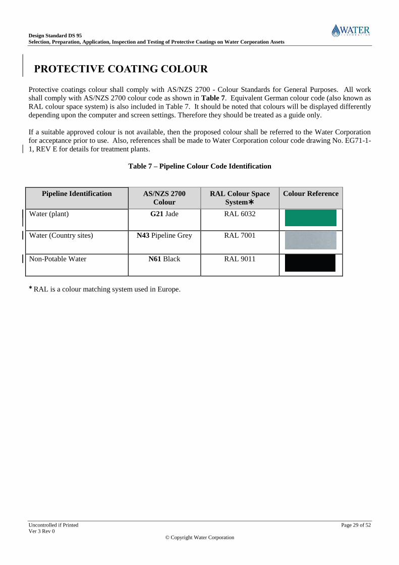
PROTECTIVE COATING COLOUR
Protective coatings colour shall comply with AS/NZS 2700 - Colour Standards for General Purposes. All work
shall comply with AS/NZS 2700 colour code as shown in Table 7. Equivalent German colour code (also known as
RAL colour space system) is also included in Table 7. It should be noted that colours will be displayed differently
depending upon the computer and screen settings. Therefore they should be treated as a guide only.
If a suitable approved colour is not available, then the proposed colour shall be referred to the Water Corporation
for acceptance prior to use. Also, references shall be made to Water Corporation colour code drawing No. EG71-1-
1, REV E for details for treatment plants.
Table 7 – Pipeline Colour Code Identification
Pipeline Identification
AS/NZS 2700
Colour
RAL Colour Space
System
Colour Reference
Water (plant)
G21 Jade
RAL 6032
Water (Country sites) N43 Pipeline Grey RAL 7001
Non-Potable Water N61 Black RAL 9011
RAL is a colour matching system used in Europe.

Design Standard DS 95
Selection, Preparation, Application, Inspection and Testing of Protective Coatings on Water Corporation Assets
Uncontrolled if Printed Page 30 of 52 Ver 3 Rev 0
© Copyright Water Corporation
WATER CORPORATION COATING SPECIFICATIONS
10.1 DS 95 Compliance Design Standard DS 95 is aligned with AS/NZS 2312 for both Atmospheric and Non-Atmospheric type coatings.
Atmospheric environments are classified into corrosivity categories (Very Low - A to Inland Tropical - F) based on
the corrosion rates of mild steel given in International Standard Organisation (ISO) 9223. Non-atmospheric
environments fall into the category of potable water immersion, sewerage immersion, soil etc.
The alignment of DS 95 to AS/NZS 2312 will assist corrosion engineers, design consultants and coating inspectors
to understand and select the correct specification for the various Water Corporation applications. To further assist
asset designers and maintenance planners a library of surface preparation and coating specifications have been
developed for typical Water Corporation applications and are included in Appendix 2 and 3. It is the intention of
the Asset Durability team to expand on this list of specifications based on future requirements.
10.1.1 Choosing the Right Specification In order to choose the right specification for various Water Corporation assets, atmospheric and non-atmospheric
conditions are sub-divided into immersed or non-immersed micro environments. In simple terms, coating systems
consisting of metallic zinc or compounds of zinc are used only for non-immersed environments with or without top
colour coat.
On the other hand, coating systems such as high build epoxies and elastomeric urethanes, where no zinc is present
are applied for immersed environments without top coats. There are exceptions where a coating system can be
used in both the immersed and non-immersed environments e.g. Epoxy Mastic.
Careful consideration shall be given to some coating systems where the specified nominal dry film thickness is
greater than the AS/NZS 2312 or equivalent to the ISO 9223 standard.
Also, when selecting a coating system suitable for the environmental classification, the coating system shall have a
minimum design life to first minor maintenance of 10 years, which is categorised as no more than 1% of the total
surface area having corrosion of the parent metal.
Atmospheric corrosivity categories per the requirements of AS/NZS 2312, may not include coatings which are to
be immersed, buried or in any macro/microenvironment which may differ from atmospheric corrosion conditions
such as the internal of tanks etc.
The atmospheric categories for coating system selection shall be as follows;
• C1 – Very Low. Environments in this category are mostly found inside heated or air-conditioned buildings with
clean atmospheres.
• C2 – Low. Environments in this category include dry rural areas as well as other regions remote from the coast or
sources of pollution.
• C3 – Medium. This category mainly covers coastal areas with low salinity.
• C4 – High. This category occurs mainly on the coast.
• C5 – Very High (Industrial and Marine). This category is common offshore and on the beachfront in regions of
rough seas and surf beaches.
For any coatings subject to buried, immersion or macro/micro environmental conditions, the Team Leader – Asset
Durability shall be contacted for any special requirements regarding protective coating system selection.

Design Standard DS 95
Selection, Preparation, Application, Inspection and Testing of Protective Coatings on Water Corporation Assets
Uncontrolled if Printed Page 31 of 52 Ver 3 Rev 0
© Copyright Water Corporation
10.1.2 Coating Thickness Deviation It is the responsibility of the design consultant to ensure that the specified thickness in the specification will not
impede the tolerances and clearances of various mechanical components. The design consultant should discuss the
coating requirement thickness with the Team Leader – Asset Durability.
The Water Corporation recommends use of the following coating types on potable/wastewater infrastructures.
10.2 Group B - Inorganic Zinc Silicate Inorganic Zinc Silicate also known as IZS consists of finely divided metallic zinc dispersed in a self-curing
inorganic alkyl (ethyl) silicate medium. IZS coatings react with steel to form a chemical bond.
The zinc dust metal provides galvanic corrosion protection to the mild steel substrate. If the IZS coating is
damaged, the zinc silicate film repairs itself and protects steel substrate by sacrificial cathodic protection. IZS
coating are mainly used for non-immersed environments.
Too thick a coating of IZS, will result in “Mud Cracking”.
10.3 Group C - Zinc Rich Epoxy Primer Zinc Rich Epoxy primer is an organic coating and depends on physical rather than chemical bonding to steel. It
contains zinc in powdered metallic form dispersed in organic base (Epoxy) and curing agent (Polyamide).
Zinc rich epoxy is easier than IZS to apply without mud cracking. Top coat is easier to apply and cures at a faster
rate compared to IZS. The advantage of zinc rich epoxy is that it is more surface tolerant compared to IZS. Zinc
Rich Epoxy primers are mainly used for non-immersed environments.
10.4 Group D – High Build Epoxy Epoxies consists of an epoxy base with an amine adduct or polyamide curing agent as the resin binder. The colour
range is limited, usually flat or low gloss. May be used as finish coat but their main disadvantage is they chalk and
discolour with UV radiation but this has little detrimental effect on performance. This can be overcome by
applying a polyurethane or acrylic epoxy topcoat to give a glossy finish for extra protection.
Epoxies are hard, tough coatings with good chemical and solvent resistance. In situations, where more than 1000
microns thickness of coating is required then Ultra High Build Epoxy is preferred. High Build Epoxies are mainly
used for potable water and wastewater immersed environments.
10.5 Group E – Epoxy Mastic Consists of an epoxy resin base with an adduct or polyamide curing agent with evaporative hydrocarbon and
alcohol, or ketone or glycol ether solvent (or combinations of each). Hand or power tool cleaned steel substrate can
be coated with Epoxy Mastic and hence referred to as ‘surface tolerant epoxy’. Epoxy Mastic coatings can be
brushed or rolled.
Epoxy Mastics are mainly used as maintenance coatings and can be used for both immersed and non-immersed
potable water and wastewater environments.

Design Standard DS 95
Selection, Preparation, Application, Inspection and Testing of Protective Coatings on Water Corporation Assets
Uncontrolled if Printed Page 32 of 52 Ver 3 Rev 0
© Copyright Water Corporation
10.6 Group F – Mineral Filler Epoxy Mineral flake coatings contain microns thick mineral flakes which make the coating much tougher than ordinary
industrial paint. Glass flake particles form dense, inert barriers within the paint film. Overlapping layers of glass
resist water and chemicals permeating into the paint film. The addition of glass also increases the flexibility,
hardness and abrasion resistance of coatings.
Glass flake coatings can be used for both immersed and non-immersed potable water and wastewater environments.
10.7 Group G - Fusion Bonded Epoxy Powder FBE powder coating is applied on the surface by pre-heating the substrate. The epoxy resin forms cross-linking
reaction which is irreversible i.e. after the curing, the coating cannot be returned to its original form by any means.
The coating can be used for pipelines buried in soil, immersed and non-immersed environments in both potable
water and wastewater assets.
10. 8 Group H – Galvanising Galvanising is the process of applying a protective zinc coating to steel or iron, to prevent rusting. The zinc coating
protects the substrate by the Galvanic method and is mainly used for non-immersed environments.
10. 9 Group I – Elastomeric Polyurethanes (Polyurea etc.) Polyurea is a type of elastomer that is derived from the reaction product of an isocyanate component and a
synthetic resin blend.
Polyurethane and polyurea elastomeric membranes are exceptionally tough and flexible to compensate for the
movement and cracking of substrates – particularly concrete. They are mainly used for potable water and
wastewater immersed environments.
10. 10 Group J – Anti-graffiti Coating Anti-graffiti coatings try to prevent the permanent adherence of graffiti on painted surfaces, where once the surface
has been tagged maintenance personal can remove the unwanted graffiti without damaging the original protective
coatings. The anti-graffiti coating should be resistant to the solvents typically used for the removal of the graffiti
without permanent damage of the anti-graffiti coating system.
10. 11 Group K – Water Based Acrylic Coating Water based coatings can be applied to damp surfaces and are used for decorative purposes. Also used to maximise
resistance to weathering and hence retain colour well with time. These paints also emit low amounts of Volatile
Organic Compounds (VOCs), which is good for the environment. The disadvantage is if there is excessive
moisture on the material being coated, then the adhesion of the paint is reduced resulting in failure of paint due to
blistering.
10. 12 Group L – Tape Wrapping and Heat Shrink Sleeve Tape wrapping is a form of corrosion protection for pipelines, valves, gear boxes etc. \ It is fast and relatively
simple to apply by hand.
Heat Shrink Sleeves are heat shrinkable polyethylene sleeves which provide extremely tough anti-corrosion
protection for welded pipeline joints and factory coating repairs. They are compatible with all commonly used pipe
coatings and are suitable for operation from -20°C up to 80°C.

Design Standard DS 95
Selection, Preparation, Application, Inspection and Testing of Protective Coatings on Water Corporation Assets
Uncontrolled if Printed Page 33 of 52 Ver 3 Rev 0
© Copyright Water Corporation
10. 13 Group M – Miscellaneous Coating The above type of coating systems are applied to pipework, pipelines and other assets that encounter concrete and
other types of assets.
Figure 12 shows the coating selection matrix for a new potable and wastewater structure. Appendix 2 shows the
Water Corporation coating specifications that are suitable for various potable and wastewater assets.

Design Standard DS 95
Selection, Preparation, Application, Inspection and Testing of Protective Coatings on Water Corporation Assets
Uncontrolled if Printed Page 34 of 52 Ver 3 Rev 0
© Copyright Water Corporation
Figure 12 - Coating selection matrix for a new potable and wastewater structure.
Stainless
Non-Immersed
No
Carbon

Design Standard DS 95
Selection, Preparation, Application, Inspection and Testing of Protective Coatings on Water Corporation Assets
Uncontrolled if Printed Page 35 of 52 Ver 3 Rev 0
© Copyright Water Corporation
11 COATING SYSTEMS FOR NEW WATER CORPORATION ASSETS
Tables 8 and 9 provide appropriate coating systems for the common structures found in Water Corporation, water
and wastewater treatment facilities. The tables also contain the assets common materials of construct and their
typical exposure condition. Some assets may not have been listed or may be known by some other name.
If a substrate is left uncoated or a coating is intended for protection against specific chemicals, ensure that the
material has an adequate corrosion resistance for the specific environment.
Pipes, valves, fittings that have factory-applied fusion bonded external/internal coating or suitable cement lining
typically do not require additional coatings.
Any coating in contact with drinking water shall be certified to comply with AS/NZS 4020 by a NATA accredited
laboratory. Design consultants, asset maintainers and coating contractors shall refer to Schedule 5 – List of
products approved for use in Drinking Water issued by the Department of Health, Western Australia requested
through the Water Corporation.
If there is any doubt in the selection of coatings, then the matter should be referred to the Team Leader – Asset
Durability.
Refer Appendix 3 for commonly used coatings in potable water and wastewater infrastructures. The coating
industry technical terms are included in Appendix 4.

Design Standard DS 95
Selection, Preparation, Application, Inspection and Testing of Protective Coatings on Water Corporation Assets
Uncontrolled if Printed Page 36 of 52 Ver 3 Rev 0
© Copyright Water Corporation
Table 8 – Examples of typical coatings for assets associated with potable water
Item Substrate
Surface Prep.
Specification
Coating
Specification
Micro
Environment
Environment
Classification Comments
1
Hand rails Galvanised Steel
H2 Above Ground
C1 – C3 If colour coat is required refer
item2
2 Hand rails Galvanised Steel A3 E4 Above Ground C4 – C5
3 Hand rails Aluminium
Above Ground N/A No Coating Required
Pipes Carbon Steel A1 B1 Above Ground C1 – C4
Pipes Carbon Steel A1 C2 Above Ground
C1 – C5 If top colour coat is required for
aesthetic purposes
Pipes
Fusion Bonded
Polyethylene
(Sintakote) A7 E5 Above Ground
C1 – C5 If top colour coat is required for
aesthetic purposes on Sintakote
pipe/fittings
Pipes
Fusion Bonded
Polyethylene
(Sintakote)
Below Ground
N/A No Coating Required. Bare steel
sections to be wrap in accordance
with L1 or L2

Design Standard DS 95
Selection, Preparation, Application, Inspection and Testing of Protective Coatings on Water Corporation Assets
Uncontrolled if Printed Page 37 of 52 Ver 3 Rev 0
© Copyright Water Corporation
Table 8 - Examples of typical coatings for assets associated with potable water (continued…)
Item Substrate
Surface Prep.
Specification
Coating
Specification
Micro
Environment
Environment
Classification Comments
Pipework PVC A6 K1 Above Ground
C1 – C5 To protect against UV rays
Building Structural
Steel Carbon steel
H2
Above Ground/
Non-Immersed
C1 – C4 Contact Durability team for
alternative options
Table 9 - Examples of typical coatings for assets associated with Wastewater
Item Substrate
Surface
Prep.
Specification
Coating
Specification
Micro
Environment
Environment
Classification
Comments
Hand rails Galvanised Steel
H2
Above Ground or
Non-Immersed
C1 – C2
No Coating Required
Hand rails Aluminium
Above Ground C1 – C4
No Coating Required
Pipeworks PVC A6 K1 Above Ground
C1 – C5 To protect against UV rays
Steel Tank internal Carbon steel A1 D1 Immersed N/A
Steel Tank external Carbon steel A1 C2
Above Ground/Non-
Immersed
C1 – C5
Concrete Tank Concrete A5 D3
Immersed/Non-
Immersed
C1 – C5 Coating shall extend down to a
level 500 mm below the lowest
service water level in the structure
Concrete Tank Concrete A5 I1
Immersed/Non-
Immersed
C1 - C5

Design Standard DS 95
Selection, Preparation, Application, Inspection and Testing of Protective Coatings on Water Corporation Assets
Uncontrolled if Printed Page 38 of 52 Ver 3 Rev 0
© Copyright Water Corporation
12 PIPELINES COATING – BURIED & EXPOSED (ATMOSPHERIC )
12.1 Buried Pipework
12.1.1 Buried Pipework (Workshop Manufacture) Where MSCL pipes with fusion bonded polyethylene coating (Sintakote
®) are used to fabricate pipe fittings the
coating shall be stripped back a minimum of 75mm away from the actual weld. On completion of welding the
stripped areas in the case of Sintakote pipe or fittings fabricated from rolled plate shall be coated as per the
requirements shown in Table 10.
12.1.2 Coating Requirements (Workshop Manufacture) Prior to application of the protective coating system, surfaces shall be prepared such that rust and any other deleterious material are removed, in accordance with the coating manufacturer’s requirements. In all circumstances, clean and prepare the surface to be protected. The minimum surface preparation requirements
shall be degreasing and mechanical wire brushing to obtain Class 2 cleanliness in accordance with AS/NZS1627
Part 2 for heat shrink sleeve and tape wrapping installation. Heat shrink sleave products as shown in Tables 10 and
11 are suitable for both workshop and field installations. A Class 3 blast finish is required for the application of Epoxy spray applied coatings in accordance with AS/NZS1627 Parts 4 and 9. Fusion bonded medium density polyethylene coatings shall be applied in accordance with AS/NZS 4321 by steel
Mains and or approved applicators only. Contractors seeking to use other applicators shall seek approval from the
Team Leader – Asset Durability before surface treatment is commenced.
Water Corporation approved

Design Standard DS 95 Selection, Preparation, Application, Inspection and Testing of Protective Coatings on Water Corporation Assets
Uncontrolled if Printed Page 39 of 52 Ver 3 Rev 0
© Copyright Water Corporation
Table 10 – External Coating Buried Pipework – Workshop Fabricated fittings
APPLICABLE COATINGS
Option 1 Note 4
Option 2 Note 4
Option 3 Note 4
Option 4 Note 4
FITTING TYPE Sintakote®
Coating
Heat Shrink Sleeve (L2)
Epoxy Coated (Spray Applied)
Tape Wrapping
Straight Section Joints & Segmented Bends (Fabricated from Sintakote Pipe or rolled plate)
Yes Refer Note 3
Yes Canusa-CPS
®, AQW-HS
®
Refer Note 3
NA NA
Flanged Connections (straight section)
NA NA NA Yes (Specification L1 System B)
Refer Note 2 &3
Crotch Plated Tees Yes Refer Note 3
NA Yes Refer Note 3
NA
Valve to Pipe Flanges NA NA NA Yes (Specification L1 System B)
Refer Note 2 &3
Access / Inspection Opening Yes (Note 1 & 3)
NA Yes Refer Notes 1 & 3
Yes (Specification L1 System B)
Refer Note 2 &3 Air Valve Off-take / spigot Yes
(Note 1 & 3) NA Yes
Refer Notes 1 & 3 NA
Scours Off-take / spigot Yes (Note 1 & 3)
NA Yes Refer Notes 1 & 3
NA
Notes: 1. Scours, inspection openings and air valve fittings where ‘Sintakote’ coated or epoxy mastic coated shall be coated to within 75 mm of the rear face of the flange.
2. The Petrolatum 4 step system comprises of the application of a primer, packing with mouldable / profiling mastic, wrapping with grease-impregnated tape and final
wrapping with a self-adhesive PVC overwrap. Profiling Mastic shall be used for flange connections. Petrolatum wrappings shall be applied as per the
manufacturer’s recommendation.
3. Pipe work assemblies that are corrosion protected as per Table 10 above and where the period of storage on site exceeds 6 months shall be adequately protected
against ultraviolet and direct sunlight to prevent the coating systems from deterioration.
4. Options for coatings shall be selected in the order of priority, Option 1 being the most effective and Option 4 the least effective. Option 1 shall be adopted, unless
product is unavailable.

Design Standard DS 95 Selection, Preparation, Application, Inspection and Testing of Protective Coatings on Water Corporation Assets
Uncontrolled if Printed Page 40 of 52 Ver 3 Rev 0
© Copyright Water Corporation
Table 11 – External Coating Buried Pipework – Field Applied
APPLICABLE COATINGS
Option 1 Note 4
Option 2 Note 4
FITTING TYPE Heat Shrink Sleeve (L2)
Note 3
Tape Wrapping (L1)
Note 3
Straight Section Joints & Segmented Bends (Fab. from Sintakote Pipe or rolled plate)
Yes Canusa- CPS
®, AQW-HS
®
Yes Densopol 80
® (Rockrap 4000
®) (As per note 2)
Flanged Connections NA Yes Specification L1 System B) (Note 1)
Valve To Pipe Flanges NA Yes (Specification L1 System B) (Note 1)
Access / Inspection Opening NA Yes (Specification L1 System B) (Note 1)
Air Valve & Off-take / Spigot NA Yes (Specification L1 System B) (Note 1)
Scour Off-take / Spigot NA Yes (Specification L1 System B) (Note 1)
Magflow Meter Flanges (Only) NA Same as for Valve to pipe flange
Field Patch Repairs Yes Canusa CRP
® (Repair Patches)
NA
Notes: 1. The Petrolatum 4 step system comprises of the application of a primer, packing with mouldable / profiling mastic, wrapping with grease-impregnated tape and final
wrapping with a self-adhesive PVC overwrap. Profiling Mastic shall be used for all flange connections. Petrolatum tape wrapping shall be applied as per the
manufacturer’s recommendation.
2. The following coating strip widths shall apply:
- ≤ DN 300 Radius Bends - Strip Width equals 50 mm;
- ≥DN 300 ≤ DN 600 Radius Bends - Strip Width equals 100 mm;
- ≥DN 600 Radius Bends - Strip Width equals 150 mm.
3. Reference to Water Corporation Specifications.
4. Options for coatings shall be selected in the order of priority, Option 1 being the most effective.

Design Standard DS 95 Selection, Preparation, Application, Inspection and Testing of Protective Coatings on Water Corporation Assets
Uncontrolled if Printed Page 41 of 52 Ver 3 Rev 0
© Copyright Water Corporation
Heat shrink sleeves shall only be installed by accredited and trained applicators. Contractors seeking to use other
suppliers of heat shrink sleeves shall seek approval from the Superintendent. Heat shrink sleeves shall be applied
in accordance with Corporation’s Technical Specification L2 Heat Shrink Sleeve Requirements.
Epoxy coatings shall be applied to fittings and large assemblies as shown in Table 10. The coating shall be applied
as per the Corporation’s surface preparation specification “A1” and the paint manufacturer’s recommendation.
The epoxy coating thickness shall be 2000 microns DFT minimum. Epoxy coating shall overlap Sintakote coatings
on pipe sections by 100 mm . Epoxy coatings shall be selected in accordance with Appendix 3 - commoly used
coatings in potable water and wastewater infrastructures unless approved otherwise by the Team Leader –
Asset Durabilityand shall not be susceptible to cathodic dis-bonding.
Coating data sheets shall be provided to the Superintendent for coating acceptance and approval, a minimum of 2
weeks prior to the commencement of work. Coating data sheets shall verify that the proposed epoxy coatings has
been tested in accordance with AS/NZS 4352 – Testing for coating resistance to cathodic dis-bonding.
Coatings shall be spray applied Epoxy coated fittings shall be thoroughly inspected prior to installation on-site to
identify transportation and construction damage to the coating. All site coating repairs shall be undertaken by an
approved applicator and spark tested to the test parameters noted in Table 12.
Tape wrapping shall be carried out as per the Corporation’s specification ‘L1’ as applicable. The wrapping shall
overlap the polyethylene coating (Sintakote) by a minimum of 100 mm.
During fabrication, the internal cement mortar lining shall be stripped back to a minimum of 50 mm away on either
side of the actual weld to prevent damage to the existing lining. On completion of welding the internal cement
lining shall be reinstated in accordance with the Water Corporation’s specification M8.
Temporary lifting lugs shop welded to assist with manufacture and transportation of pipe fittings shall be removed
and dressed back prior to field coating/wrapping.
Fittings that are not covered in Table 10 schedule and cannot be epoxy coated or heat shrink sleeve wrapped shall be Petrolatum tape wrapped as per Option 4. All coatings, wrappings and shrink sleeves shall be spark tested by the Contractor and witnessed by the Superintendent using high voltage brush methods to AS 3894.1 prior to backfilling. Spark testing equipment shall be within 2 years of calibration. Spark testing Voltage parameters shall be as per Table 12.
12.1.3 Buried Pipework (Field Applied) Prior to application of the protective coating system, surfaces shall be prepared such that rust and any other deleterious material are removed in accordance with the coating manufacturer’s requirements. Refer Table 10 for requirements of typical coating applications. In all circumstances, clean and prepare the surface to be protected. The minimum surface preparation requirements shall be degreasing and mechanical wire brushing to obtain a St2 cleanliness in accordance with AS/NZS 1627 Part 2. Coating for straight section -surfaces at field welded butt joints, SSJ, RRJ, RRJ-WR, flat and convex banded connections (Per AY58-19-1) shall be made using the Canusa-CPS
® Aquashield AQW-HS
® product or tape
wrapping as per Table 11. Application of heat shrink sleeves shall be in accordance to the Corporation’s specification M2. Joints in ‘Uneven’ surfaces that will result in voids under the protective coating such as bends, tees, flanges, flange bolts and valve body assembly bolts shall be tape wrapped. The area with abrupt profile changes shall be filled with a mouldable mastic to obtain a smooth even profile.

Design Standard DS 95 Selection, Preparation, Application, Inspection and Testing of Protective Coatings on Water Corporation Assets
Uncontrolled if Printed Page 42 of 52 Ver 3 Rev 0
© Copyright Water Corporation
Where pipe transitions from below ground to above ground exist, tape wrapping shall extend to 100mm above finished ground level. Tape wrapping shall be in accordance to the Corporation’s specification L2. Damaged Sintakote pipe coatings and or heat shrink sleeves shall be repaired using the Canusa CRP
® (Coating
Repair Patches), patch repairs shall be made following the manufacturers recommended practice. Damaged epoxy coating shall be repaired using the same products and procedures as used in the workshop manufacturing process. Additionally, minor nicks and scratches in the factory applied Sintakote coating can be repaired using extrusion welding. Personnel carrying out the repair shall be trained and competent to PMB01 (Plastic Welding) competency and certificated by a nationally accredited training organisation. All wrappings and shrink sleeves shall be spark tested by the Contractor and witnessed by the Superintendent using high voltage brush methods to AS 3894.1 prior to backfilling. Spark testing equipment shall be within 2 years of calibration.
Table 12 – Spark Testing Parameters
Coating Process Test Voltage (Min.) Tolerance Medium Density PE Coating 12 kV Per AS 3894.1
Heat Shrink Sleeves 12 kV Per AS 3894.1 Epoxy Coating ( D4) 8 Kv Per AS 3894.1
Densopol 80 (Wrapping) 12 kV Per AS 3894.1
Petrolatum 4 Step System NA NA
12. 2 Exposed Pipework Where pipes and fittings are to be installed above ground, they shall be coated with a suitable system to suit the environmental classification and surrounding corrodents, refer to Coating specification M1
12. 2.1 IZS Primed Pipes & Where bare steel pipes are to be IZS coated they shall be coated in the workshop in accordance with Water Corporation
Specifications A1 and B1.
where inorganic zinc silicate (IZS) are damaged during transit and installation, they shall be reinstated using Water
Corporation specification H3.
Where a colour top coat is specified on the drawings , coating specification A1 and C2 shall be use instead of IZS.
12. 2.2 Sintakote Coated Pipes & fittings Where Sintakote coated pipe and fittings are specified for above ground application, the Sintakote shall be whip
blasted to remove the gloss surfaces and provide a surface profile in accordance with Water Corporation
Specification A7. The prepared surfaces shall be coated in accordance with Water Corporation specification M2.
For welded joints, the joints shall be coated in accordance with Water Corporation specification M2.
Finish coating colour shall be in accordance with the AS/NZS 2700 and the Corporation’s Drawing EG71-1-1 Rev E.
12. 3 Miscellaneous Pipework Configuration Coating For below ground to above ground pipe transitions the coating application shall be in in accordance with Water
Corporation coating specification M1. The coating procedure for clean skin pipe when permanently exposed to
atmosphere shall be coated in accordance with Water Corporation coating specification M3.
When pipe sections are joined by coupling joints (e.g. Straub®, Gibault
®, Viking Johnson
®, Klamflex
®), then the
coating shall be applied in accordance with Water Corporation coating specification M4.
Coating of steel pipes and the Sintakote®
pipes at the concrete interface shall be carried out in accordance with Water
Corporation specifications M5 and M6 respectively. Decorative coatings on galvanised steel shall be carried out in
accordance with Water Corporation specification M7. For the cement mortar relining, references shall be carried
out in accordance with Water Corporation specification M8.

Design Standard DS 95 Selection, Preparation, Application, Inspection and Testing of Protective Coatings on Water Corporation Assets
Uncontrolled if Printed Page 43 of 52 Ver 3 Rev 0
© Copyright Water Corporation
Finish coating colour shall be in accordance with the AS/NZS 2700 and the Corporation’s Drawing EG71-1-1 Rev E.
13 VALVES COATING
13.1 Coating of Valves The purpose behind coating a valve is to extend its service life. All new valves shall be coated in accordance with the
relevant Water Corporation Strategic Product Specification (SPS).
Refurbished valves shall be coated as follows:
DN 600 and below control valves are coated with High Build Epoxy or Fusion Bonded Epoxy (FBE) in accordance
with Water Corporation coating specifications E2 and G2 respectively.
Above DN600, control valves are coated with two or more coats of a two pack Epoxy .coating system in accordance
with Water Corporation coating specification E2.
All sizes of Non-return valves, coating shall be carried out in accordance with Water Corporation coating specification
E2.
For hard wearing applications (where abrasion, impact and chemical resistance are required), control valves are
coated with high build ceramic filled epoxy coatings in accordance with Water Corporation specification F2.
For Butterfly valves including Seal on Disc and Seal on Body, coating shall be applied by the application of two or
more coats of High Build Epoxy in accordance with Water Corporation coating specification D2.
14 PUMPS COATING
14.1 Coating of Pumps For the wetted areas of new and existing pumps, coating shall be carried out using High Build Ceramic Filled Epoxy in
accordance with Water Corporation coating specification F3.

Design Standard DS 95
Selection, Preparation, Application, Inspection and Testing of Protective Coatings on Water Corporation Assets
Uncontrolled if Printed Page 44 of 52 Ver 3 Rev 0
© Copyright Water Corporation
15 APPENDIX 1 – INSPECTION, TESTS AND PLAN (ITP)
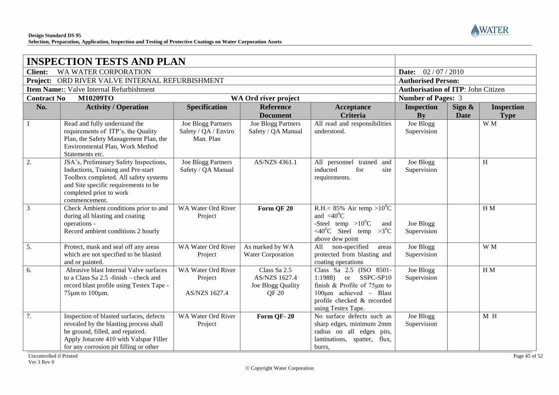
Design Standard DS 95
Selection, Preparation, Application, Inspection and Testing of Protective Coatings on Water Corporation Assets
Uncontrolled if Printed Page 45 of 52 Ver 3 Rev 0
© Copyright Water Corporation
INSPECTION TESTS AND PLAN
Client: WA WATER CORPORATION Date: 02 / 07 / 2010
Project: ORD RIVER VALVE INTERNAL REFURBISHMENT Authorised Person:
Item Name:: Valve Internal Refurbishment Authorisation of ITP: John Citizen
Contract No M10209TO WA Ord river project Number of Pages: 3
No. Activity / Operation
Specification Reference
Document
Acceptance
Criteria
Inspection
By
Sign &
Date
Inspection
Type 1 Read and fully understand the
requirements of ITP’s, the Quality
Plan, the Safety Management Plan, the
Environmental Plan, Work Method
Statements etc.
Joe Blogg Partners
Safety / QA / Enviro
Man. Plan
Joe Blogg Partners
Safety / QA Manual
All read and responsibilities
understood.
Joe Blogg
Supervision
W M
2. JSA’s, Preliminary Safety Inspections,
Inductions, Training and Pre-start
Toolbox completed. All safety systems
and Site specific requirements to be
completed prior to work
commencement.
Joe Blogg Partners
Safety / QA Manual
AS/NZS 4361.1 All personnel trained and
inducted for site
requirements.
Joe Blogg
Supervision
H
3 Check Ambient conditions prior to and
during all blasting and coating
operations -
Record ambient conditions 2 hourly
WA Water Ord River
Project Form QF 20 R.H.< 85% Air temp >10
0C
and <400C
-Steel temp >100C and
<400C Steel temp >3
0C
above dew point
Joe Blogg
Supervision
H M
5. Protect, mask and seal off any areas
which are not specified to be blasted
and or painted.
WA Water Ord River
Project
As marked by WA
Water Corporation
All non-specified areas
protected from blasting and
coating operations
Joe Blogg
Supervision
W M
6. Abrasive blast Internal Valve surfaces
to a Class Sa 2.5 -finish – check and
record blast profile using Testex Tape -
75µm to 100µm.
WA Water Ord River
Project
AS/NZS 1627.4
Class Sa 2.5
AS/NZS 1627.4
Joe Blogg Quality
QF 20
Class Sa 2.5 (ISO 8501-
1:1988) or SSPC-SP10
finish & Profile of 75μm to
100μm achieved – Blast
profile checked & recorded
using Testex Tape.
Joe Blogg
Supervision
H M
7. Inspection of blasted surfaces, defects
revealed by the blasting process shall
be ground, filled, and repaired.
Apply Jotacote 410 with Valspar Filler
for any corrosion pit filling or other
WA Water Ord River
Project Form QF- 20 No surface defects such as
sharp edges, minimum 2mm
radius on all edges pits,
laminations, spatter, flux,
burrs,
Joe Blogg
Supervision
M H

Design Standard DS 95
Selection, Preparation, Application, Inspection and Testing of Protective Coatings on Water Corporation Assets
Uncontrolled if Printed Page 46 of 52 Ver 3 Rev 0
© Copyright Water Corporation
INSPECTION TESTS AND PLAN
Client: WA WATER CORPORATION Date: 02 / 07 / 2010
Project: ORD RIVER VALVE INTERNAL REFURBISHMENT Authorised Person:
Item Name:: Valve Internal Refurbishment Authorisation of ITP: John Citizen
Contract No M10209TO WA Ord river project Number of Pages: 3 imperfections.
8. Mix paint as per manufacturers
recommended procedure –
RECORD BATCH NUMBERS
QF 20
Jotun Technical
Specifications
UHB
Data Sheet
Fully mixed as per
manufactures instructions
Batch numbers on Form
QF.20
Joe Blogg
Supervision
M W
9. Check Ambient conditions prior to and
during all blasting and coating
operations -
Record ambient conditions 2 hourly
Joe Blogg Quality
Manual
AS/NZS 1627.4
Form QF 20 R.H.< 85%-Air tem>100C
and <400Steel temp >10
0C
and <400C
-Steel temp >30C above
Joe Blogg
Supervision
M W
10. Apply a stripe coat of Jotun UHB,MTO
to all edges– monitor WFT regularly
during application and record ambient
conditions every 2 hours on Form
QF.20
JOTSPEC
Wa Water Ord River
Project
Form QF -20
All specified surfaces
coated, no runs, sags, drips
excessively thick coating,
etc. minimum
Joe Blogg
Supervision
HOLD - M
12. Check Ambient conditions prior to and
during all blasting and coating
operations -
Record ambient conditions 2 hourly
Joe Blogg Quality
Manual
AS/NZS 1627.4
Form QF 20 R.H.< 85%-Air tem>100C
and <400Steel temp >10
0C
and <400C
-Steel temp >30C above dew
point
Joe Blogg
Supervision
W M
13. Mix paint as per manufacturers
recommended procedure –
RECORD BATCH NUMBERS
QF 20
Jotun Technical
Specifications Form QF -20
Fully mixed as per
manufactures instructions
Batch numbers on Form
QF.20
Joe Blogg
Supervision
W M
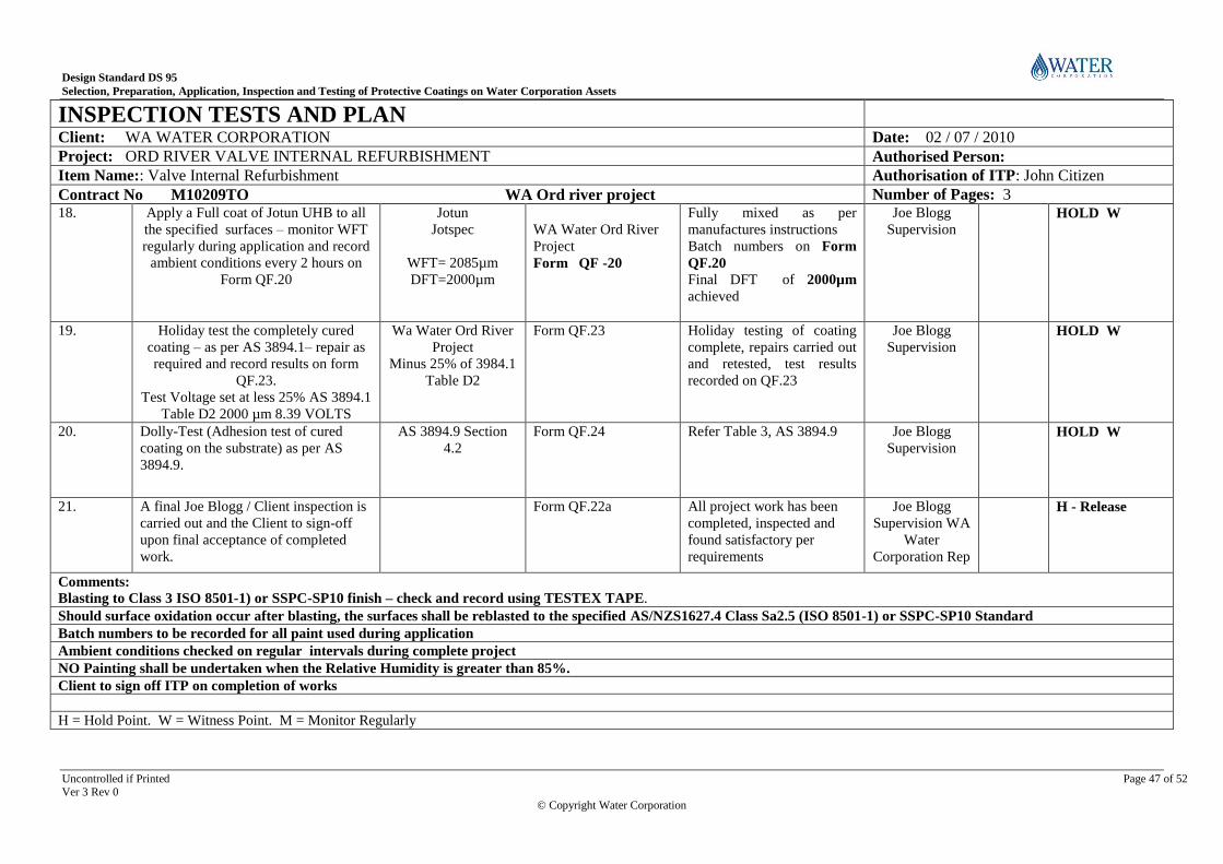
Design Standard DS 95
Selection, Preparation, Application, Inspection and Testing of Protective Coatings on Water Corporation Assets
Uncontrolled if Printed Page 47 of 52 Ver 3 Rev 0
© Copyright Water Corporation
INSPECTION TESTS AND PLAN
Client: WA WATER CORPORATION Date: 02 / 07 / 2010
Project: ORD RIVER VALVE INTERNAL REFURBISHMENT Authorised Person:
Item Name:: Valve Internal Refurbishment Authorisation of ITP: John Citizen
Contract No M10209TO WA Ord river project Number of Pages: 3 18. Apply a Full coat of Jotun UHB to all
the specified surfaces – monitor WFT
regularly during application and record
ambient conditions every 2 hours on
Form QF.20
Jotun
Jotspec
WFT= 2085µm
DFT=2000µm
WA Water Ord River
Project
Form QF -20
Fully mixed as per
manufactures instructions
Batch numbers on Form
QF.20 Final DFT of 2000µm
achieved
Joe Blogg
Supervision
HOLD W
19. Holiday test the completely cured
coating – as per AS 3894.1– repair as
required and record results on form
QF.23.
Test Voltage set at less 25% AS 3894.1
Table D2 2000 µm 8.39 VOLTS
Wa Water Ord River
Project
Minus 25% of 3984.1
Table D2
Form QF.23
Holiday testing of coating
complete, repairs carried out
and retested, test results
recorded on QF.23
Joe Blogg
Supervision
HOLD W
20. Dolly-Test (Adhesion test of cured
coating on the substrate) as per AS
3894.9.
AS 3894.9 Section
4.2
Form QF.24
Refer Table 3, AS 3894.9 Joe Blogg
Supervision
HOLD W
21. A final Joe Blogg / Client inspection is
carried out and the Client to sign-off
upon final acceptance of completed
work.
Form QF.22a All project work has been
completed, inspected and
found satisfactory per
requirements
Joe Blogg
Supervision WA
Water
Corporation Rep
H - Release
Comments: Blasting to Class 3 ISO 8501-1) or SSPC-SP10 finish – check and record using TESTEX TAPE.
Should surface oxidation occur after blasting, the surfaces shall be reblasted to the specified AS/NZS1627.4 Class Sa2.5 (ISO 8501-1) or SSPC-SP10 Standard
Batch numbers to be recorded for all paint used during application
Ambient conditions checked on regular intervals during complete project
NO Painting shall be undertaken when the Relative Humidity is greater than 85%.
Client to sign off ITP on completion of works
H = Hold Point. W = Witness Point. M = Monitor Regularly

Design Standard DS 95
Selection, Preparation, Application, Inspection and Testing of Protective Coatings on Water Corporation Assets
Uncontrolled if Printed Page 48 of 52 Ver 3 Rev 0
© Copyright Water Corporation
16 APPENDIX 2 - SURFACE PREPARATION AND PROTECTIVE COATING SPECIFICATIONS
SYSTEM
DESIGNATION
GROUP – A (SURFACE PREPARATION)
A1 Surface Preparation for the Application of Protective Coating on Steel or Cast Iron
A2 Surface Preparation for the Application of Aesthetic Coating on Stainless Steel
A3 Surface Preparation for the Application of Protective Coating on Galvanised Steel
A4 Surface Preparation for the Application of Protective Coating on Aluminium
A5 Surface Preparation for the Application of Protective Coating on Concrete
A6 Surface Preparation for the Application of Protective Coating on Plastics
A7 Surface Preparation for the Application of Protective Coating on Fusion Bonded Polyethylene (Sintakote®)
SYSTEM
DESIGNATION
COATING SPECIFICATIONS
GROUP – B (INORGANIC ZINC SILICATE)
B1 Inorganic Zinc Silicate Coating on Steel or Cast Iron
GROUP – C (ZINC RICH EPOXY PRIMER)
C1 Zinc Rich Epoxy Primer Coating on Steel or Cast Iron
C2 Zinc Rich Epoxy Primer, Epoxy Mastic Coat, Polyurethane Top Coating on Steel or Cast Iron
C3 Zinc Rich Epoxy Primer, Epoxy Mastic Coat on Steel or Cast Iron
C4 Zinc Rich Epoxy Primer, Polyurethane Top Coat on Steel or Cast Iron
GROUP – D (HIGH BUILD EPOXY)
D1 High Build Epoxy Coating on Steel or Cast Iron
D2 High Build Epoxy Coating on Butterfly Valves
D3 High Build Epoxy Coating on New and Old Concrete
D4 Ultra High Build Epoxy Coating on Steel or Cast Iron

Design Standard DS 95
Selection, Preparation, Application, Inspection and Testing of Protective Coatings on Water Corporation Assets
Uncontrolled if Printed Page 49 of 52 Ver 3 Rev 0
© Copyright Water Corporation
SYSTEM
DESIGNATION
COATING SPECIFICATIONS
GROUP – E (EPOXY MASTIC
E1 Epoxy Mastic Coating on Steel or Cast Iron
E2 Epoxy Mastic Polyurethane Top Coat on Control Valves
E3 Epoxy Mastic, Polyurethane Top Coat on Steel or Cast Iron
E4 Epoxy Mastic, Polyurethane Top Coat on Galvanised Steel
E5 Epoxy Mastic, Polyurethane Top Coat on Fusion Bonded Polyethylene (Sintakote)
GROUP – F (MINERAL FILLER EPOXY)
F1 Glass Flake Epoxy Mastic Coating on Steel or Cast Iron
F2 g High Build Ceramic Filled Epoxy Polyurethane Top Coat Coatings For Repair Of Control Valves
F3 High Build Ceramic Filled Epoxy Coating on Pumps
GROUP – G (THERMAL BONDED POWDER)
G1 Thermostatically Applied Polyester Powder Coating for Aluminium Sheet Metal Cabinets
G2 Thermal Bonded Polymeric Coating On Valves And Fittings for Water Industry Purposes
GROUP – H (GALVANISING)
H1 Repair of Galvanised Coating
H2 Hot-Dip Galvanising of Steel Structures
H3 Repair of Inorganic Zinc Silicate (IZS) Coated Structures
GROUP – I (ELASTOMERIC POLYURETHANE)
I1 Elastomeric Polyurethane Protective Coating on Concrete
SYSTEM
DESIGNATION
COATING SPECIFICATIONS
GROUP – J (ANTI-GRAFFITI)
J1 Anti-Graffiti Coating on New and Old Steel Structures
J2 Anti-Graffiti Coating on New and Old Concrete Structures
GROUP - K (WATER BASED ACRYLIC)

Design Standard DS 95
Selection, Preparation, Application, Inspection and Testing of Protective Coatings on Water Corporation Assets
Uncontrolled if Printed Page 50 of 52 Ver 3 Rev 0
© Copyright Water Corporation
SYSTEM
DESIGNATION
COATING SPECIFICATIONS
K1 Aesthetic Finish Coating on Above Ground Plastic Pipes and Fittings
GROUP L - WRAPPING AND HEAT SHRINK SLEEVE
L1 Tape Wrapping Requirements
L2 Heat Shrink Sleeve Procedure
GROUP - M (MISCELLANEOUS)
M1 Above Ground to Below Ground Pipeline Transitional Area and Concrete Encasement Coating Procedure
M2 Coating Procedures for Above Ground Sintakote® Pipe and Steel Pipe Joints
M3 Coating Procedures for Clean Skin Pipe Permanently Exposed to Atmosphere
M4 Coating Procedure for Coupling Jointed Joints
M5 Coating Procedure for Steel Pipe at the Concrete Interface
M6 Coating Procedure For Steel Pipe at the Concrete Interface & Sintakote® Pipe Joint
M7 Coating Procedure on Galvanised Steel for Decorative Purposes in Low Corrosive Environments
M8 Cement Mortar Lining Requirement
M9 Grouting Convex Band in Pipelines

Design Standard DS 95
Selection, Preparation, Application, Inspection and Testing of Protective Coatings on Water Corporation Assets
Uncontrolled if Printed Page 51 of 52 Ver 3 Rev 0
© Copyright Water Corporation
17 APPENDIX 3 - COMMOLY USED COATINGS IN POTABLE WATER AND WASTEWATER INFRASTRUCTURES
Code Jotun Paints International Paints Dulux Paints Wattyl Paints Sigma Paints Ameron PPG Paints
PRIMER
IZS Resist 5 WF
Resist 8 6AU
Interzinc 86
Interzinc 22
Zincanode 304 Galvit ES600 SigmaZinc 170 (D9) Ameron D9
ZINC RICH EPOXY PRIMER
ZRE Barrier Interzinc 42
Interzinc 52
Zincanode 202
Zincanode 402
Galvit EP 100
Galvit EP 102
SigmaZinc 109 HS
SigmaZinc 102
Amercoat 471
EPOXY PRIMER
EP Penguard Express ZP
Penguard Special
Intergard 345 Durepon P14
Duremax GPE ZP
Epinamel PR 360 SigmaCover 256
SigmaPrime 200
Amercoat 182 ZPK
BARRIER COAT
EM Jotamastic 87/90
Jotacote 605*
Penguard Express (MIO)
Interseal 670HS
Interplus 1180
Interplus 356 (MIO)
Durebild STE
Durebild STE (MIO)
Epinamel DTM985* SigmaCover 640
SigmaCover 435 (MIO)
SigmaCover 640 (MIO)
Amerlock 400
HBE Tankguard 412*
Penguard HB
Interline 975*
Interzone 954
Durebild HSE*
Duremax GPE*
Epinamel TL710*
Epinamel TL770SF*
Sigmaguard CSF 575*
SigmaShield 880
Amercoat CC 703/2
UHB Jotacote UHB Interzone 485 Luxapoxy UHB Dura Plate UHS
GFE Marathon
Jotamastic 87 GF
Interzone 505 Durebild STE GF Epinamel MF920 SigmaShield 880 Amerlock 400GF
EPUR Polybrid 705-E* Flexituff*
TOP COAT
PUR Hardtop AS
Hardtop Flexi
Hardtop XP-Semi Gloss
Interthane 990 Luxathane R Poly U400
Poly U750
SigmaDur 550 Amercoat 450K/
Amershield
AG Imperite 300 Interfine 878 Weathermax HBR
Luxathane R
Acrathane IF
Poly U400 Antigraffiti Clear SigmaDur 550 Clear Amershield Clear
WBA Jotun Interior Primer Intercryl 525 Weathershield Gloss AquaTrim All Weather Gloss PPG Gloss Trade
Acrylic
ZRP Galvanite Interzinc 782 Zincanode 202
Zinc Rich 1P
Galvit EP 100
Galvit EP 102
Sigmazinc 109 HS
Styralux 220
Amercoat 471
CODE
IZS In-Organic Zinc Silicate EM Epoxy Mastic GV Galvanised UHB Ultra High Build Epoxy
ZRE Zinc Rich Epoxy GFE Glass Flake Epoxy EPUR Elastomeric Polyurethane
PUR Polyurethane FBP Fusion Bonded Powder AG Anti-Graffiti
HBE High Build Epoxy TBP Thermal Bonded Polymer WBA Water Based Acrylic
EP Epoxy Primer ZRP Zinc Repair EM (MIO) Epoxy Mastic (Micaceous Iron Oxide)
Notes:
[1] * Complies with AS/NZS 4020 - Testing of products for use in contact with drinking water. Contractor to confirm the validity of AS/NZS 4020 certification with coating supplier before ordering.
[2] Where a coating system requires more than one product to be used (e.g. Primer and top coat) both product shall be from the same supplier unless approved otherwise by the Team Leader Asset Durability
[3] The Water Corporation cannot be held responsible for the claims or performance guarantees offered by coating product suppliers.
[4] Due to continuous product development, coating contractors shall check with product suppliers to confirm that the product names and numbers are current at the time of ordering.

Design Standard DS 95
Selection, Preparation, Application, Inspection and Testing of Protective Coatings on Water Corporation Assets
Uncontrolled if Printed Page 52 of 52 Ver 3 Rev 0
© Copyright Water Corporation
END OF DOCUMENT