Embed Size (px)
Citation preview
DESIGN SPECS FOR SEWAGE DISPOSAL SYSTEMS JUNE 2016.indd 1 2016-07-04 1:30 PM

This document provides a single consolidated design criteria for the following documents referenced in the Sewage Disposal Systems Regulation:
• Septic Systems in the Yukon, Design Specifications for the Septic Tank and Soil Absorption System, Section 21; and• Sewage Holding Tank Standards, Section 22.
No person shall construct, install, enlarge, rebuild, substantially repair, or connect to an existing system, any sewage disposal system or any part thereof, or cause the same to be done, without first obtaining a written permit from a health officer.
9(1) Sewage Disposal Systems Regulation
DESIGN SPECS FOR SEWAGE DISPOSAL SYSTEMS JUNE 2016.indd 2 2016-07-04 1:30 PM
1
Design Specifications for Sewage Disposal Systems
J U N E 2 0 1 6
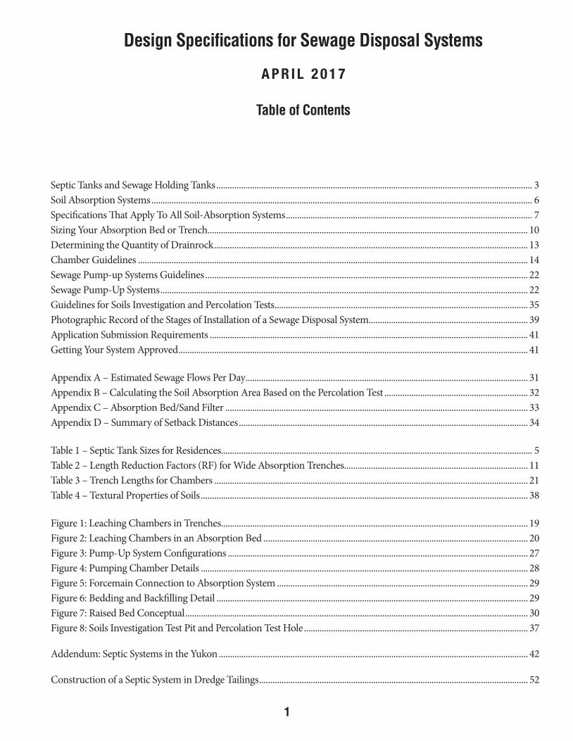
Table of Contents
Septic Tanks and Sewage Holding Tanks ............................................................................................................................................. 3Soil Absorption Systems .......................................................................................................................................................................... 6Specifications That Apply To All Soil-Absorption Systems .............................................................................................................. 7Sizing Your Absorption Bed or Trench............................................................................................................................................... 10Determining the Quantity of Drainrock ............................................................................................................................................ 13Chamber Guidelines .............................................................................................................................................................................. 14Sewage Pump-up Systems Guidelines ................................................................................................................................................ 22Sewage Pump-Up Systems .................................................................................................................................................................... 22Guidelines for Soils Investigation and Percolation Tests ................................................................................................................. 35Photographic Record of the Stages of Installation of a Sewage Disposal System ....................................................................... 39Application Submission Requirements .............................................................................................................................................. 41Getting Your System Approved ............................................................................................................................................................ 41
Appendix A – Estimated Sewage Flows Per Day .............................................................................................................................. 31Appendix B – Calculating the Soil Absorption Area Based on the Percolation Test ................................................................ 32Appendix C – Absorption Bed/Sand Filter ....................................................................................................................................... 33Appendix D – Summary of Setback Distances ................................................................................................................................. 34
Table 1 – Septic Tank Sizes for Residences........................................................................................................................................... 5Table 2 – Length Reduction Factors (RF) for Wide Absorption Trenches .................................................................................. 11Table 3 – Trench Lengths for Chambers ............................................................................................................................................ 21Table 4 – Textural Properties of Soils .................................................................................................................................................. 38
Figure 1: Leaching Chambers in Trenches......................................................................................................................................... 19Figure 2: Leaching Chambers in an Absorption Bed ...................................................................................................................... 20Figure 3: Pump-Up System Configurations ...................................................................................................................................... 27Figure 4: Pumping Chamber Details .................................................................................................................................................. 28Figure 5: Forcemain Connection to Absorption System ................................................................................................................ 29Figure 6: Bedding and Backfilling Detail ........................................................................................................................................... 29Figure 7: Raised Bed Conceptual ......................................................................................................................................................... 30Figure 8: Soils Investigation Test Pit and Percolation Test Hole .................................................................................................... 37
Addendum: Septic Systems in the Yukon .......................................................................................................................................... 42
Construction of a Septic System in Dredge Tailings ........................................................................................................................ 52
DESIGN SPECS FOR SEWAGE DISPOSAL SYSTEMS JUNE 2016.indd 1 2016-07-04 1:30 PM
A P R I L 2 0 1 7
2Hosp_Doc_SewageDisposalSystems_85238d_Page1.indd 1 2017-03-23 2:57 PM
2
DESIGN SPECS FOR SEWAGE DISPOSAL SYSTEMS JUNE 2016.indd 2 2016-07-04 1:30 PM

3
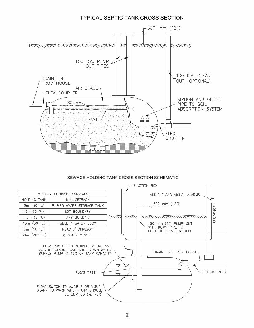
Septic Tanks and Sewage Holding Tanks
1. WASTEWATER – Septic tanks and sewage holding tanks shall receive all wastewater (black and grey water), from toilets, baths, showers, wash basins, sinks and washing machines. Water that must be excluded, includes run-off water from roofs, yards, foundation drains, and other sources not considered to be wastewater (industrial processes).
2. CONSTRUCTION – The construction of septic tanks and sewage holding tanks shall be in accordance with the most current version of CAN/CSA-B66 Design, material, and manufacturing requirements for prefabricated septic tanks and sewage holding tanks. Verification that this requirement has been met shall be provided. Verification may be in the form of:
• Photograph of the CSA certification stamp on the tank • Copy of the CSA certification document specific to that tank • Report from an Engineer that verifies the above construction • Report from an Engineer that the certification is equivalent to CAN/CSA-B66 • Be advised that if tank is to be covered in spray foam, this information must be retrieved accordingly.
NOTE: It is not permissible to modify or convert a septic tank from its original design type to another design type (i.e., trickle tank to siphon tank or vice versa, or a septic tank to a sewage holding tank or vice versa). Only a manufacturer may engage in this activity.
3. TANK BEDDING AND BURIAL – Septic tanks and sewage holding tanks should be buried to provide at least 1.2 m (4 ft) of earth cover. Where this depth requirement is not met, septic tanks and sewage holding tanks shall be insulated with a minimum of 50 mm (2 in) of sprayed on polyurethane insulation and shall have a minimum of 0.6 m (2 ft) of soil cover. All tanks shall be installed as per specific warranty-related standards. (depth limitations, bedding materials, anchoring, etc.) Failure to meet manufacturer’s specifications for installation may void warranty and may preclude the Health Officer’s ability to grant permission to use the system. Also, see # 7 “wet hole” installations.
4. SET-BACK DISTANCES (Appendix D, page 34) – Septic tanks and sewage holding tanks shall not be less than:
• 1.5 m (5 ft) from a parcel boundary or from any building; • 5.0 m (16 ft) from the edge of any road or driveway; • 15.0 m (50 ft) from any source of potable water, or natural boundary or high water level of any surface water
body; • 9.0 m (30 ft) from a buried water storage tank; and • 60.0 m (200 ft) from any community well.
5. LOCATION – Septic tanks and sewage holding tanks shall be located so as to be readily accessible for the pumping out (eduction) of liquid sewage and sludge.
6. BUILDING CONNECTION – A flexible coupling shall be used on the inlet pipe to septic tanks and sewage holding tanks and shall be installed near the entrance to the tank. For septic tanks, a flexible coupling shall also be used on the outlet pipe.
DESIGN SPECS FOR SEWAGE DISPOSAL SYSTEMS JUNE 2016.indd 3 2016-07-04 1:30 PM

4
• Location – Sewage holding tanks should be outside the building and strategically located so as to minimize heat loss, prevent structural damage, and protect the building from contamination. Sewage holding tanks may be located inside a building when required by local climatic conditions (e.g., long periods of below 0°C outside temperatures; permafrost). Pre-authorization is required to install tank within a building. See required set back distances in Appendix D.
• Pump-Out Access – Where, under limited circumstances and with pre-authorization from a Health Officer to do so, a building is serviced by an indoor sewage holding tank and water holding tank, the sewage pump-out line should be on a different wall face than the water fill line. Where they are on the same wall face, there shall be a separation distance between the two connectors of at least 3 m (10 ft), with the sewage connector being located at least 300 mm (1 ft) lower in elevation than the water connector. Both the pump-out line and water fill line should be clearly labelled so that they can be distinguished from one another.
• High Level Alarm & Automatic Water Shut-Off – Sewage holding tanks shall have a functional audible and visual alarm that warns when the tank should be emptied (e.g., 75 per cent full), and both a warning light and an automatic shut-off which activates when the tank is 90 per cent full and turns off the water system to the building so as to prevent the tank from overflowing or backing-up into the building. The floats required to perform these tasks must be mounted on a float tree.
• Drop Pipe – The clean-out pipe(s) should be installed in a manner that avoids risk of damage to floats during
eduction (see image on page 2)
• Minimum Volume – The minimum volume for any sewage holding tank is recommended as 4,500 litres (1,000 imperial gallons).
• For final approval of sewage holding tank, the Health Officer must receive the Septic Tank/Sewage Holding Tank Installation Declaration, the Notification of Installation and Undertaking to Maintain a Sewage Holding Tank along with photographs of installation (please refer to photographic record of stages of installation of the SDS, pg. 39), and written proof from a qualified electrical contractor or a certified electrician that all relevant electrical components have been installed as specified and function accordingly on the Electrical Assurance for Sewage Holding Tanks.
NOTE: Bends in the sewage pipe (the pipe between building and tank) should be avoided at all costs due to risk
of clogging and freezing. Any proposed bends must be based on demonstrated need and are to be documented on application and on associated diagram. Such proposal must be recognized and approved by a Health Officer. Reason for bends in pipes must be clearly stated on application with clear rational (be advised that should bends be necessary the slope must be at least three per cent, bends must be long sweep type 90 degree or two 45 degree with one foot of straight pipe between the bends).
7. “WET HOLE” INSTALLATIONS – Where the septic tank or sewage holding tank may be subject to buoyancy effects caused by high water table or seasonal flooding, the tank shall be anchored in accordance with manufacturer’s requirements. Where no such requirements exist, the installation shall be done in a manner that will not damage the tank or invalidate its warranty
8. SEWAGE HOLDING TANKS ONLY – The installation of a sewage holding tank may be permitted when onsite conditions prevent the installation of a conventional sewage disposal system, consisting of a septic tank and soil absorption system. Sewage holding tanks may also be installed in other situations where a Health Officer is consulted and the proposal evaluated prior to the permit being issued.
DESIGN SPECS FOR SEWAGE DISPOSAL SYSTEMS JUNE 2016.indd 4 2016-07-04 1:30 PM

5
TABLE 1Septic Tank Sizes for Residences
# of
Bedrooms
Minimum Liquid Capacity (not including siphon chamber)
Litres Imp. Gallons2 or less 2747 (600)
3 3409 (750)4 4091 (900)5 4773 (1050)6 5455 (1200)
* Actual size may vary depending on the make and model of the septic tank.
9. SEPTIC TANKS ONLY – There are several types and styles of septic tanks in regards to their ability to discharge sewage. Namely trickle tanks, siphon tanks and pumping chamber units (pump-up systems). Only siphon style septic tanks are to be used unless it is demonstrated to the Health Officer that a siphon system is not possible. In such a case the Health Officer may consider an alternate design.
• Septic Tank Volumes – The volume of septic tanks is dependent on the size and type of the building(s) to which it will be connected:
• Residential (Less Than 6 Bedrooms) – The volumes of septic tanks required for residences are outlined in Table 1 (below):
DESIGN SPECS FOR SEWAGE DISPOSAL SYSTEMS JUNE 2016.indd 5 2016-07-04 1:30 PM
6
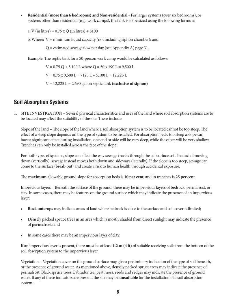
• Residential (more than 6 bedrooms) and Non-residential - For larger systems (over six bedrooms), or systems other than residential (e.g., work camps), the tank is to be sized using the following formula:
a. V (in litres) = 0.75 x Q (in litres) + 5100
b. Where: V = minimum liquid capacity (not including siphon chamber); and
Q = estimated sewage flow per day (see Appendix A) page 31.
Example: The septic tank for a 50-person work camp would be calculated as follows:
V = 0.75 Q + 5,100 L where Q = 50 x 190 L = 9,500 L
V = 0.75 x 9,500 L = 7125 L + 5,100 L = 12,225 L
V = 12,225 L = 2,690 gallon septic tank (exclusive of siphon)
Soil Absorption Systems
1. SITE INVESTIGATION – Several physical characteristics and uses of the land where soil absorption systems are to be located may affect the suitability of the site. These include:
Slope of the land – The slope of the land where a soil absorption system is to be located cannot be too steep. The effect of a steep slope depends on the type of system to be installed. For absorption beds, too steep a slope can have a significant effect during installation, one end or side will be very deep, while the other will be very shallow. Trenches can only be installed across the face of the slope.
For both types of systems, slope can affect the way sewage travels through the subsurface soil. Instead of moving down (vertically), sewage instead moves both down and sideways (laterally). If the slope is too steep, sewage can come to the surface (break-out) and create a risk to human health through accidental exposure.
The maximum allowable ground slope for absorption beds is 10 per cent; and in trenches is 25 per cent.
Impervious layers – Beneath the surface of the ground, there may be impervious layers of bedrock, permafrost, or clay. In some cases, there may be features on the ground surface which may indicate the presence of an impervious layer:
• Rock outcrops may indicate areas of land where bedrock is close to the surface and soil cover is limited;
• Densely packed spruce trees in an area which is mostly shaded from direct sunlight may indicate the presence of permafrost; and
• In some cases there may be an impervious layer of clay.
If an impervious layer is present, there must be at least 1.2 m (4 ft) of suitable receiving soils from the bottom of the soil absorption system to the impervious layer.
Vegetation – Vegetation cover on the ground surface may give a preliminary indication of the type of soil beneath, or the presence of ground water. As mentioned above, densely packed spruce trees may indicate the presence of permafrost. Black spruce trees, Labrador tea, peat moss, reeds and sedges may indicate the presence of ground water. If any of these indicators are present, the site may be unsuitable for the installation of a soil absorption system.
DESIGN SPECS FOR SEWAGE DISPOSAL SYSTEMS JUNE 2016.indd 6 2016-07-04 1:30 PM
7
Vehicular traffic – Soil absorption systems should be situated where there will never be any possibility of future vehicular traffic. Driveways, parking or storage areas, snowmobile or bike trails should never pass over any part of a sewage disposal system. Undisturbed snow cover reduces heat loss and helps to prevent sewage disposal systems from freezing during winter. Vehicular traffic can also cause vibration within the soil, or cause soils to settle unevenly.
2. SET-BACK DISTANCES – (See Appendix D, page 34). A soil absorption system shall not be less than: • 30.0 m (100 ft) from any source of potable water (e.g., drinking water well); • 30.0 m (100 ft) from any the natural boundary or high water level of any surface water body (e.g., pond, lake,
stream, river); • 9.0 m (30 ft) from a buried drinking water holding tank; • 60.0 m (200 ft) from any community well; and • 1.2 m (4 ft) from the seasonal high ground water level.
3. TYPES OF SOIL ABSORPTION SYSTEMS – There are three types of soil absorption systems which are generally used. The absorption bed, the absorption trench (wide or deep) and chamber systems. All have different characteristics and applications, see below for more detail.
Pumps can also be used to lift sewage from a lower elevation where the septic tank is located, to a higher elevation where the soil absorption system is located. Pump-up systems are discussed on page 22.
Once a potentially suitable site for the future soil absorption system has been chosen, a soils investigation and percolation test must be performed in accordance with the criteria laid out in the Guidelines for Soils Investigation and Percolation Tests section on page 35.
PLEASE NOTE: site specific characteristics may require or allow for the minimum requirements detailed in this document to be varied. The overriding consideration for varying a requirement is the protection of human health and the application of sound environmental health principles. The decision for varying a minimum requirement rests with an Environmental Health Officer.
Specifications That Apply To All Soil Absorption Systems
Refer to diagrams in the addendum: Septic Systems in the Yukon, on page 42.1. A soil absorption system shall be located not less than 5 m (16 ft) from a parcel boundary and any road or
driveway; 6 m (20 ft) from any building; 9 m (30 ft) from a buried water storage tank; 30 m (100 ft) from any source of potable water, or natural boundary or high water level of any water body; and 60 m (200 ft) from any community well.
2. Minimum soil cover over system is 1.2 m (4 ft) without insulation. With a minimum of 50 mm (2 in) of approved rigid insulation, soil cover may be reduced to a minimum of 0.6 m (2 ft).
3. There must be a minimum of 1.2 m (4 ft) of vertical separation between the bottom of a bed and the seasonally high groundwater table and/or impervious layer such as bedrock, fractured or weathered bedrock, clay or permafrost.
4. Drainrock must be clean with no more than 3 per cent fines (0.080 mm screen) residual after screening, and be between 20 to 65 mm (3/4 to 2-1/2 in) in size. Drainrock is to cover the entire absorption area, and surround the perforated pipes with a minimum of 2 inches placed over the pipe. To calculate the amount of drainrock required, refer to “DETERMINING THE QUANTITY OF DRAINROCK” on page 13.
5. Perforated pipe must be installed level or to a maximum slope of 0.3 per cent with perforation holes at 4 and 8 o’clock. One additional 13 mm (½ in) hole should be drilled through the bottom section of each pipe length to allow for complete drainage of the pipes.
DESIGN SPECS FOR SEWAGE DISPOSAL SYSTEMS JUNE 2016.indd 7 2016-07-04 1:30 PM

8
5. Perforated pipe must be installed level or to a maximum slope of 0.3 per cent with perforation holes at 4 and 8 o’clock. One additional 13 mm (½ in) hole should be drilled through the bottom section of each pipe length to allow for complete drainage of the pipes.
6. All piping and fittings must meet appropriate CSA standards (e.g., 4-inch PVC solid and perforated pipes).7. Maximum length of perforated pipe runs is 20 m (66 ft). This is a maximum length and it is recommended that
for a more uniform and equal distribution of effluent a length of 12 m (40 ft) be used.8. Base Preparation: In receiving soils with a percolation rate slower than 10 min./25 mm, the base should be
scarified with a rake to help prevent smearing of the soil surface, and a 75 mm (3 in) thick layer of clean sand (less than 3 per cent fines) may be placed on the base prior to placing the pipe. The main purpose of the sand is to allow the biomat to develop in the sand layer rather than in the tighter soils at the infiltrative surface, which will enhance the system efficiency.
9. The sewage disposal system shall be so designed and constructed as to promote even distribution of effluent throughout the soil absorption area. An uneven number of perforated pipe runs requires a “double header” type connection.
10. Monitoring standpipes should be installed and are to extend to the bottom of the bed, and be detached from the rest of the system. This pipe is to be a minimum of 100 mm (4 in) in diameter with holes drilled in part of pipe embedded in the drainrock, extend above the ground surface, and be capped.
11. Cleanout standpipes are to be a minimum of 100 mm (4 in) in diameter, extend above the surface, and be capped. These pipes extend vertically up from the closed-system of lateral pipes used in transporting the sewage effluent throughout the field.
12. A silt barrier (geotextile or ridged insulation) must be installed between the top of the drainrock and the native soil backfill in order to keep the drainrock free of fines.
13. Bottom of the excavation must be level throughout.14. The finished grade over the bed must be mounded to prevent the formation of a depression after settling, and allow
for the run off of surface water. The area around the system should be graded to divert all surface runoff.
Absorption Beds Only1. Maximum allowable slope of bed is recommended two per cent but should be level.2. The maximum slope of the ground in the area that the bed is to be installed shall be no greater (steeper) than 10 per
cent. 3. Drainrock depth below pipe must be a minimum 150 mm (6 in) and must extend throughout the entire base of
required excavation dimensions.4. Drainrock is to surround and extend 50 mm (2 in) above perforated pipe.5. Distance between runs of perforated pipes is 1.8 m (6 ft). The edge distance between the outside pipe and the edge
of the bed must be one-half the pipe spacing or 0.9 m (3 ft).6. At least one monitoring stand pipe should be installed and located near the centre of the bed.7. Two cleanout standpipes are to be located diagonally on the absorption bed system (on opposite and far corners of
one another), which also will aid in determining the location of the bed.8. Only the bottom area of a bed may be considered in determining the total absorption area.9. The bottom of a bed should be scarified or raked before placement of drainrock.10. A two-foot sand filter is required where the percolation rate is faster than five minutes. 11. Only absorption bed style of systems may be installed in fast percolating soils.12. Systems with an odd number of perforated pipe runs are to have a “double header” to ensure even distribution of
effluent.
DESIGN SPECS FOR SEWAGE DISPOSAL SYSTEMS JUNE 2016.indd 8 2016-07-04 1:30 PM

9
Wide Trench Only
See Specifications 1 to 14 listed in this booklet on pages 7-8 as they also apply to aspects of trench installations.
1. Maximum allowable ground slope in area of a trench is 25 per cent.
2. Absorption trench must be installed parallel to the slope contour.
3. Trench width must be 0.9 to 1.5 m (3, 4, or 5 ft) wide (Table 2, page 11) unless otherwise approved by a Health Officer.
4. When two or more trenches are being used, the horizontal distance between the trench walls must be three times the depth of drainrock below the perforated pipe or 3 m (10 ft), whichever is greater.
5. The depth of drainrock below the perforated pipe must be not less than 0.3 m (1 ft) or greater than 1.2 m (4 ft).
6. A monitoring standpipe should be installed near the end of each trench. It is to be separate from the rest of the distribution pipes.
7. A cleanout standpipe is to be installed at the end of each run of perforated pipe.
8. The bottom and sides of a wide trench must be scarified or raked before placement of drainrock.
9. The side wall and bottom area of the trench will be used in determining the absorption area. A reduction factor (see Table 2, page 11) to the total area will apply.
Deep Trench Only
See Specifications 1 to 14 listed in this booklet on pages 7-8 as they will apply to aspects of trench installations.
1. Maximum allowable ground slope in area of trench is 25 per cent.
2. Trench must be installed parallel to the slope contour.
3. Depth of drainrock below pipe must be a minimum 1.0 m (3.3 ft).
4. A monitoring standpipe should be installed near the end of each lateral trench, unattached from the rest of the system.
5. A cleanout standpipe is to be installed at the end of each run of perforated pipe.
6. The sides of the trench walls must be scarified or raked before placement of drainrock.
7. The absorbing soil strata must be a least 1.2 m (4 ft) thick.
8. Only the sidewall area of a deep trench may be considered in determining the total absorption area. The bottom of the trench shall also be within acceptable percolation rates.
9. The maximum allowable depth of a deep trench is 4 m (13 ft).
10. When two or more trenches are being used, the horizontal distance between the trench walls must be three times the depth of drainrock below the perforated pipe or 3.7 m (12 ft), whichever is greater.
DESIGN SPECS FOR SEWAGE DISPOSAL SYSTEMS JUNE 2016.indd 9 2016-07-04 1:30 PM
10
Sizing your Absorption Bed or Trench
After the average percolation rate (GUIDELINES for SOILS INVESTIGATION and PERCOLATION TESTS, page 35) has been calculated and the type of soil absorption system has been determined, the minimum surface area required for your sewage disposal system can be obtained by using Appendix B, page 32. This area is based on the number of bedrooms in a standard household, assuming a water usage of 570 litres per bedroom (125 Imperial gallons per bedroom). Pages 14-21 cover Chamber Systems.
If you have used Appendix A to determine the estimated volume of sewage flow in a 24-hour period, divide by 570 L (125 imp. gal.) to obtain the bedroom equivalence.
TOTAL AREA REQUIRED = AREA FOR ONE BEDROOM x # OF BEDROOMS (from Appendix B)
Absorption Bed
Example 1
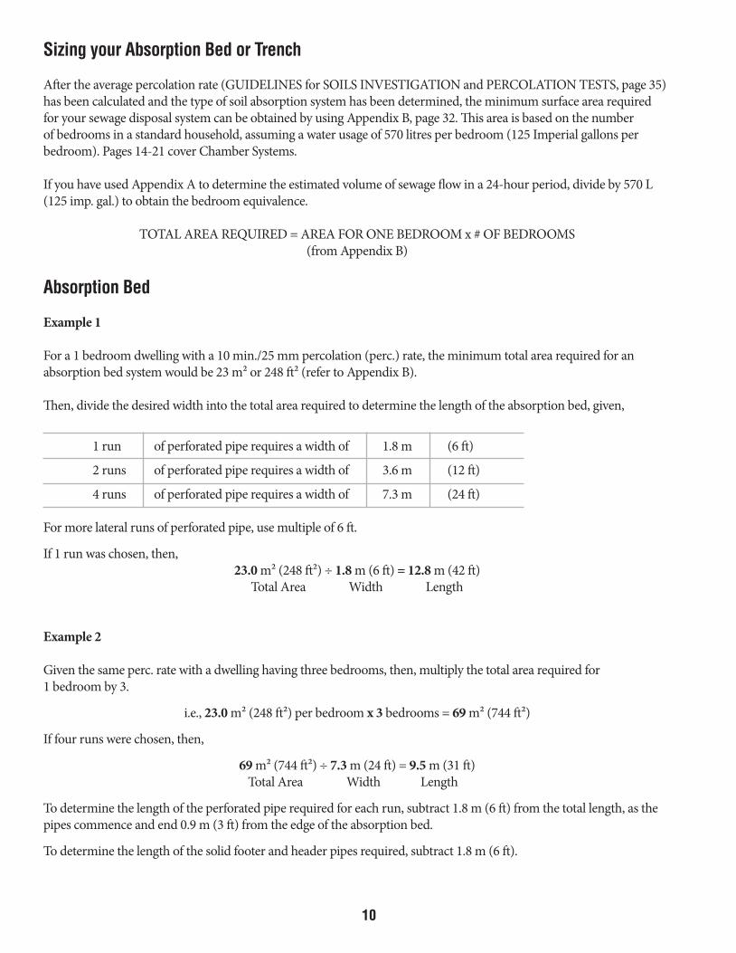
For a 1 bedroom dwelling with a 10 min./25 mm percolation (perc.) rate, the minimum total area required for an absorption bed system would be 23 m² or 248 ft² (refer to Appendix B).
Then, divide the desired width into the total area required to determine the length of the absorption bed, given,
1 run of perforated pipe requires a width of 1.8 m (6 ft)
2 runs of perforated pipe requires a width of 3.6 m (12 ft)
4 runs of perforated pipe requires a width of 7.3 m (24 ft)
For more lateral runs of perforated pipe, use multiple of 6 ft.
If 1 run was chosen, then, 23.0 m² (248 ft²) ÷ 1.8 m (6 ft) = 12.8 m (42 ft)
Total Area Width Length
Example 2
Given the same perc. rate with a dwelling having three bedrooms, then, multiply the total area required for1 bedroom by 3.
i.e., 23.0 m² (248 ft²) per bedroom x 3 bedrooms = 69 m² (744 ft²)
If four runs were chosen, then,
69 m² (744 ft²) ÷ 7.3 m (24 ft) = 9.5 m (31 ft) Total Area Width Length
To determine the length of the perforated pipe required for each run, subtract 1.8 m (6 ft) from the total length, as the pipes commence and end 0.9 m (3 ft) from the edge of the absorption bed.
To determine the length of the solid footer and header pipes required, subtract 1.8 m (6 ft).
DESIGN SPECS FOR SEWAGE DISPOSAL SYSTEMS JUNE 2016.indd 10 2016-07-04 1:30 PM
11
Wide Trench
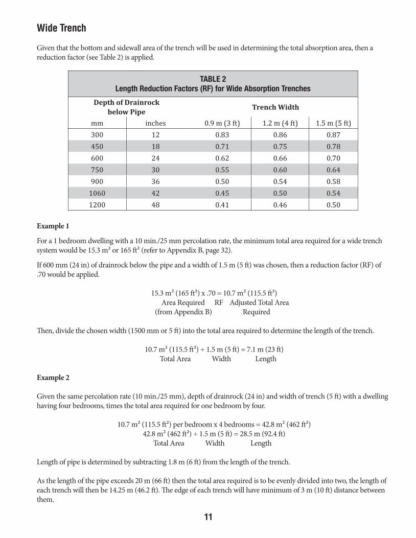
Given that the bottom and sidewall area of the trench will be used in determining the total absorption area, then a reduction factor (see Table 2) is applied.
Example 1
For a 1 bedroom dwelling with a 10 min./25 mm percolation rate, the minimum total area required for a wide trench system would be 15.3 m² or 165 ft² (refer to Appendix B, page 32).
If 600 mm (24 in) of drainrock below the pipe and a width of 1.5 m (5 ft) was chosen, then a reduction factor (RF) of .70 would be applied.
15.3 m² (165 ft²) x .70 = 10.7 m² (115.5 ft²) Area Required RF Adjusted Total Area (from Appendix B) Required
Then, divide the chosen width (1500 mm or 5 ft) into the total area required to determine the length of the trench.
10.7 m² (115.5 ft²) ÷ 1.5 m (5 ft) = 7.1 m (23 ft) Total Area Width Length
Example 2
Given the same percolation rate (10 min./25 mm), depth of drainrock (24 in) and width of trench (5 ft) with a dwelling having four bedrooms, times the total area required for one bedroom by four.
10.7 m² (115.5 ft²) per bedroom x 4 bedrooms = 42.8 m² (462 ft²)42.8 m² (462 ft²) ÷ 1.5 m (5 ft) = 28.5 m (92.4 ft)
Total Area Width Length
Length of pipe is determined by subtracting 1.8 m (6 ft) from the length of the trench.
As the length of the pipe exceeds 20 m (66 ft) then the total area required is to be evenly divided into two, the length of each trench will then be 14.25 m (46.2 ft). The edge of each trench will have minimum of 3 m (10 ft) distance between them.
TABLE 2Length Reduction Factors (RF) for Wide Absorption Trenches
Depth of Drainrockbelow Pipe
Trench Width
mm inches 0.9 m (3 ft) 1.2 m (4 ft) 1.5 m (5 ft)300 12 0.83 0.86 0.87450 18 0.71 0.75 0.78600 24 0.62 0.66 0.70750 30 0.55 0.60 0.64900 36 0.50 0.54 0.58
1060 42 0.45 0.50 0.541200 48 0.41 0.46 0.50
DESIGN SPECS FOR SEWAGE DISPOSAL SYSTEMS JUNE 2016.indd 11 2016-07-04 1:30 PM
12
Deep Trench
Since only the side walls of the soil absorption area are taken into consideration the following formula applies:
Total Area Required x No. of Bedrooms(from Appendix B)
= Length of Trench2 x Depth of Drainrock Below Pipe
Example 1
For a one-bedroom dwelling with a 10 min./25 mm percolation rate, the minimum total absorption area required for a deep trench system would be 15.3 m² or 165 ft² (refer to Appendix B, page 32).
If 1.2 m (4 ft) of drain rock was placed below the pipe, then,
15.3 m² (165 ft²) x 1 bedroom = 6.3 m (20.6 ft)
2 x 4 ft
Example 2
Given the same percolation rate, and depth of drainrock with a dwelling having four bedrooms, then, times the total area required for one bedroom by four.
15.3 m² (165 ft²) x 4 bedrooms = 25.5 m (82.5 ft)
2 x 4 ft
Length of pipe is determined by subtracting 1.8 m (6 ft) from the length of the trench.
As the length of the pipe exceeds 20 m (66 ft) then the total area required is to be evenly divided into two. The length of each trench will then be 12.75 m (42 ft). The edge of each trench will have minimum of 3.7 m (12 ft) distance between them.
DESIGN SPECS FOR SEWAGE DISPOSAL SYSTEMS JUNE 2016.indd 12 2016-07-04 1:30 PM

13
Determining the Quantity of Drainrock
To determine the amount of drainrock needed for a soil absorption system, the following formula (imperial measure only) may be used:
length (ft) x width (ft) x depth (ft) of area to be filled with drainrock = amount in cubic yards 27 One truck load is approximately 12 cubic yards.
Example 1
The size of the absorption bed is 7.3 m (24 ft) x 14 m (46 ft) and depth of drainrock required (including pipe cover) is 0.3 m (1 ft), then the calculation would be:
24 ft x 46 ft x 1 ft 40.8 cubic yards = 27 Approximately 3½ truck loads
Example 2
The length of each 1.5 m (5 ft) wide trench is 14 m (46 ft) and depth of drainrock required (including pipe cover) is 0.76 m (2.5 ft), then the calculation would be:
46 ft x 5 ft x 2.5 ft 42.5 cubic yards x 2 trenches = 27 Approximately 3½ truck loads
DESIGN SPECS FOR SEWAGE DISPOSAL SYSTEMS JUNE 2016.indd 13 2016-07-04 1:30 PM

14
Chamber Guidelines
General:
1. All chambers shall be certified by the International Association of Plumbing and Mechanical Officials (IAPMO) under PS-63-2005 or the most recent versions of the standard. Chambers that may be subjected to vehicle loads shall meet or exceed the requirements of the American Association of State Highway and Transportation Officials (AASHTO) H-20 rating, as defined in PS-63-2005. The AASHTO H-10 rating, as defined in PS-63-2005, is adequate for systems that will not be subject to vehicles or other similar heavy loadings.
2. Manufacturer’s Instructions: Chamber systems shall be installed in accordance with the manufacturer’s instructions, except that in the event of a conflict with these guidelines, the requirements of the guidelines shall apply.
3. Side Openings: Each chamber unit shall have a louvered sidewall open area not less than 35 per cent of the bottom infiltrative area. The sidewall openings shall be designed to restrict the entry of soils into the chamber area. The louvered area shall have a height of at least 150 mm (6 inches).
4. Absorption Bed: The effective infiltrative area provided by the chambers in an absorption bed shall be calculated considering the interior area at the base of the chamber where the sewage effluent contacts the soil. See Appendix B, page 32 - absorption bed column as the total absorption area will be the same as with existing design specifications.
5. Absorption Trench: The effective infiltrative area provided by the chambers in an absorption trench shall be calculated considering the interior area at the base of the chamber and a portion of the trench side walls to the height of the chamber louvers. See Table 3, page 21 for trench calculations.
6. Sand Filter: A 600 mm (24 in) thick sand filter is required beneath chambers where the soil has a percolation rate faster than 5 min./25 mm. In such cases, only absorption beds will be permitted. Absorption trenches are not permitted in fast-perc. soils because the trench sidewalls will not have the required sand filter protection.
7. Depth of Cover: The chambers must be rated for the depth of soil cover over the units. Failure to adhere to manufacturer’s burial limits may void warranty and preclude ability to receive Health Officer approval.
8. Chamber Dimensions: Chambers shall be a minimum of 600 mm (24 in) wide and a maximum of 900 mm (36 in) wide.
9. Spacing of Chambers: In absorption beds, chambers shall be spaced no greater than 150 mm (6 in) apart (i.e., from the outside edge to outside edge) and may be placed edge-to-edge. In trenches, adjacent trenches shall be a minimum of 2 m (6 ft) from sidewall to sidewall.
10. Base Preparation: In receiving soils with a percolation rate slower than 10 min./25 mm, the base should be scarified with a rake to help prevent smearing of the soil surface, and a 75-mm (3 in) thick layer of clean sand (less than 3 per cent fines) may be placed on the base prior to placing the chambers. The main purpose of the sand is to allow the biomat to develop in the sand layer rather than in the tighter soils at the infiltrative surface, which will enhance the system efficiency. The sand can also be used as a levelling course to ensure that the chambers are laid onto a level surface and as such the long term performance of the system may be enhanced.
DESIGN SPECS FOR SEWAGE DISPOSAL SYSTEMS JUNE 2016.indd 14 2016-07-04 1:30 PM

15
11. Installation Notes: Care must be taken not to “impact” load the chambers when backfilling. This can occur from machinery dumping fill from high elevations. Backfill should be “ladled” and placed on the chambers and then spread by hand to fill in the voids between each row of chambers in a field, or between the chambers and earth walls in a trench. Consult the manufacturer’s product installation instructions regarding the operation of machinery over the chamber.
12. Perforated Piping within Chambers: Although not mandatory, perforated piping may be installed within the chambers to enhance the distribution of effluent along the trench or within a field. When installed, the piping should be supported above the ground surface at least 25 mm (1 in) using PWF lumber or other suitable materials, at intervals that will not result in the pipe sagging when distributing effluent. The extra 12 mm (½ in) dia. hole in the bottom of the perforated piping should only be installed in the last length of pipe in a run, to allow more effluent to continue to the end of the pipe run and allow for better distribution within the drain-field. The perforated piping should be laid a maximum slope of 0.5 per cent to allow for distribution of effluent to the end of each run.
13. Inspection Port: An inspection port or monitoring standpipe shall be installed at the end of each trench and in each corner of an absorption bed. It shall consist of a 100 mm (4 in) dia. PVC pipe connected to the top of the chamber and extending to 300 mm (12 in) above ground, and capped. This allows for monitoring of system performance.
14. Prevention of Soil Erosion: In order to dissipate the hydraulic energy of the effluent discharging into the end of the chamber and to minimize soil erosion, protection shall be provided, which may consist of:
• The product-specific splash plate that is compatible with the chamber end cap system and is capable of extending to a point below the influent entry point.
• GEOTEXTILE covering the base area of the chamber and extending at least 1.5 m (4 ft) from the beginning of the chamber, or
• A 50 MM (2 IN) THICK LAYER OF GRAVEL extending at least 1.5 m (4 ft) from the beginning of the chamber,
or • OTHER SUITABLE MEANS to dissipate the hydraulic energy and prevent erosion to the satisfaction of the
Health Officer.
15. Length of Chamber Run: The maximum allowable length of chamber run is 20 m (66 ft). This is a maximum length and it is recommended that for a more uniform and equal distribution of effluent a length of 12 m (40 ft) be used.
16. Depth of Cover: The minimum allowable depth of earth cover over the top of the chambers without styrofoam board insulation is 1.2 m (4 ft). Soil cover may be reduced to a minimum of 0.6 m (2ft) when the system is covered with 50 mm (2 in) of approved rigid styrofoam type insulation.
17. Pump-Up Systems: Pump-up systems with gravity discharge will normally provide for improved distribution of effluent within the chambers. The Sewage Pump-Up Systems Guidelines shall be followed, pages 22-30.
18. Pressure Distribution: In a pressure distribution system, effluent is pumped under pressure to laterals within the chambers where it is evenly distributed to the soil from small diameter orifices in the lateral piping. A properly designed pressure system will provide equal distribution of effluent throughout the chamber system during each pump cycle. With this type of system, the laterals shall be suspended and fastened near the top of the chambers with the effluent being discharged upward to the top of the chamber, allowing it to deflect and be evenly distributed to the soils at the base of the chamber. All pressure distribution systems must be designed by an engineer registered in the Yukon Territory, with the engineer’s seal affixed to the design plans and report.
DESIGN SPECS FOR SEWAGE DISPOSAL SYSTEMS JUNE 2016.indd 15 2016-07-04 1:30 PM
16
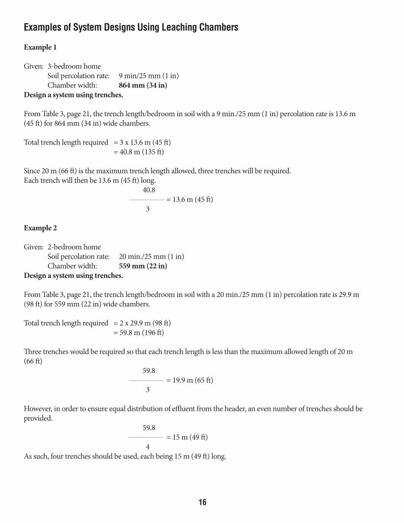
Examples of System Designs Using Leaching Chambers
Example 1
Given: 3-bedroom home Soil percolation rate: 9 min/25 mm (1 in) Chamber width: 864 mm (34 in)Design a system using trenches.
From Table 3, page 21, the trench length/bedroom in soil with a 9 min./25 mm (1 in) percolation rate is 13.6 m (45 ft) for 864 mm (34 in) wide chambers.
Total trench length required = 3 x 13.6 m (45 ft) = 40.8 m (135 ft)
Since 20 m (66 ft) is the maximum trench length allowed, three trenches will be required.Each trench will then be 13.6 m (45 ft) long. 40.8 = 13.6 m (45 ft) 3
Example 2
Given: 2-bedroom home Soil percolation rate: 20 min./25 mm (1 in) Chamber width: 559 mm (22 in)Design a system using trenches.
From Table 3, page 21, the trench length/bedroom in soil with a 20 min./25 mm (1 in) percolation rate is 29.9 m (98 ft) for 559 mm (22 in) wide chambers.
Total trench length required = 2 x 29.9 m (98 ft) = 59.8 m (196 ft)
Three trenches would be required so that each trench length is less than the maximum allowed length of 20 m (66 ft) 59.8 = 19.9 m (65 ft) 3
However, in order to ensure equal distribution of effluent from the header, an even number of trenches should be provided. 59.8 = 15 m (49 ft) 4As such, four trenches should be used, each being 15 m (49 ft) long.
DESIGN SPECS FOR SEWAGE DISPOSAL SYSTEMS JUNE 2016.indd 16 2016-07-04 1:30 PM

17
Example 3
Given: 3-bedroom home Soil percolation rate: 25 min./25 mm (1 in) Chamber width: 864 mm (34 in)Design a system using chambers in an absorption bed.
From Appendix B, page 32, the absorption bed area required per bedroom in soil with a 25 min./25 mm (1 in) percolation rate is 32.4 m² (348 ft²).
Therefore the total area required = 32.4 (348) x 3 = 97.2 m² (1,044 ft²)
With the chambers spaced 152 mm (6 in) apart, the centre-to-centre spacing in the absorption bed will be 1,016 mm = 1.016 m (3.33 ft).
As such, the total length of chambers in the bed will be 97.2 (1,044) = 95.7 m (314 ft) 1.016 (3.33 ft)
This will be divided into runs, each having a maximum length of 20 m (66 ft).
The minimum number of runs require = 95.7 m = approximately 5 runs 20.0 m
However, an even number of runs provides better distribution from the header and as such, six runs should be used. This results in a bed length of:
97.2 m² = 15.9 m (52 ft) = chamber run length 6 x 1.016 m
As such, the absorption bed would be 15.9 m (52 ft) long x 6.1 (6 x 1.016) m (20 ft) wide and will contain six runs of chambers spaced 152 mm (6 in) apart.
An alternative design, which would shorten the chamber run length and improve performance, would be to increase the number of runs to eight.
97.2 m² = 12 m (39 ft) = chamber run length 8 x 1.016 m
In this case, the absorption bed size would be 12 m (39 ft) long x 8.1 m (27 ft) wide and contain eight runs of chambers spaced 152 mm (6 in) apart.
DESIGN SPECS FOR SEWAGE DISPOSAL SYSTEMS JUNE 2016.indd 17 2016-07-04 1:30 PM

18
Example 4
Given: 3-bedroom home Soil percolation rate: 15 min./25 mm (1 in) Chamber width: 559 mm (22 in)Design a system using chambers in an absorption bed.
From Appendix B, page 32, the absorption bed area required per bedroom in soil with a 15 min./25 mm (1 in) percolation rate is 26.4 m² (285 ft²).
Therefore the total area required = 26.4 (285) x 3 = 79.2 m² (855 ft²)
With the chambers spaced 152 mm (6 in) apart, the centre-to-centre spacing in the absorption bed will be 711 mm = 0.71 m (2.33 ft).
As such, the total length of chambers in the bed will be
79.2 (855) = 111.5 m (367 ft) 0.71 (2.33)
This will be divided into runs, each having a maximum length of 20 m (66 ft).
The minimum number of runs require = 111.5 m = approximately 6 runs 20.0 m
This results in a bed length of 79.2 m² = 18.6 m (61 ft) = chamber run length 6 x 0.71 m
As such, the absorption bed would be 18.6 m (61 ft) long x 4.26 (6 x 0.71) m (14 ft) wide and will contain six runs of chambers spaced 152 mm (6 in) apart.
An alternative design, which would shorten the chamber run length and improve performance, would be to increase the number of runs to eight.
Chamber run length = 79.2 m² = 14 m (46 ft) 8 x 0.71 m
In this case, the absorption bed size would be 14 m (46 ft) long x 5.7 m (19 ft) wide and contain eight runs of chambers spaced 152 mm (6 in) apart.
DESIGN SPECS FOR SEWAGE DISPOSAL SYSTEMS JUNE 2016.indd 18 2016-07-04 1:30 PM

19
Figure 1:
DESIGN SPECS FOR SEWAGE DISPOSAL SYSTEMS JUNE 2016.indd 19 2016-07-04 1:30 PM
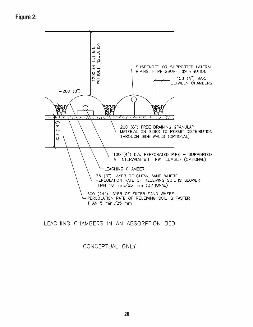
20
Figure 2:
6
DESIGN SPECS FOR SEWAGE DISPOSAL SYSTEMS JUNE 2016.indd 20 2016-07-04 1:30 PM
21
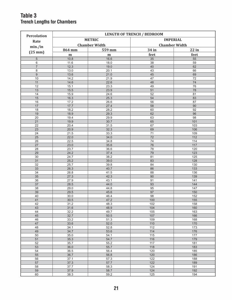
Table 3Trench Lengths for ChambersTABLE 3Trench Lengths for Chambers
PercolationRate
min./in(25 mm)
LENGTH OF TRENCH / BEDROOMMETRIC
Chamber WidthIMPERIAL
Chamber Width864 mm 559 mm 34 in 22 in
m m feet feet55536.618.01595830.816.11626040.913.21766341.020.31896540.126.31927749.122.410147846.226.411167943.321.512187159.325.513118256.429.514138453.523.615178656.622.716109854.727.717129062.822.818169263.929.819189369.924.9102101567.039.9112301765.134.0222601963.239.0232901173.335.1242211270.430.2252411478.435.2262711676.530.3272021876.637.3282321974.732.4292521182.837.4203821380.932.5213031488.937.5223331687.043.6233631885.148.6243931093.243.7253141191.349.7263441390.445.8273741598.440.9283051796.545.9293251894.640.03045510012.745.03148512013.842.13240614019.846.13343615017.942.23446617015.057.23548619013.152.33640710110.256.33743712118.251.43846714116.357.43947715111.450.53059716117.453.53151817112.557.53253818117.550.63355810214.655.63456810218.657.63558812213.751.73659812217.753.73751914213.857.73852914217.859.73954915212.953.8306
DESIGN SPECS FOR SEWAGE DISPOSAL SYSTEMS JUNE 2016.indd 21 2016-07-04 1:30 PM

22
Sewage Pump-up Systems Guidelines
General
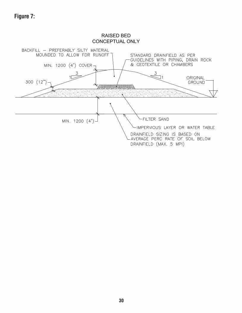
Following are general guidelines for the design and installation of sewage pump-up systems. The types of systems include those that are intended to pump septic tank effluent through a forcemain and into an absorption system for ground treatment and disposal. A sewage pump-up system would typically be required when the effluent must be pumped to a soil stratum at a higher elevation which is more suitable for absorption. (see Figure 7, page 30).
It may also be required where, due to building lot characteristics, house location and topography, the sewage must be pumped to a higher elevation for on-site disposal.
The guidelines are primarily focused on residential applications, but may also be applied to institutional or commercial systems such as for schools, lodges, camps, etc. They are intended to be used as a general guide for contractors and designers and will be used to assist Environmental Health Services when assessing applications received for such systems. They are intended to help ensure that public health and safety issues are adequately addressed and to provide general consistency in the design of key system components.
Sewage Pump-Up Systems
There are three main components to a sewage pump-up system, namely:
• Pump Chamber (receives and holds septic tank effluent)• Pump and Controls (pumps liquid from the tank within liquid level ranges as required)• Forcemain (conveys the effluent under pressure to the soil absorption system where it flows by gravity into the
perforated piping system for treatment and disposal)
Two typical arrangements are depicted in Figure 3 (page 27). These two configurations show the pumping chamber as a compartment within the tank or as a separate stand alone chamber. There are also situations where a lift system precedes the septic tank and is situated in the home basement. In such a case, the pump must be suited to handle raw sewage. Basement-type systems are not specifically reviewed in this document. However, the design principles are similar. The main components of a typical sewage pump-up system are individually discussed as follows.
Pump Chamber
The pump chamber can be a compartment of a septic tank or a self-contained separate tank as shown in Figures 3 and 4 (pages 27-28). Consideration should be given to the use of three compartments, the last of which will house the pump so as to improve the quality of effluent entering the soil absorption system. The following design features shall be adhered to:
• The tank must be structurally sound, watertight and of a material that is non-corrosive or subject to decay. Acceptable materials are fiberglass, polyethylene and concrete and must comply with the most current version of CSA B66.
• The tank must be of sufficient size to store the required volume of sewage for each pump cycle, plus a 15 per cent daily flow reserve capacity above the alarm level in order to prevent sewage backup in the event of pump failure. The reserve capacity should allow for collection of all drainage wastes from the building which is stored (i.e., toilet flush tanks) and under pressure within the system. This assumes that, when the alarm level is reached, the water service pump within the building is automatically shut down.
DESIGN SPECS FOR SEWAGE DISPOSAL SYSTEMS JUNE 2016.indd 22 2016-07-04 1:30 PM
23
• A man-way must be provided in order that the pump and controls can be readily accessed and serviced at any time. The man-way should be at least 600 mm (24 in) in diameter and extend 300 mm (12 in) minimum above grade. (see Figure 4, page 28).
• A frost lid or other suitable method should be provided to prevent loss of heat from the pump chamber during winter. The access man-way can also be insulated with spray-on polyurethane. (see Figure 4, page 28).
• The access lid must be watertight and secured to prevent unauthorized entry.
• After installation, the lift system should be tested for proper operation and the owner provided with an operations and maintenance manual for the system. The O&M manual should include all product specifications for all materials and equipment, plus instructions on operation and maintenance of the system.
Pump and Controls
Pump Selection
There are many types of pumps on the market that are suitable for handling sewage. The most common type used in on-site sewage systems is a submersible centrifugal pump, designed to handle either raw domestic waste or septic tank effluent. The pump must comply with CSA and UL Standards and have a noncorrosive impeller. The pump should be selected based on the following parameters:
• Design pumping rate
• Total Dynamic Head (TDH)
The pumping rate should be sufficient to move the liquid through the forcemain without resulting in any settling of solids within the pipe. The recommended minimum allowable pipe velocity is 0.6 m/s (2 ft/sec). If a 38 mm (1.5 in) forcemain is used, then a flow rate of about 0.8 lps (13 US gpm) would be required to maintain the required 0.6 m/s.
A 0.9 m/s (3 ft/sec.) velocity would require a flow rate of 1.2 lps (19.5 US gpm).
The total dynamic head (TDH) is the sum of the static and friction head that the pump must overcome. The static head is the vertical distance between the low liquid level (shut-off level) in the pump chamber and the pipe discharge level at the absorption bed. The friction head is directly related to the type of pipe used, its diameter, the length of forcemain, and the number and type of fittings used in the line. Published tables can be referenced to determine the head loss for fittings (bends and valves, etc.). However, since these losses are relatively small for this type of system, it is generally acceptable to add 25 per cent to the total pipe length for fitting losses for calculation purposes. A pipe friction loss table is then used to determine the equivalent head loss for various flow rates.
A system head curve is generated by plotting the total dynamic head for various flow rates. This system head curve is applied to a pump performance curve. The pump will perform at any point on the pump performance curve. The intersection of the system head curve with the pump curve is the exact place where this pump will perform under the design conditions in terms of flow rate and total dynamic head. As such, by taking a few simple measurements and making a few calculations, it is possible to select the pump that will best meet the requirements of the system.
DESIGN SPECS FOR SEWAGE DISPOSAL SYSTEMS JUNE 2016.indd 23 2016-07-04 1:30 PM

24
Pump Controls
Level control switches are used for pump start, stop and for the high-level alarm.
• The shut-off level should be set above the pump so that it is kept cool at all times while pumping.
• The pump start level should be set based on the desired volume of effluent to be pumped to the absorption system for each pump cycle. Typically, this volume should be 75 per cent of the volume of the perforated piping in the absorption system or a minimum of 340 litres (75 Igal). This is to provide sufficient volume of liquid during each cycle to inundate all of the perforated pipe system and therefore allow for even distribution of effluent into the receiving soil. As an example, with a 1.5 lps pumping rate and a pump-out volume of 340 litres, the pump will operate for about 3.8 minutes during each cycle. It is desirable to maintain pump cycles to 3-5 per day.
• The high-level alarm should be set at about 75 mm (3 in) above the start level.
• Ensure that the float switches are not restricted from free movement in any way.
Other guidelines pertaining to the pump and controls are as follows:
• Float switches must have a dedicated power supply and be mounted on a separate bracket of float tree so that they can be easily replaced and/or adjusted without removing the pump.
• The high-level switch must activate the alarm and also a weatherproof warning light at the pump up station and an audible alarm.
• The high level switch must also automatically shut off the power to the water supply pump in the building.
• A light should be provided which is activated during the time the sewage pump is running. This can be mounted on the control box and should be easily visible.
• The high-level alarm must be wired separately from the pump and able to be heard within a 30-m radius. The alarm should be placed in a conspicuous location.
• Provide a quick-release coupling on the discharge piping so the pump can be readily removed for servicing. A pump removal assembly must be designed to remove the pump efficiently and safely without having to enter the chamber. Use corrosive resistant fittings.
• It may be advantageous to install a valve on the discharge line so that the discharge flow rate can be adjusted if necessary by throttling.
• The pump must be capable of allowing for drain-back of the forcemain into the pump station after each cycle.
• The pump must be raised from the bottom of the station by at least 200 mm (8 in) to allow for sludge settlement. Concrete blocks or a plastic box may be used for this purpose.
• The electrical controls, relay switches, etc., must be housed within an approved weatherproof enclosure and comply with the Canadian Electrical Code for wet and corrosive locations. It should be positioned outside the pump chamber and allow for easy access for maintenance and adjustment requirements.
• Junction box to be NEMA 4X or equivalent. • The control box is to be built and certified by an authorized manufacturer.
• The power supply entry through the tank must be gas-tight and watertight.
• All wiring must be carried out by a certified electrician who shall provide written confirmation that work has been completed in accordance with the Electrical Code of Canada on the Electrical Assurance for Sewage Pump-up Systems.
Figure 4 (page 28), is a conceptual plan of a typical sewage pump-up station.
DESIGN SPECS FOR SEWAGE DISPOSAL SYSTEMS JUNE 2016.indd 24 2016-07-04 1:30 PM

25
Forcemain
• The recommended material for the forcemain is high-density polyethylene (HDPE). • The class of pipe chosen must be compatible with the anticipated pressures to be encountered with a
minimum class of DR 17. • The pipe diameter should allow for pipe velocities of at least 0.6 m/s (2 ft/sec). For a typical threebedroom
household, the desired pump discharge rate would be in the 1.5 lps (24 USgpm) rate. Using a 38 mm (1.5 in) I.D. pipe, the velocity will be about 1.1 m/s (3.8 ft/sec), which is acceptable. • The forcemain shall be insulated to help guard against freezing if 4-ft burial is not met. • The forcemain should be properly bedded and backfilled. A recommended trenching, bedding and
backfilling detail is shown in Figure 6 (page 29). • The forcemain must be sloped to completely drain the pipe from the discharge point back to the pump
chamber after each pumping cycle. The recommended minimum pipe slope is 2 per cent. • The forcemain connection to the header pipe must be made secured with clamp. Both the forcemain and
header should be bedded in gravel or sand (See Figure 5, page 29). • The forcemain should enter the header pipe from above and must be provided with a vacuum breaker to
prevent back-siphoning should the drain field ever become full.
Operation and Maintenance
• Monitoring, inspection and maintenance should be performed by a qualified person.
• The access manhole and pump chamber must be entered only by persons properly trained in confined space entry and following the requirements as laid out in the General Safety Regulations on Confined Spaces as per the Yukon Occupational Health and Safety Act.
• Periodic checks should be made of the pumping system to ensure that the pump is operating satisfactorily, that the cycling length and frequency are as intended, and that it is functioning as intended.
• Inspect all electrical connections. The level controls should be checked from time to time and the high-level switch should be triggered to ensure that the alarm and light are functioning and that the water pump shut-off is working.
• Inspect all plumbing fittings and connections.
• Routine pump maintenance should be carried out as recommended by the pump manufacturer.
DESIGN SPECS FOR SEWAGE DISPOSAL SYSTEMS JUNE 2016.indd 25 2016-07-04 1:30 PM

26
Raised Bed/Pump Up System Details (Refer to Figure 7)
The natural on-site soils will be considered the receiving soils for which the system sizing must be designed. Percolation test(s) must be performed in this soil strata for the design considerations. See details on percolation test guidelines and Figure 7, and textural properties of soil (Table 4). Ensure that the percolation test is performed and soils are described at the appropriate receiving soils depth (depths will vary according to location of impervious or limiting layer). Keep in mind the required elevation distance between the bottom of the absorption system to the impervious/limiting layer of 1.2m (4 ft).
Filter sand (see Appendix C) must be placed throughout the entire area below the pipes or chambers. See above for sizing of system. (As above, it is not the filter sand that the percolation test rate is calculated at, it is the natural receiving soil below the sand.
To protect against effluent “break-out” there must be adequate receiving soils all around the system to ensure proper treatment. Refer to Figure 7 where there are details of the 3:1 slope requirement whereby for every foot above grade (natural ground level) that the receiving system (pipes or chambers) lays there must be three feet of horizontal material cover from the outside edges of the treatment boundary (this will be the outer edge of outside chambers or to outer edges of the drain rock as it lies above the pipes).
Further to this is the insulation requirement of 1.2 m (4 ft) of soil depth cover above the system to protect against freezing.
Backfill material should be tight silty soil that will allow for water run-off. Owner/installer is obligated to protect the system accordingly.
Please ensure clear legible submission of detailed sketch of this proposal for EHS consideration.
Alternate Sewage System Designs may be approved by a Health Officer. These systems may require plans which have an engineer’s seal before approval will be considered.
Further information on the design and sizing of your sewage system is available from:
Environmental Health Services#2 Hospital RoadWhitehorse, Yukon Y1A 3H8Phone: (867) 667-8391Toll-free (within Yukon) 1-800-661-0408, ext. 8391Fax: (867) 667-8322E-mail: [email protected]
DESIGN SPECS FOR SEWAGE DISPOSAL SYSTEMS JUNE 2016.indd 26 2016-07-04 1:30 PM

27
Figure 3:
DESIGN SPECS FOR SEWAGE DISPOSAL SYSTEMS JUNE 2016.indd 27 2016-07-04 1:30 PM

28
Figure 4:
DESIGN SPECS FOR SEWAGE DISPOSAL SYSTEMS JUNE 2016.indd 28 2016-07-04 1:30 PM

29
Figure 5:
Figure 6:
DESIGN SPECS FOR SEWAGE DISPOSAL SYSTEMS JUNE 2016.indd 29 2016-07-04 1:30 PM
30
Figure 7:
DESIGN SPECS FOR SEWAGE DISPOSAL SYSTEMS JUNE 2016.indd 30 2016-07-04 1:30 PM

31
Appendix A:estimated* sewage flows per day
Establishment Litres Imperial Gallons
APPENDIX AESTIMATED* SEWAGE FLOWS PER DAY
Establishment Litres Imperial Gallons CHURCHES 22 5 per sanctuary seatCAMPS Campground (central comfort station) 130 29 per camper (�lush toilets-no showers) 90 20 per camper Construction Camps (semi-permanent) 190 42 per person Day Camps 55 12 per personCOTTAGES and SMALL DWELLINGS (seasonal occupancy) 160 35 per personDWELLINGS Boarding houses 160 35 per person Apartments (multi-family) 200 44 per person Rooming houses 150 33 per person Single family 570 125 per bedroomFACTORIES No showers 110 24 per employee With showers 150 33 per employeeFOOD SERVICE OPERATIONS: Ordinary restaurant 150 33 per seat 24 hour restaurant 225 49 per seat Tavern 90 20 per seat Curb service 220 48 per car spaceHOTELS (private bath) 200 44 per double roomLAUNDRIES (coin operated) 1700 374 per machineMOTELS 180 40 per double unitNURSING and REST HOMES 450 99 per personOFFICE BUILDINGS 90 20 per employeePICNIC PARKS (bathhouse) 40 9 per picnickerRECREATIONAL VEHICLES PARKS 200 44 per R.V. space (additional information available from Environmental Health Services)SCHOOLS Elementary 45 10 per pupil Jr./Sr. High 70 15 per pupilSWIMMING POOLS 31 7 per swimmer
*The above estimated sewage �lows per day should be used as a guide and represent average �igures for various types of establishments. Actual values may vary, depending on site-speci�ic conditions and usage factors.
DESIGN SPECS FOR SEWAGE DISPOSAL SYSTEMS JUNE 2016.indd 31 2016-07-04 1:30 PM

32
Appendix BCalculating the Soil Absorption Area Based on the Percolation Test
PERCOLATION RATE [minutes per 25 mm (1 in)]
If the percolation test rate is between 0.1 and 5 minutes, the soil is considered too coarse and therefore the percolation rate too fast for trench systems. The absorption bed system must be installed with a sand filter 0.6 m (2ft) below the drain rock.
APPENDIX BCALCULATING THE SOIL ABSORPTION AREA BASED ON THE PERCOLATION TEST
PERCOLATION RATE [minutes per 25 mm (1 in)]
If the percolation test rate is between 0.1 and 5 minutes, the soil is considered too coarse and therefore the percolation rate too fast for trench systems. The absorption bed system must be installed with a sand �ilter 0.6 m (2ft) below the drain rock.
Percolation Rateminutes/25 mm
(1 in)
MINIMUM SOIL ABSORPTION AREA REQUIREDAbsorption Bed Wide & Deep Trench
m²/bedroom ft²/bedroom m²/bedroom ft²/bedroom5216.118814.7155315.213028.8163413.315120.0271510.417220.1288517.417321.2295613.518420.32010718.515527.32115713.613625.42210817.610721.52315812.718728.52410916.715824.62510026.816925.72616021.912031.82712127.918035.82810224.024131.92915229.020237.92021325.126233.03127320.220336.03223426.226332.13320522.322438.13426528.328434.23522623.423537.23628629.429533.33725726.523638.33821821.629634.43927827.625738.43033922.720833.53139928.726839.53236034.820933.63332130.926938.63438136.921045.73534231.035047.73631338.031143.83737333.136146.83833439.132242.93939434.236246.93045530.331341.04142636.335345.04248632.430448.04344738.434443.14440833.539447.14546839.533542.24641933.638545.24747939.631648.24843045.735642.34947048.738645.34051142.831748.34155146.834741.44259149.837744.44354244.930846.44457247.933849.44551341.046842.54654343.049845.54758347.042948.54851440.144949.54955444.145941.6406
Slower than 60 minutes per 25 mm (per inch) soil absorption system may not be used.
DESIGN SPECS FOR SEWAGE DISPOSAL SYSTEMS JUNE 2016.indd 32 2016-07-04 1:30 PM
33
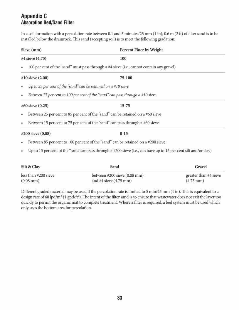
Appendix CAbsorption Bed/Sand Filter
In a soil formation with a percolation rate between 0.1 and 5 minutes/25 mm (1 in), 0.6 m (2 ft) of filter sand is to be installed below the drainrock. This sand (accepting soil) is to meet the following gradation:
Sieve (mm) Percent Finer by Weight
#4 sieve (4.75) 100
• 100 per cent of the “sand” must pass through a #4 sieve (i.e., cannot contain any gravel)
#10 sieve (2.00) 75-100
• Up to 25 per cent of the “sand” can be retained on a #10 sieve
• Between 75 per cent to 100 per cent of the “sand” can pass through a #10 sieve
#60 sieve (0.25) 15-75
• Between 25 per cent to 85 per cent of the “sand” can be retained on a #60 sieve
• Between 15 per cent to 75 per cent of the “sand” can pass through a #60 sieve
#200 sieve (0.08) 0-15
• Between 85 per cent to 100 per cent of the “sand” can be retained on a #200 sieve
• Up to 15 per cent of the “sand’ can pass through a #200 sieve (i.e., can have up to 15 per cent silt and/or clay)
Silt & Clay Sand Gravel
less than #200 sieve between #200 sieve (0.08 mm) greater than #4 sieve(0.08 mm) and #4 sieve (4.75 mm) (4.75 mm)
Different graded material may be used if the percolation rate is limited to 5 min/25 mm (1 in). This is equivalent to a design rate of 60 lpd/m² (1 gpd/ft²). The intent of the filter sand is to ensure that wastewater does not exit the layer too quickly to permit the organic mat to complete treatment. Where a filter is required, a bed system must be used which only uses the bottom area for percolation.
DESIGN SPECS FOR SEWAGE DISPOSAL SYSTEMS JUNE 2016.indd 33 2016-07-04 1:30 PM
34
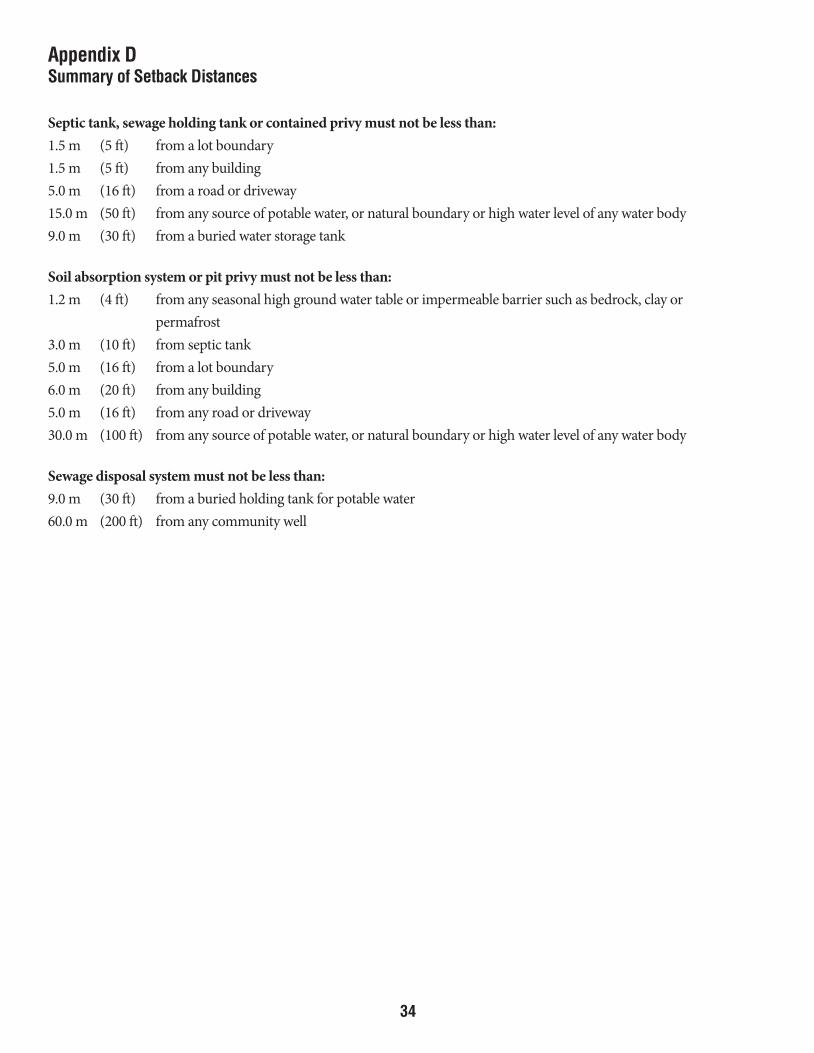
Appendix DSummary of Setback Distances
Septic tank, sewage holding tank or contained privy must not be less than:1.5 m (5 ft) from a lot boundary1.5 m (5 ft) from any building5.0 m (16 ft) from a road or driveway15.0 m (50 ft) from any source of potable water, or natural boundary or high water level of any water body9.0 m (30 ft) from a buried water storage tank
Soil absorption system or pit privy must not be less than:1.2 m (4 ft) from any seasonal high ground water table or impermeable barrier such as bedrock, clay or permafrost3.0 m (10 ft) from septic tank5.0 m (16 ft) from a lot boundary6.0 m (20 ft) from any building5.0 m (16 ft) from any road or driveway30.0 m (100 ft) from any source of potable water, or natural boundary or high water level of any water body
Sewage disposal system must not be less than:9.0 m (30 ft) from a buried holding tank for potable water60.0 m (200 ft) from any community well
DESIGN SPECS FOR SEWAGE DISPOSAL SYSTEMS JUNE 2016.indd 34 2016-07-04 1:30 PM
35
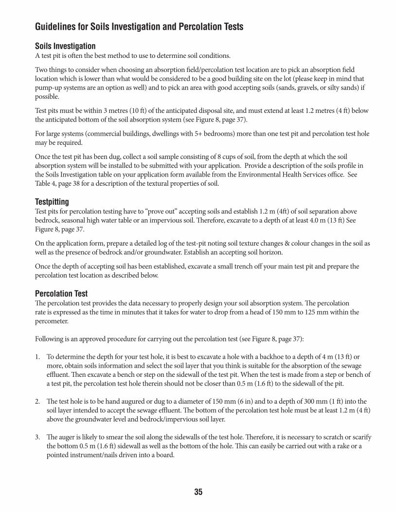
Guidelines for Soils Investigation and Percolation Tests
Soils InvestigationA test pit is often the best method to use to determine soil conditions.
Two things to consider when choosing an absorption field/percolation test location are to pick an absorption field location which is lower than what would be considered to be a good building site on the lot (please keep in mind that pump-up systems are an option as well) and to pick an area with good accepting soils (sands, gravels, or silty sands) if possible.
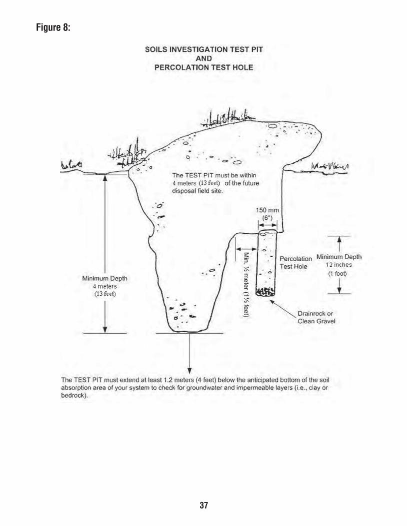
Test pits must be within 3 metres (10 ft) of the anticipated disposal site, and must extend at least 1.2 metres (4 ft) below the anticipated bottom of the soil absorption system (see Figure 8, page 37).
For large systems (commercial buildings, dwellings with 5+ bedrooms) more than one test pit and percolation test hole may be required.
Once the test pit has been dug, collect a soil sample consisting of 8 cups of soil, from the depth at which the soil absorption system will be installed to be submitted with your application. Provide a description of the soils profile in the Soils Investigation table on your application form available from the Environmental Health Services office. See Table 4, page 38 for a description of the textural properties of soil.
TestpittingTest pits for percolation testing have to “prove out” accepting soils and establish 1.2 m (4ft) of soil separation above bedrock, seasonal high water table or an impervious soil. Therefore, excavate to a depth of at least 4.0 m (13 ft) See Figure 8, page 37.
On the application form, prepare a detailed log of the test-pit noting soil texture changes & colour changes in the soil as well as the presence of bedrock and/or groundwater. Establish an accepting soil horizon.
Once the depth of accepting soil has been established, excavate a small trench off your main test pit and prepare the percolation test location as described below.
Percolation TestThe percolation test provides the data necessary to properly design your soil absorption system. The percolation rate is expressed as the time in minutes that it takes for water to drop from a head of 150 mm to 125 mm within the percometer.
Following is an approved procedure for carrying out the percolation test (see Figure 8, page 37):
1. To determine the depth for your test hole, it is best to excavate a hole with a backhoe to a depth of 4 m (13 ft) or more, obtain soils information and select the soil layer that you think is suitable for the absorption of the sewage effluent. Then excavate a bench or step on the sidewall of the test pit. When the test is made from a step or bench of a test pit, the percolation test hole therein should not be closer than 0.5 m (1.6 ft) to the sidewall of the pit.
2. The test hole is to be hand augured or dug to a diameter of 150 mm (6 in) and to a depth of 300 mm (1 ft) into the soil layer intended to accept the sewage effluent. The bottom of the percolation test hole must be at least 1.2 m (4 ft) above the groundwater level and bedrock/impervious soil layer.
3. The auger is likely to smear the soil along the sidewalls of the test hole. Therefore, it is necessary to scratch or scarify the bottom 0.5 m (1.6 ft) sidewall as well as the bottom of the hole. This can easily be carried out with a rake or a pointed instrument/nails driven into a board.
DESIGN SPECS FOR SEWAGE DISPOSAL SYSTEMS JUNE 2016.indd 35 2016-07-04 1:30 PM

36
4. Remove all loose soil material from the bottom of the test hole, and then add 50 mm (2 in) of 6 to 20 mm (1/4 to 3/4 in) diameter drainrock to protect the bottom from scouring when water is added. The gravel can be contained in a nylon mesh bag to be removed after the test is performed for use in additional percolation tests.
5. Carefully fill the test hole with clean water to at least 300 mm (12 in) in depth, and continue to do so until the soil is saturated. Saturation means that the void spaces between the soil particles are full of water. Keep soaking the hole until the rate at which the water seeping away becomes constant.
In the event that the soil layer consists mainly of:
(a) heavy silts or clays, then water must be kept in the hole to allow for saturation and swelling. Keep water in the hole for at least 4 hours, preferably overnight. Refill, if necessary, or supply a surplus reservoir of water, maintaining the 300 mm (12 in) depth with an automatic siphon. Use a hose or similar device to add water to the hole and to prevent washing down the sides of the hole. Measure the percolation rate after at least 16 hours, but no more than 30 hours after water was first added to the hole. This ensures that the soil has an ample opportunity to swell and to approach the natural condition during the wettest season.
(b) sand and gravel, and you are unable retain water in the hole after attempting to saturate the soil, then you may assume that your rate of percolation is less than 5 min./25 mm (1 in). Should this be the case, then 0.6 m (2 ft) of filter sand may be required. Refer to Appendix C, page 33, for sand filter specifications.
6. Stand the percometer up in the hole and support it with cobbles. A bed of small stones under the percometer is important to allow free flow of water.
7. Make sure the float and measuring device accompanying the percometer are in place and working. As water is poured down throughout the percometer, the float will come up. Fill the percolation test hole you excavated in your trench and keep it full during the pre-soak period (4 hours for fine grained soils – 10 gallons of water for sand and gravel).
8. The percolation rate is the amount of time it takes for the water to drop from a head of 150 mm (6 in) to 125 mm (5 in) within the percometer, so after your pre-soak is completed, fill the percometer to 150 mm and measure the amount of time it takes to drop to 125 mm. Record the time, repeat the test as necessary and record the results on your application. Continue taking readings until three consecutive percolation rates vary by no more than 10 per cent. Those are the numbers that are to be submitted.
See page 10 now for the sizing of your absorption system.
DESIGN SPECS FOR SEWAGE DISPOSAL SYSTEMS JUNE 2016.indd 36 2016-07-04 1:30 PM
3733
Figure 7 :Figure 8:
DESIGN SPECS FOR SEWAGE DISPOSAL SYSTEMS JUNE 2016.indd 37 2016-07-04 1:30 PM

3834
TABLE 4TEXTURAL PROPERTIES OF SOILS
Feeling and Appearance
Soil Class Dry Soil Moist Soil
SandyGravel
Loose stones and single grains which feel gritty. Squeezed in the hand, the soil mass falls apart when the pressure is released.
Squeezed in the hand, it forms a cast which crumbles when touched. Does not form a ribbon between thumb and forefinger.
SiltySand
Aggregates easily crushed; very faint velvety feeling initially but with continued rubbing, the gritty feeling of sand soon dominates.
Forms a cast which bears careful handling without breaking. Does not form a ribbon between the thumb and forefinger.
SandySilt
Aggregates are crushed under moderate pressure; clods can be quite firm. When pulverized, soil has velvety feel that becomes gritty with continued rubbing. Casts bear careful handling.
Cast can be handled quite freely without breaking. Very slight tendency to ribbon between the thumb and forefinger. Rubbed surface is rough.
ClayeySilt
Aggregates are firm but may be crushed under moderate pressure. Clods are firm to hard. Smooth, flour-like feel dominates when soil is pulverized.
Cast can be freely handled without breaking. Slight tendency to ribbon between the thumb and forefinger. Rubbed surface has a broken or rippled appearance.
SiltyClay
Very firm aggregates and hard clods that strongly resist crushing by hand. When pulverized, the soil takes on a somewhat gritty feeling due to the harshness of very small aggregates which persist.
Cast can bear much handling without breaking. Pinched between the thumb and forefinger, it forms a ribbon whose surface tends to feel slightly gritty when dampened and rubbed. Soil is plastic, sticky and puddles easily.
Clay Aggregates are hard; clods are extremely hard and strongly resist crushing by hand. When pulverized, it has a grit-like texture due to the harshness of numerous verysmall aggregates which persist.
Casts can bear considerable handling without breaking. Forms a flexible ribbon between the thumb and forefinger and retains its plasticity when elongated. Rubbed surface has a very smooth, satin feeling. Sticky when wet and easily puddles.
Table 4:Textural Properties of Soil
Feeling and Appearance
DESIGN SPECS FOR SEWAGE DISPOSAL SYSTEMS JUNE 2016.indd 38 2016-07-04 1:31 PM

39
Photographic Record Submission Requirements of the stages of Installation of a Sewage Disposal System
The Sewage Disposal Systems Regulation requires a photographic record of the stages of installation to be submitted to a Health Officer within 30 days of installation of the sewage disposal system.
All photographs must be marked with the permit number and the legal description of the property on which the sewage disposal system was installed. Please refer to the list below and add the relevant number from the list to the photograph so as to confirm what was installed. Several listed items may be shown in a single photograph; in such case please add all relevant numbers to that photograph.
Delays in issuing Approval to Use may occur if the photographs do not clearly depict the installation of the sewage disposal system, or if the record is incomplete.
Regardless of whether or not a health officer is present during system installation, the photographic submission requirements must be met.
Septic Tanks and Sewage Holding Tanks
If a septic tank or sewage holding tank will be installed, submit a picture depicting the:1. Excavation with bedding material at base (prior to placement of tank).2. Excavation containing the septic tank or sewage holding tank.3. Volume marking(s) on the septic tank or sewage holding tank (e.g., stencil on the tank).4. Bedding material (e.g., pea gravel) surrounding tank.5. Certification marking or label on septic tank or sewage holding tank (e.g., CAN/CSA-B66).6. Trench between septic tank or sewage holding tank and the building to which it will be/is connected–must show
pipe in place with flex coupling. 7. The septic tank or sewage holding tank covered with soil to original ground level showing all clean-outs and
observation pipes, and relationship to building that it services (if present) or other distinguishing permanent landmark(s).
If a septic tank will be installed, also submit a picture depicting the:8. Pipe with flex coupler in place in trench between septic tank and soil absorption system (e.g., absorption bed,
trenches).
If a sewage holding tank will be installed, also submit a picture depicting the:9. High level alarm and automatic water shut-off.10. Floats attached to float tree within the tank.
If the tank will be installed in a location with high ground water or an area prone to flooding, submit a picture depicting the:11. Anchoring harnesses, turnbuckles, and cables in place and attached to tank.12. “Deadmen” or concrete pad used for anchoring purposes.
DESIGN SPECS FOR SEWAGE DISPOSAL SYSTEMS JUNE 2016.indd 39 2016-07-04 1:31 PM

40
Soil Absorption SystemIf a soil absorption system will be installed, submit a picture depicting the:13. Excavation for the soil absorption system that shows the soil profile.
If installing a soil absorption system in “fast soils” (less than 5 minutes per inch percolation rate) submit a picture depicting the:14. Filter sand and its depth–a tape measure or similar device must appear in the picture.
If installing a soil absorption system using drain rock, submit a picture depicting the:15. Drain rock and its depth–a tape measure or similar device should appear in the picture. For trenches, show width and
depth. 16. Perforated pipe(s) (the total length must be clear and easy to determine) laid out on the drain rock–if installed in
sections, a picture of each stage of installation of the pipe must be provided.17. Perforated pipe(s) covered with drain rock.18. Drain rock covered with geotextile or rigid insulation (e.g., Styrofoam).
If installing a soil absorption system using chambers, submit a picture depicting the:19. Chambers (the area and width must be clear and easy to determine)–if installed in sections, a picture of each stage of
installation of the chambers must be provided.20. Layer of geotextile cloth laid beneath first section of chamber (unless a pipe or other method used, if so provide photo
showing that).21. Monitor and clean-out pipes in place extending from chambers. 22. Header pipe feeding each chamber run.23. Soil absorption system covered with soil to original ground level showing all clean-outs, observation pipes, and
relationship to building that it services (if present) or other distinguishing permanent landmark(s).
Pump-Up and Raised Soil Absorption Systems
If the sewage disposal system is to contain a mechanical pump (inside your septic tank) that discharges sewage to a raised soil absorption system, submit a picture depicting the:24. Force-main exiting man-way.25. Anti-siphon device.26. Pump on mount or stand after installation in septic tank.27. Mounded or otherwise elevated force-main (to ensure liquids don’t pool).28. Insulation of the force-main (if/when burial depth is less than four feet).29. Frost plug-in man-way (if frost plug completed). 30. Floats in place attached to float tree.31. Warning indicator system and automatic water shut-off systems in place (on the mounting stand or within the
building).
Please include photographs that show any part of the installation of the sewage disposal system not described above.
DESIGN SPECS FOR SEWAGE DISPOSAL SYSTEMS JUNE 2016.indd 40 2016-07-04 1:31 PM

41
Application Submission RequirementsPlease be advised that applications must be received at least 48 hours in advance of planned receipt of the permit. The permit must be issued prior to installation of system.
As a minimum, the following must be submitted to Environmental Health Services along with an applicationfor a permit to install a septic system: • A sketch showing a profile of the system layout, including septic tank, and absorption system plus a plan
showing the location and horizontal distances between all system components, water supply, and structures. • An 8-cup soil sample from the percolation test hole from the depth at which the soil absorption system will be
installed.• Where applicable, the pump-up system design rationale and specifications for: - pump selection - controls (level switch settings) - forcemain (type, diameter, class, insulation) - height and distance for effluent transfer from tank to absorption system Once a permit has been issued there can be no alteration to the sewage disposal system or other work it refers
to without the approval of a Health Officer.11 Sewage Disposal Systems Regulation
Getting Your System ApprovedWithin 30 days of the installation of the system, the following information shall be provided to a Health Officer: • Photographic record of the stages of installation • Completion of the Notification of Installation and Undertaking to Maintain a Sewage Disposal System • Other documentation as requested by the Health Officer (Tank CSA approval, Septic Tank Installation
Declaration form, Abandonment and Reclamation document, Receipts)
Approval to Use a Sewage Holding Tank requires the following to be submitted for review by a Health Officer: • Septic Tank and Sewage Holding Tank Installation Declaration form; • photographs of the stages of installation; • receipt or other form of proof from a qualified electrical contractor or certified electrician (for high level alarm
and automatic water shut-off); and • Notification of Installation and Undertaking to Maintain a Sewage Holding Tank form.
Provided that the Health Officer is satisfied that all requirements have been met, written approval to use the sewage disposal system shall be issued by the Health Officer.
13(2) Sewage Disposal Systems Regulation
DESIGN SPECS FOR SEWAGE DISPOSAL SYSTEMS JUNE 2016.indd 41 2016-07-04 1:31 PM

42
Water, Sewage And Environmental Health
Properly operating septic systems are a good way to control waterrelated disease. Bacteria, viruses and parasites found in sewage are the principal causes of water-related disease, such as various gastrointestinal illnesses, hepatitis A and Giardiasis (Beaver Fever). Sewage from toilets is classified as black water and all other domestic sewage–for example, wastewater from the shower, kitchen sink, washing machine, etc.–is referred to as grey water.
Both grey and black water can be expected to contain significant numbers of disease-causing microorganisms. Some people believe that grey water can bypass the septic tank or other sewage treatment system, but this tends to ignore the characteristics of such waste. Grey water typically contains between one and three million faecal coliforms and between three and ten thousand Faecal Streptococci microorganisms per 100 ml. These “indicator” types confirm the potential presence of a wide range of disease-causing microorganisms originating in the intestines of humans and animals. Additionally, grey water tends to have sufficiently high levels of suspended solids and fat that, without pretreatment, nuisance conditions can result and health risks arise when it is discharged into the ground.
Full treatment of septic tank effluent requires that it be discharged into the unsaturated soil zone. This discharge, at an appropriate rate, will fully utilize the treatment available through filtration and chemical/ biological breakdown processes. Disease-causing organisms can survive for longer periods during prolonged cold spells in the Yukon. Their containment and eventual breakdown beneath the ground surface protects human and animal health. Travel through one to two feet of unsaturated silty, sandy, or clay loam soil can be expected to remove the sewage microorganisms, and protect ground and surface water. Protection of the environment and the public health is further enhanced because of the required set-back distances, the safety zones established for surface water, wells and property lines. Soil conditions vary and a greater unsaturated soil depth and/or a sand filter is required in coarse, granular soils. In the Yukon, many areas are suitable for soil absorption systems. However, there are some situations where they cannot be used. Factors preventing installation include lot size, soil type, and the proximity of bedrock, high water table or permafrost.
The septic system should receive all discharges from toilets, and the waste from baths, washbasins, showers, sinks and washing machines. Surface water from roofs, yards and foundation drainage, together with spring run-off, must be excluded from the septic tank and absorption bed area.
ADDENDUM: Septic Systems in the Yukon – A Guide to their Design and Maintenance (2006)
DESIGN SPECS FOR SEWAGE DISPOSAL SYSTEMS JUNE 2016.indd 42 2016-07-04 1:31 PM

43
How a Septic System Works
A septic system consists of two main components: a septic tank and a soil absorption system.
A septic tank is a two-compartment, watertight container which is used to pretreat household sewage (black and grey water) before it enters the soil absorption system. The sewage stays in the first compartment long enough to enable the heavier solids to settle out to the bottom and the lighter solids, including fats and grease, to rise to the surface and form a scum layer. The retained sludge and scum undergo partial digestion and conversion to a liquid form acceptable to the receiving ground. A properly designed and maintained septic tank can remove most of the settleable solids before it is discharged into the soil absorption system.
A siphon chamber, which is usually incorporated in the tank, stores the effluent and intermittently discharges it to the absorption system in large flushes. The owner should inspect the septic tank to ensure that the baffles have been properly installed and test the siphon before it is backfilled.
The septic tank must meet the appropriate CSA standard.
DESIGN SPECS FOR SEWAGE DISPOSAL SYSTEMS JUNE 2016.indd 43 2016-07-04 1:31 PM

44
Soil Absorption Systems
Two main types of soil absorption systems are used in the Yukon: the absorption bed, and the absorption trench. Due to cold winter climatic conditions, both the septic tank and the soil absorption system (if uninsulated) require a minimum soil cover of 1.2 m (4’).
Absorption BedAn absorption bed is a rectangular excavation containing 300 mm (12”) of drain rock, perforated pipes, geotextile and standpipes that receive septic tank effluent. Absorption occurs only through the bottom of the bed.
DESIGN SPECS FOR SEWAGE DISPOSAL SYSTEMS JUNE 2016.indd 44 2016-07-04 1:31 PM
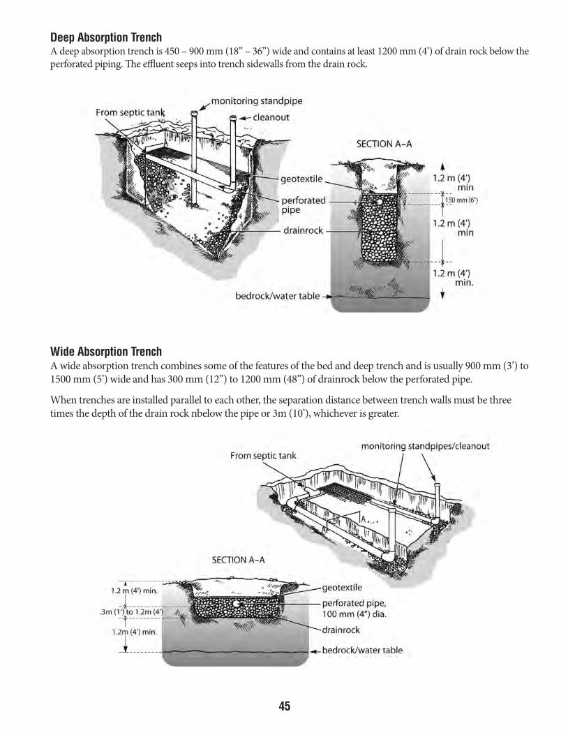
45
Deep Absorption TrenchA deep absorption trench is 450 – 900 mm (18” – 36”) wide and contains at least 1200 mm (4’) of drain rock below the perforated piping. The effluent seeps into trench sidewalls from the drain rock.
Wide Absorption TrenchA wide absorption trench combines some of the features of the bed and deep trench and is usually 900 mm (3’) to 1500 mm (5’) wide and has 300 mm (12”) to 1200 mm (48”) of drainrock below the perforated pipe.
When trenches are installed parallel to each other, the separation distance between trench walls must be three times the depth of the drain rock nbelow the pipe or 3m (10’), whichever is greater.
DESIGN SPECS FOR SEWAGE DISPOSAL SYSTEMS JUNE 2016.indd 45 2016-07-04 1:31 PM
46
Design and InstallationBefore designing a septic system, it is essential that complete and accurate site investigations are carried out. This is important to determine whether a lot is suitable for onsite disposal. For new house construction, these investigations should be carried out before the house design is completed in order to ensure that the house location is suited to the septic system location, thereby allowing you to determine the most cost effective design. The site investigation shouldinclude the following:
• Location and setback distances (see opposite page)• Soil conditions (soil type and percolation rate)• Surface features (ground slope, rock outcrops, traffic areas, etc.)• Provision for expansion or replacement of septic system• Depth to groundwater and bedrock (minimum vertical clearance from bottom of absorption system to
groundwater is 1.2 m (4 ft.))
The percolation rate is a measure of the soil’s ability to absorb liquid and is the single most important parameter used for sizing a soil absorption system. The percolation test must be performed according to procedures specified, a copy of which is available from Environmental Health Services.
In the Yukon, many areas are suitable for soil absorption systems. However, there are some conditions which will prevent the installation of such a system. These include fine grained soils (very slow percolation rate), inadequate lotsize, permafrost, inadequate distance to natural water bodies, and insufficient vertical clearances to bedrock and/or groundwater.
DesignDesigns for septic systems can be completed by the homeowner, contractor or engineering consultant. Detailed information and advice, if required, is available from the Environmental Health Office in Whitehorse. A Permit to Install a Sewage Disposal System is required prior to the installation, modification or upgrading of any septic system. Developers should also check with local municipal requirements. A sewage disposal permit is required before a building permit may be issued by Building Inspectors for the Yukon Government or the City of Whitehorse.
InstallationIt is very important that a septic system be installed carefully and in strict accordance with the approved design. Failure to do so may result in problems with the system. The septic tank must be installed and suitably bedded, design grades for building sewers must be adhered to, and care must be taken to ensure the absorption bed components are installed according to the approved design. Further information and owner’s responsibilities are outlined in “Application and Permits”.
DESIGN SPECS FOR SEWAGE DISPOSAL SYSTEMS JUNE 2016.indd 46 2016-07-04 1:31 PM
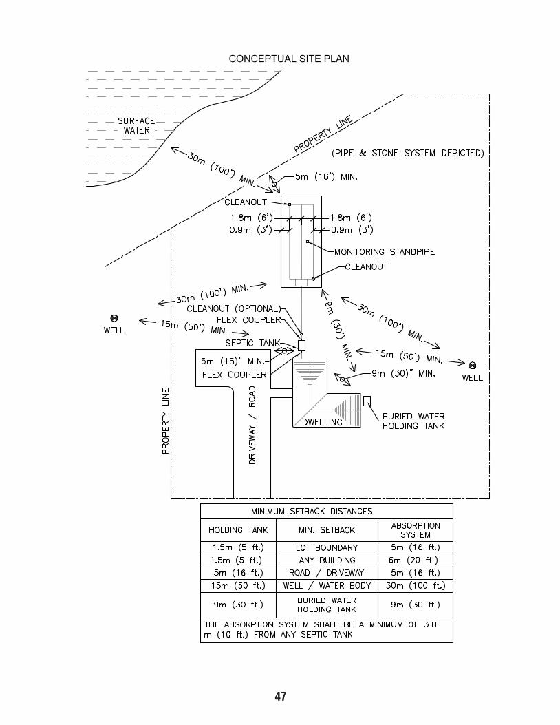
47
DESIGN SPECS FOR SEWAGE DISPOSAL SYSTEMS JUNE 2016.indd 47 2016-07-04 1:31 PM

48
Operation and MaintenanceA sewage system which has been properly installed should, with proper care and maintenance, provide many years of service. There are, however, some things which you, the homeowner, should be aware of that will help the system to function properly. These are:
1. Surface Water Do not allow roof drains to discharge to the septic tank or surface waters to drain towards the area of the disposal
field.
2. Water Usage Excessive and unnecessary water usage should be kept to a minimum in the home. If automatic washers and
dishwashers are used, make sure full loads are washed each time. Excessive use of water, such as doing numerous washings in one day, could flush solids from the tank to the disposal field.
3. Garbage Disposal Units Wastes from garbage disposal units are not easily digested by bacteria in the septic tank and only add to the volume
of solids in the septic tank which must be removed by pumping the tank. Therefore, the use of garbage disposal units is not recommended.
4. Operation Moderate use of household drain solvents, cleaners, disinfectants, etc. should not interfere with the operation of
the sewage disposal system, but indiscriminate use may cause problems. Toilet paper substitutes, paper towels, newspaper, sanitary napkins, etc. should not be flushed into the septic tank since they will not readily decompose.
5. Starters and Cleaners There is no need to use commercial “starters”, “bacterial feeds”, or “cleaners” for the septic tank or disposal field.
Some additives can actually create problems by causing solids to be carried into the absorption system, resulting in soil clogging.
6. Inspection and Cleaning The septic tank should be inspected once every year and the tank pumped out when necessary. As a minimum, the
tank should be cleaned every two years. Failure to pump out a septic tank when required may result in sludge or scum being carried over to the disposal field, resulting in soil clogging and complete failure of the system. The tank should not be washed or disinfected after pumping. The cleaning should be performed by professionals familiar with proper procedures and having adequate equipment.
7. Vegetation The area over a disposal field should have a good vegetation cover. However, shrubs or trees should not be planted
over the area in order to allow the system to be kept open to sunlight.
8. Increased Waste Loads If the waste loads and volumes of sewage entering the soil absorption system are greater than that for which
the system was designed, failure of the field can occur. Contact the Environmental Health Office regarding enlargement/repair/replacement options.
DESIGN SPECS FOR SEWAGE DISPOSAL SYSTEMS JUNE 2016.indd 48 2016-07-04 1:31 PM

49
9. Vents and Accesses During the winter, airtight caps should be securely fastened on all cleanouts and monitoring pipes. These pipes
should also be fitted with insulation plugs to help discourage the escape of heat from the soil absorption system.
10. Traffic Over Absorption System The area above and near a soil absorption system should never be used as a traffic area for vehicles or pedestrians.
An accumulation of snow is important in order to maintain a cover of natural insulation to prevent freezing. During winter months, it is recommended that a snow fence or other suitable barrier be placed around the absorption system to discourage any traffic on the area. This will help maintain a thicker layer of snow insulation over the area.
11. Periodic Occupancy If the residence is used only periodically, or if extended absences occur, freezing problems can develop in the winter.
Extra insulation (i.e. leaves, straw, sawdust, snow) over the system can help to reduce the freezing potential. When the house will be vacant for extended time periods, and there is a potential for freezing, it is advisable to have the septic tank emptied.
12. As-Built Plans A detailed diagram showing the exact location of the septic tank and disposal field should be placed in a suitable
location in the home for future reference along with the application, final approval certificate, and photos of the installation. This documentation can also be helpful when selling the property at a later date.
DESIGN SPECS FOR SEWAGE DISPOSAL SYSTEMS JUNE 2016.indd 49 2016-07-04 1:31 PM

50
Application and PermitsWhen you are planning to build a home on a property where there are no piped sewage services available, you must adhere to the regulations pursuant to the Public Health and Safety Act. Below is listed an outline of steps that would normally be followed from the time you have decided to install a septic system to completion of the installation.
1. Contact the Environmental Health Office to pursue your application requirements (i.e. application forms, standards, guidelines, etc.).
2. Carry out site investigations required to determine the suitability of your property for a septic system. This includes location and setback requirements, soils conditions (percolation test and soils investigations), surface features, and provisions for replacement or expansion. This can be done by the homeowner, contractor or engineering consultant.
3. Complete a septic system design and submit the necessary Permit Application to the Environmental Health Office. The Environmental Health Officer can guide you through the application process. If all necessary data is supplied and the proposed system is judged suitable, a Permit to Install a Sewage Disposal System will be issued. Note that the permit is also subject to compliance with federal, territorial and municipal laws, including subdivision prospectus agreements.
4. After the sewage disposal permit has been issued, a building permit for new house construction may be issued by the municipal or territorial government. An occupancy permit will not be issued by the Building Department until final approval to use the septic system is obtained from the Environmental Health Office.
5. Photographs must be taken, depicting each stage of the installation and as-built drawings of the system must be prepared. This includes photos of the excavation, drain rock placement (showing depth and quality), all piping, geotextile plus the septic tank prior to final backfilling. Such photos should be properly identified and dated.
6. Before backfilling a septic system, the owner or agent must contact the Environmental Health Office at least 72 hours before a final inspection is required. If the installation has been carried out properly, approval will be given to the owner in writing.
7. After construction, the owner must sign and submit a Notification of Installation and Undertaking to Maintain a Septic Tank and Soil Absorption System, together with copies of the photographs.
Records of installation and a letter of approval will help in future sale of the property and in the processing of financing arrangements.
DESIGN SPECS FOR SEWAGE DISPOSAL SYSTEMS JUNE 2016.indd 50 2016-07-04 1:31 PM

51
Glossary
Chemical and A natural treatment process whereby sewage is converted to other materials which are lessBiological Breakdown harmful to humans and the environment.
Drainrock Clean gravel, 20 to 65 mm (3/4 to 2-1/2”) in diameter, with no more than 3 per cent fines (0.080 mm) residual after screening. These specifications must be adhered to for final approval of soil absorption systems.
Faecal Coliforms A large group of bacteria which normally thrive in the intestines of warm-blooded animals including humans. Their presence indicates recent sewage contamination.
Geotextile An approved permeable filter fabric which prevents mixing of finer soil materials with the underlying drainrock.
Microorganisms Organisms which cannot be seen with the naked eye, e.g. bacteria, viruses, and certain parasites.
Percolation Rate The time rate of water drop in a test hole expressed as minutes per 25 mm (1’’). The percolation rate must be determined in accordance with procedures specified by Environmental Health Services. It is a measure of the soil’s ability to absorb liquid and is the single most important parameter used to size a soil absorption system.
Sand Filter Fine sand/silt material that has a percolation rate of 5 minutes/25 mm (1”) or slower. In course, granular soils having a rapid percolation rate, a sand filter 600 mm (2 feet) deep must be installed to reduce the rate of effluent percolation through the soil to ensure adequate soil treatment of the effluent.
Septic Tank Effluent The liquid that flows out from a septic tank.
Set Back A separation distance, measured horizontally.
Soil Absorption A subsurface disposal system used to absorb effluent from the septic tank. Two main types of System systems are the absorption bed and the absorption trench.
For more information on sewage disposal systems in Yukon, please contact:
Environmental Health Services#2 Hospital RoadWhitehorse, Yukon Y1A 3H8Phone: (867) 667-8391Toll-free (within Yukon) 1-800-661-0408, ext. 8391Fax: (867) 667-8322E-mail: [email protected]
DESIGN SPECS FOR SEWAGE DISPOSAL SYSTEMS JUNE 2016.indd 51 2016-07-04 1:31 PM

52
Construction of a Septic System in Dredge Tailings The construction of an absorption bed over a sufficient thickness of suitable soil (sand/silt) provides ample treatment against the migration of organics and bacteria.
Isolation distances should be examined carefully with respect to the proximity of surface water and potable water supplies, given that the migration of the effluent will likely be direct due to the coarse nature of the underlying tailings (a minimum of 200 feet is recommended).
Design criteria for a septic system in dredge tailings is as per the “Design Specifications for Sewage Disposal Systems” except for the following modifications to the absorption bed:
• Minimum of 6 feet of accepting soil (sand/silt with a percolation rate of 5 min./25 mm [1 in.] or slower) is to be provided beneath the drain rock.
• Accepting soil is to extend a minimum of 6 feet horizontally from the distribution pipes, continuing a minim depth of 6 feet.
• Geotextile is to be placed under the accepting soil at the dredge tailings interface and extend on all sides up to the upper layer of the geotextile.
• Finish grade over the bed must be mounded to exceed 2 feet beyond the edge of the extended absorption bed area to ensure the diversion of surface water.
EXAMPLE:6’
6’
6’
6’
6’
6’6’
SEPTICTANK
SIPHON
CLEAN OUT STAND PIPE
MONITORINGSTAND PIPE
MOUND
GEOTEXTILE
GEOTEXTILE
2’ 2’
MINIMUM 6’ ACCEPTING SOIL(SAND/SILT)
1’ DRAIN ROCK3/4” TO 2” WASHED ROCK
MINIMUM 4’
DESIGN SPECS FOR SEWAGE DISPOSAL SYSTEMS JUNE 2016.indd 52 2016-07-04 1:31 PM

53
DESIGN SPECS FOR SEWAGE DISPOSAL SYSTEMS JUNE 2016.indd 53 2016-07-04 1:31 PM

Health and Social ServicesISBN 978-1-55362-699-2UPDATED JUNE 2016
DESIGN SPECS FOR SEWAGE DISPOSAL SYSTEMS JUNE 2016.indd 54 2016-07-04 1:31 PM
ISBN 978-1-55362-699-2 UPDATED APRIL 2017
2Hosp_Doc_SewageDisposalSystems_85238d_BackCover.indd 1 2017-03-23 2:57 PM