Embed Size (px)
Citation preview

March 5th, 2009 Mr. Patrick Leung School of Engineering Science Simon Fraser University 8888 University Drive Burnaby BC V5A 1S6 Re: ENSC440 Design Specification for the License Plate Recognition Auto-gate System Dear Mr. Leung: The attached document, Design Specification for a License Plate Recognition (LPR) Auto-gate System, outlines the system behavior of our project for ENSC 440 (Capstone Engineering Science Project). Our goal is to design and implement an auto-gate system for residential parking lots, using the LPR technology, which captures a license plate image of a vehicle and verifies its registration status by post digital image processing for the parking lot access control. The purpose of the document is to describe design specifications of our system regarding three main parts: metal detector, LPR algorithm, and microcontroller board. The method and design of the parts will be discussed in detail, which apply to the proof-of-concept system only. The test plans for each module will be provided in the document as well. Seco Innovations Corporation consists of three talented 5th year Engineering students: Danny Choi, Wook Sun Shim, and Jaehoon Shin. Gathering various knowledge and strength from our disciplines in Electronics and Systems options and from industrial co-op work experiences, we are here to challenge on the project that can replace the current solution by providing better security and convenience to the public. If you have any questions regarding our proposal, please feel free to contact me by phone at 604-996-6012 or by e-mail at [email protected]. Sincerely,
Danny Choi President and CEO Seco Innovations Corporation Enclosure: Design Specification for a License Plate Recognition (LPR) Auto-gate System

i Copyright © 2009, Seco Innovations Corporation
Design Specification
License Plate Recognition (LPR) Auto-gate System
Project Team: Danny Chol Wook Sun Shim Jaehoon Shin
Contact Person: Danny Choi [email protected]
Submitted to: Patrick Leung – ENSC 440 Steve Whitmore – ENSC 305 School of Engineering Science Simon Fraser University
Issued Date: March 5th, 2009
Revision: 2.1

ii Copyright © 2009, Seco Innovations Corporation
Executive Summary The LPR auto-gate system is described in detail as to its design specifications. The three main parts of the system: metal detector, LPR algorithm, and microcontroller for verification display are introduced with their methods and design details for the development of the proof of concept system. Thus, the part I and II requirements from the functional specification will be discussed in order to design the system pertaining to the requirements. The metal detector consists of inductor sensor and operational amplifiers as an integrated circuit that can detect metal and it will trigger the camera to capture an image of the license plate. The overall electrical design and the assembled circuit will be introduced with diagrams. The LPR algorithm consists of three main parts that are required to successfully recognize license plate number in ASCII characters: license plate localization, skew correction, and character recognition. The approaching vehicle will be captured triggered by metal detector in various random positions. The captured image will include the whole vehicle, thus the plate localization is required for further image processing. The localized plate will go through character segmentation for each character so as to recognize them by template matching. Using the horizontal and vertical projection, the each character will be segmented and their vertical projection sum will be matched with pre-defined templates. The microcontroller module is a communication bridge between the computer and the metal detector. Using LED and LCD screen, it will display the verification status output of the system. Thus, a control algorithm will be applied and the further design and usage details will be discussed. For all of the modules above, the test plan for each and for an integrated system will be provided in this document. The design choices, flow chart of certain processes will be discussed as well. The completion of the first demonstrational system is expected to be in the first week of April 2009.

iii Copyright © 2009, Seco Innovations Corporation
Table of Contents Executive Summary ......................................................................................................... ii
List of Figures .................................................................................................................. v
List of Tables ................................................................................................................... v
List of Equations .............................................................................................................. v
Acronyms ........................................................................................................................ vi
Glossary ......................................................................................................................... vii
1. Introduction ................................................................................................................. 1
1.1. Scope .............................................................................................................................. 1
1.2. Intended Audience ........................................................................................................... 1
2. System Overview ........................................................................................................ 2
3. Metal Detector Module ................................................................................................ 4
3.1. Electrical Design .............................................................................................................. 4
3.1.1. Actuator and Sensor Pair .......................................................................................... 5
3.1.2. Band-Pass Filter ........................................................................................................ 5
3.1.3. Power Detector ......................................................................................................... 6
3.1.4. Differentiator ............................................................................................................. 6
3.1.5. Schmitt Trigger .......................................................................................................... 7
3.2. Assembled circuit ............................................................................................................ 8
4. Microcontroller Module .............................................................................................. 10
4.1. Atmega168 Chip Overview .............................................................................................10
4.2. Other Electronics on Module ...........................................................................................11
4.2.1 Power Supply ............................................................................................................11
4.2.2 LCD Display ..............................................................................................................11
4.2.3. Programming Header Using a Serial to USB cable ..................................................13
4.3. Integration with the Metal Detector and the Local Computer ...........................................13
4.3.1 Integration with the Metal Detector ............................................................................13
4.3.2. Integration with the Local Computer .........................................................................14
5. License Plate Recognition (LPR) Module .................................................................. 16
5.1. Camera Module ..............................................................................................................16
5.2. License Plate Localisation ..............................................................................................17

iv Copyright © 2009, Seco Innovations Corporation
5.3. Skew Correction .............................................................................................................18
5.4. Letter Recognition ..........................................................................................................19
5.5. Verification Module .........................................................................................................21
6. System Test Plan ...................................................................................................... 22
6.1. Hardware Testing ...........................................................................................................22
6.2. License Plate Recognition Module Testing .....................................................................22
6.2.1. Camera Module Testing ...........................................................................................22
6.2.2. License Plate Localisation Testing ...........................................................................23
6.2.3. Skew Correction Testing ..........................................................................................23
6.2.4. Letter Recognition Testing .......................................................................................24
6.2.5. LPR Integration Testing ............................................................................................24
6.3. Integration Testing ..........................................................................................................25
7. Conclusion ................................................................................................................ 26
8. References ................................................................................................................ 27
Appendix A – Derivation for Hardware Component Values ............................................. a
A.1. Band-Pass Filter .............................................................................................................. a
A.2. Differentiator ................................................................................................................... b

v Copyright © 2009, Seco Innovations Corporation
List of Figures
Figure 1: System Block Diagram ..................................................................................... 2
Figure 2: Block Diagram for the Metal Detector .............................................................. 4
Figure 3: Mutual Inductance ............................................................................................ 5
Figure 4: Active Band-pass Filter .................................................................................... 5
Figure 5: Power Detector ................................................................................................ 6
Figure 6: Differentiator ..................................................................................................... 7
Figure 7: Output Signal from Differentiator ...................................................................... 7
Figure 8: Schmitt Trigger ................................................................................................. 8
Figure 9: Output from Analog to Digital Convertor [5] ..................................................... 8
Figure 10: PSpice Simulation .......................................................................................... 9
Figure 11: Atmega168 Pin Configuration ...................................................................... 11
Figure 12: System Block Diagram of LPR Module and Sub-Systems ........................... 16
Figure 13: System Block Diagram of License Plate Locator .......................................... 18
Figure 14: System Flowchart for Skew Correction Module ............................................ 19
Figure 15: System Flowchart for Letter Recognition ..................................................... 20
Figure 16: System Flowchart for Verification Module .................................................... 21
Figure A1 : Band-Pass Filter ........................................................................................... a
Figure A2: Differentiator .................................................................................................. b
List of Tables Table 1: Comparison with other Microcontroller [7, 10] ................................................. 10
Table 2: Pin Configuration for LCD Panel [6] ................................................................ 12
List of Equations Equation 1: Relationship between Ripple Voltage and Diode Voltage ............................ 6
Equation A1 ..................................................................................................................... a
Equation A2 ..................................................................................................................... a
Equation A3 ..................................................................................................................... a
Equaiton A4 ..................................................................................................................... a
Equation A5 ..................................................................................................................... b
Equation A6 ..................................................................................................................... b
Equation A7 ..................................................................................................................... b
Equation A8 ..................................................................................................................... b
Equation A9 ..................................................................................................................... c

vi Copyright © 2009, Seco Innovations Corporation
Acronyms 2D 2-dimentional ADC Analog-to-Digital Convertor ASCII American Standard Code for Information Exchange DIP Dual-in-Line Package LCD Liquid Crystal Display LED Light Emitting Diode LPR License Plate Recognition I/O Input and Output Op-Amp Operational Amplifier PGM Portable Grey Map – a graphic file format PWM Pulse-width Modulation RF Radio Frequency RS232 Recommended Standard 232 UI User Interface USB Universal Serial Bus

vii Copyright © 2009, Seco Innovations Corporation
Glossary Binary Search – is a search technique for a value in a sorted list. The average time taken to search for a target value using the algorithm is considerably less than using sequential search, but the list has to be sorted before searching. Canny Edge Detection – is a multi-stage algorithm, developed by John F. Canny in 1986. It uses Gaussian noise filter, intensity gradient and other technique to find the horizontal, vertical and diagonal edges. It is the most widely used algorithm for finding edges in an image. [3] De-skew – is the process of correcting skew from an image. Hash Table – also known as hash map, is a data structure which maps a key to the given value. The key, usually called as hash key, is generated by a hash function from the value, or given by the user. Horizontal Projection – is a digital image processing that sums up all the pixel values in each row of a gray-scaled image. Image Subtraction – is a digital image processing algorithm that compares each pixel of one image to the corresponding pixel of the other by calculating differences between pixel values and storing the resulting values into a new image. For two identical greyscale images, the resulting image is completely black, which has the pixel value of 0. It is widely used as a preliminary process of more complex image processing or by itself. Interpolation Search – in computing science, is a search technique that parallels how humans search through a telephone book. It orders an indexed array by the values of the key. On average, the algorithm can reduce significant amount of searching time in a set of uniformly distributed elements. OpenCV – is an open-source computer vision library, developed by Intel Corporation. Sequential Search Algorithm – is a search algorithm in computing science. It is also known as Linear Search Algorithm. It searches a particular data from a list by checking one element at a time until the data is found. It takes longer time to search the target value than binary search or interpolation search; however, the list need not be sorted. Skewed Image – is a rotated image about one or more axis of the original image. Vertical Projection – is a digital image processing that sums up all the pixel values in each column of a gray-scaled image.

1 Copyright © 2009, Seco Innovations Corporation
1. Introduction The License Plate Recognition (LPR) Auto-gate System is an innovative solution which will minimise the threat for auto theft crime by providing a virtual barrier to the multi-residential building parking lots. The system digitally verifies the registration status of an approaching vehicle to the parking lot entrance. By eliminating the use of radio-frequency (RF) transmission of the signal, the system provides a better security solution, as the RF signals can be easily tracked by a third-party device. In addition to the minimised probability of a security breach, the system will also provide a more convenience to the vehicle operator, as the verification process is fully-automated and hence, the need of carrying RF transmitter is completely removed. Also, although our system is prototyped for the parking lot at a multi-residential building, the idea can be adopted for many other applications as well, such as tolling, finding stolen vehicle, border control, and traffic control. In this document, the design specification of the each module of system will be presented and discussed in detail to ensure that the system meets the functional specification described in Functional Specification for a License Plate Recognition (LPR) Auto-gate System [1]. This document, along with the functional specification, shall act as a major guideline during the proof-of-concept development.
1.1. Scope This document describes the design requirements of the LPR auto-gate system. In specific, the document includes the design choices of metal detector, microcontroller, and LPR system. As the main focus of Seco Innovations Corporation is developing the proof-of-concept system, the document will only present the specifications pertaining to the functional requirements marked I or II on the above mentioned document. Furthermore, the document provides the test plans to ensure the correctness and completeness of the entire system. Both functional specification and design specification documents will serve as a guideline for the design decisions during development stage of the system.
1.2. Intended Audience The document is intended for all engineers of Seco Innovations Corporation to refer back for design decisions and test plans. The team members shall use this document as a reference to ensure all the intended functional requirements are met during prototype system development and system optimisation. Also the proposed test plan must be followed carefully by all team members to ensure accurate and proper operation of the system.

2 Copyright © 2009, Seco Innovations Corporation
2. System Overview In this section of the document, a general overview of the system will be presented. The design decisions regarding sub-systems can be found on their respective sections in the document. The LPR auto-gate system is composed of the following parts:
Input and Output (I/O) unit o Metal Detector o Microcontroller
Communication Module Output Module
Processing unit o LPR Module
License Plate Locator Skew Correction Module Letter Recognition Module
The following figure illustrates how system components interact with each other.
Figure 1: System Block Diagram
Database
Processing Unit
Input/Output Unit
Metal Detector
Microcontroller
LPR System
Camera License
Plate Locator
Skew Correction
Module
Letter Recognition
Module
Communication Module
Output Module (LED/LCD panel)
Verification Module

3 Copyright © 2009, Seco Innovations Corporation
As presented in the above list and figure, the overall system can be divided into two main sub-units: I/O unit, and processing unit. The I/O unit consists of metal detector and microcontroller module while the processing unit consists of LPR module. The I/O unit is responsible for detecting the presence of a vehicle and for controlling the input and output signals. The metal detector, built from the operational amplifiers and a inductor pair, sends the input signal to the microcontroller which redirects the signal to the LPR module. The LPR module is the brain of the whole system. It verifies the registration status by digital image processing and sends a signal to the microcontroller module, which notifies the vehicle operator by LED and LCD panel. An immediate alarm will sound only if an unregistered vehicle is detected while the gate is open. The communication between the microcontroller module and LPR system will be achieved by the standard RS232 (Recommended Standard 232) connection. Although the debate on the advantages of universal serial bus (USB) connection over those of RS232 com port connection is still on-going as the com port is largely replaced by USB in these days due to the wider bandwidth of USB [2], the serial connection using RS232 provides simpler and cheaper solutions for communication between local computer and computer peripherals. For the proof-of-concept system, the actual entrance gate is excluded for its complexity and size. Instead, a pair of green and red LED will indicate the pass or fail status of the verification. The LCD panel will show the recognised letters from the license plate and the verification status for better usability of the system. The metal detector will be built from op-amps and a pair of inductor for the proof-of-concept system, as the prototype system will not be tested using an actual vehicle. In the final product, however, the metal detector will be replaced by a commercially available metal sensor. This design choice can reduce some of the development cost of the proof-of-concept system. The details of the metal detector design can be found in the later part of the document. The database of registered vehicles is also excluded from the proof-of-concept system; instead, it is to be replaced by a simple text file, which stores unsorted list of license plate numbers. The verification module will search for the recognised number from the list by sequential search algorithm. In the final product, more efficient database shall be developed and implemented. Other elements that are excluded from the proof-of-concept system includes: the user interface (U/I) unit and an internet-based or intranet-based visitor’s vehicle registration interface. These are to be included in the final product as well.

4 Copyright © 2009, Seco Innovations Corporation
3. Metal Detector Module The purpose of the metal detector module is to detect vehicles at the entrance of the parking lot and then to send a signal to camera to be activated. The license plate of the incoming vehicle needs to be captured when the vehicle approaches to the gate. To minimise the wait time of the driver, the detector will be installed 3 m ahead of the gate, assuming the vehicle slows down to the average speed of 10 km/h. Upon the receiving the signal from the detector, the camera will be activated within 1 second, and ready to capture the license plate of the approaching vehicle. Note that the metal detector described in this document is only for the proof-of-concept product, which means that it will be smaller in size and simpler in design. The final product for market will use the commercially available detectors. After researching several options for the commercialized detectors, Seco Innovations has decided to build its own circuit which will greatly reduce the cost and, at the same time, will work for the basic functions which the proof-of-concept product requires. In this section of the document, the design requirements of the metal detector are discussed with greater detail.
3.1. Electrical Design The figure below provides an overview of the proposed design for the metal detector. Basically, the circuit will be employed with a number of TL074 operational amplifiers. As illustrated in the figure, the module can be divided into several stages: actuator and sensor pair, noise filter, power detector, differentiator, and analog-to-digital converter (ADC). Between stages, a basic amplifier is implemented where the signal is too weak to trigger the next stage. For example, the amplifier located after power detector is used to amplify the output signal so that it can properly trigger the differentiator.
Figure 2: Block Diagram for the Metal Detector
In this section, each stage composing the metal detector will be described in more detail individually. The integrated circuit of all stages will be discussed in the later section of the document.

5 Copyright © 2009, Seco Innovations Corporation
3.1.1. Actuator and Sensor Pair This stage detects a metallic object, using the concept of mutual inductance; in an inductor-coupled circuit, a current is induced in the secondary circuit if the change in current occurs in the primary circuit. The following figure depicts the circuit layout with the circuit on the left being the primary circuit, and the other being the secondary circuit.
Figure 3: Mutual Inductance
The coupling inductors will have the same number of windings and the similar geometry. The windings on the primary circuit, or the actuator, is connected with a resistor in series and powered by AC voltage to limit the current flow. AC power will be generated by standard North American outlet. By placing a metallic object in the magnetic field between the inductors, the magnetic field generated by the primary winding will be changed, and hence, will cause the current to be induced in the secondary circuit. This signal is then amplified at the first amplifier before it is fed into the filter stage. The Amplifier will be a simple inverting amplifier with the approximated gain of 100. The gain of the amplifier can be adjusted accordingly, depending on the strength of the signal generated.
3.1.2. Band-Pass Filter After amplified, the signal is fed into an active band-pass filter to reduce the noise. The schematic of the circuit is shown in Figure 4: Active Band-pass Filter.
Figure 4: Active Band-pass Filter

6 Copyright © 2009, Seco Innovations Corporation
The value of each component will be selected so that the circuit passes the signal at the center frequency of 60 Hz with bandwidth of 10 Hz, as the metal detector unit is powered by 60 Hz signal. The filter stage will be designed to have a unity gain to conserve the signal strength. The equations and their derivations for the component values are presented in the A – Derivation for Hardware Component Values.1.
3.1.3. Power Detector The power detector, or a rectifier, converts an AC signals to an almost-DC-like signal. The circuit schematic diagram is shown in Figure 5.
Figure 5: Power Detector
To reduce the ripple voltage which arose during the diode-off interval, the values of the resistor and the capacitor must be large, so that the time constant, RC, is much larger than the period T, which is the inverse of the center frequency of 60 Hz. The relationship between the ripple voltage Vr and the diode voltage VD is as the following:
RC
TVV pr , (1)
where Vp is the peak-to-peak voltage of the input signal. Having a large time constant can reduce the magnitude of the ripple voltage as Vr approaches zero, and in turn, the output voltage, VD – Vr, will not be affected much by the ripple voltage.
3.1.4. Differentiator After the signal is converted to DC, the differentiator detects the change in the detected power at the previous stage and generates impulse-like signal whenever the change in the power level occurs. This impulse-like output signal will trigger the Schmitt Trigger circuit in the later stage. The differentiator can be realized as the following figure. The equations for the components are derived in the appendix.

7 Copyright © 2009, Seco Innovations Corporation
Figure 6: Differentiator
Ideally, the output signal of the above circuit is impulse signal. However, due to some non-idealistic characteristics of the components in the circuit, the output will not be exactly impulse. The following figure shows how the output signal looks like when there is change in power level.
Figure 7: Output Signal from Differentiator
3.1.5. Schmitt Trigger This stage generates the triggering signal of the microcontroller as the final stage. The signal from the differentiator will be fed into the circuit and processed to be able to trigger the microcontroller. The output signal carries the information of the existence of vehicle at the entrance, which the microcontroller will use to activate the camera to capture the license plate. This operation is realized by the Schmitt trigger as in the figure below.

8 Copyright © 2009, Seco Innovations Corporation
Figure 8: Schmitt Trigger
The Schmitt trigger, or 1-bit Analog-to-Digital converter (ADC), is a simple comparator with two threshold voltages. It compares the signal from the differentiator which is fed into the inverting input to the two threshold voltages; as shown in the below figure, if the input signal is smaller than the lower threshold voltage, the circuit will output VCC, and if it is larger than the higher threshold, the circuit will output -VCC.
Figure 9: Output from Analog to Digital Convertor [5]
If an approaching vehicle is detected by the coupling inductors in the first stage, the correctly functioning circuit will generate –VCC to the microcontroller unit. The most important factor determining the correctness of this stage is correctly setting the threshold voltages, so that the detector can operate as an error-free system. To achieve this, number of test trials must be conducted.
3.2. Assembled circuit The following schematic diagram depicts the overall metal detector circuit. Note that the values written besides each component are just for simulation purpose calculated from circuitry theories. They may be changed as the testing and the integration with the other modules proceed.

9 Copyright © 2009, Seco Innovations Corporation
Figure 10: PSpice Simulation
Also note that the 555 timer in the bottom-right part of the circuit diagram is included only for the unit testing on the metal detector module. The timer is responsible for holding the output signal for a certain period of time. For this time period, an LED connected to the output of the timer will be turned on to verify the overall circuit. The unit test plan on the module will be discussed further in the later section of the document.

10 Copyright © 2009, Seco Innovations Corporation
4. Microcontroller Module The need for a microcontroller module is to process the signal from the metal detector so that the main computer can receive the signal, activate the camera, and run the character recognition software on the captured license plate. Another purpose is to display the verification output through LED and LCD screen after the LPR system recognizes the license plate. Thus, it will send the pass verdict signal back to the microcontroller module to turn on the green LED; let the gate open. The microcontroller module is realised using Atmel’s AVR ATmega 168 microcontroller. Upon the decision of the microprocessor, the research on the comparison with other competitive products has been done. The table below summarises the comparison between two options.
Table 1: Comparison with other Microcontroller [7, 10]
Atmel ATmega168
Zilog Z86E3416VSC
Speed 20Mhz 16Mhz
Memory 16K 16K
Ram 1Kb 512b
I/O pin 23 24
ADC Yes No
Package DIP-28 DIP-28
Price $4-5 $11
With the similar specs to other competitive vendors, Atmel’s AVR ATmega168 has the great advantage on its price over others. In addition, it also provides a high density of various features including ADC, PWM, and etc. in a small and breadboard-friendly DIP-28 package. The following sections further describe on the microcontroller chip and how it is integrated with other modules to achieve the function requirements.
4.1. Atmega168 Chip Overview Our choice for the microcontroller is AVR ATmega168 which consists of 16kB Flash Memory, 512B EEPROM Data Memory, and 1024B SRAM Data Memory that runs on 20MHz clock frequency. It supports a built-in 10 bit ADC, LCD, and USB driver. Also, AVR products support the GNU Complier Collection (GCC), including frontend C, C++, Objective-C, FORTRAN, Java, and Ada. The following figure shows AVR ATmega168’s 28 pin configuration.

11 Copyright © 2009, Seco Innovations Corporation
Figure 11: Atmega168 Pin Configuration
4.2. Other Electronics on Module The specification for the other electronics, including power supply, LCD panel, and Serial-to-USB cable, are discussed in detail at this section of the document. The design specifications for the above components are as much important as the main modules, and must be practiced carefully during the system development.
4.2.1 Power Supply The whole circuit board will be powered by a standard 9V battery. However, most of the components used in the board including the ATmega168 require a primary steady 5V. In order to supply the correct power, there are two alternatives, the voltage divider and the voltage regulator. Since the DC voltage from the battery declines as time passes by and voltage divider is highly dependent on the input voltage level, a KIA7805AP voltage regulator will be used in the power supply design to provide the steady 5V to the board.
4.2.2 LCD Display The use of LCD display for the proof of concept system is to show the recognized plate number as in ASCII characters and tell whether the vehicle is verified or not for access.

12 Copyright © 2009, Seco Innovations Corporation
If the vehicle is failed to be verified by its license plate, the LCD will show that the vehicle is not a registered vehicle. For the proof-of-concept system, a two line tall, 24 characters wide LCD will be used to implement the feature in the paragraph above. The LCD uses the common standard HD44780 protocols to define the commands and the timing that are used to control the display. Also, the LCD uses a standard 14-pin interface. The pin configuration of the LCD is as follows.
Table 2: Pin Configuration for LCD Panel [6]
Pin Function Pin Function
1 Power Supply (GND) 8 Data bus line 1
2 Power supply 9 Data bus line 2
3 Contrast adjust 10 Data bus line 3
4 0 = Instruction input 1 = Data input
11 Data bus line 4
5 0 = Write to LCD module 1 = Read from LCD module
12 Data bus line 5
6 Enable signal 13 Data bus line 6
7 Data bus line 0 (LSB) 14 Data bus line 7 (MSB)
The HD44780 protocol sends 4 bits of data to the LCD at a time. These data bits are carried on LCD pins 11, 12, 13, and 14. On LCD pin 4 is a signal that determines whether the microcontroller is sending data or a control command (e.g. clear screen), and on LCD pin 6 is a signal which tells the LCD that a new character is ready to be used. Given the LCD pin configuration, the connection between the microcontroller pins and the LCD pins is as follows.
LCD pin 1 and 5 to GND rail
LCD pin 2 to 5+ rail
LCD pin 4 to the microcontroller pin 13 (Port D7: 8-bit bi-directional I/O port)
LCD pin 6 to the microcontroller pin 12 (Port D6: 8-bit bi-directional I/O port)
LCD pin 11 to the microcontroller pin 4 (Port D2: 8-bit bi-directional I/O port)
LCD pin 12 to the microcontroller pin 5 (Port D3: 8-bit bi-directional I/O port)
LCD pin 13 to the microcontroller pin 6 (Port D4: 8-bit bi-directional I/O port)
LCD pin 14 to the microcontroller pin 11 (Port D5: 8-bit bi-directional I/O port)
In addition, a potentiometer is used to adjust the contrast on the LCD, which is connected to the LCD pin 3.

13 Copyright © 2009, Seco Innovations Corporation
4.2.3. Programming Header Using a Serial to USB cable In order to program the chip from a PC, a switch needs to be set up first to let the microcontroller to download the program compiled from the PC. The pins out of the switch are connected to the microcontroller’s pin 14 and GND. When the switch is up, the pin 14 is connected to GND, letting the microcontroller boot into programming mode. When the switch is down, the chip runs the program that is already on the chip. Then the programming header needs to be connected to the microcontroller as well. It has 4 wires coming out which are red, yellow, green, and black in colour. These wires are connected to the microcontroller as follows.
Black wire to GND rail
Red wire to 5+ rail
Yellow wire to the microcontroller pin 2 (Port D0: 8-bit bi-directional I/O port)
Green wire to the microcontroller pin 3 (Port D1: 8-bit bi-directional I/O port)
On the other end of the program header is a serial to USB cable so that the microcontroller can connect to the computer via its USB port.
4.3. Integration with the Metal Detector and the Local Computer The communication path between the metal detector, the computer, and the microcontroller will be set up and its details will be discussed in the following sections.
4.3.1 Integration with the Metal Detector Once the metal detector detects the signal, the microcontroller module needs to process the signal and sends it to the local computer to activate the camera. The metal detector outputs the voltage which will interrupt the microcontroller. Once the microcontroller receives interrupt, it will send a flag signal to the computer and trigger the camera to capture an image of a vehicle at the gate. The following figure shows the connection between the two modules.
14 Copyright © 2009, Seco Innovations Corporation
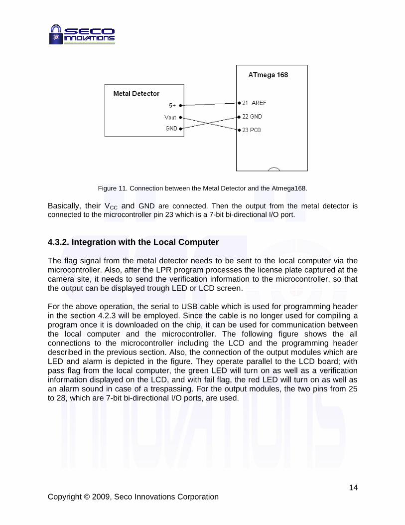
Figure 11. Connection between the Metal Detector and the Atmega168.
Basically, their VCC and GND are connected. Then the output from the metal detector is
connected to the microcontroller pin 23 which is a 7-bit bi-directional I/O port.
4.3.2. Integration with the Local Computer The flag signal from the metal detector needs to be sent to the local computer via the microcontroller. Also, after the LPR program processes the license plate captured at the camera site, it needs to send the verification information to the microcontroller, so that the output can be displayed trough LED or LCD screen. For the above operation, the serial to USB cable which is used for programming header in the section 4.2.3 will be employed. Since the cable is no longer used for compiling a program once it is downloaded on the chip, it can be used for communication between the local computer and the microcontroller. The following figure shows the all connections to the microcontroller including the LCD and the programming header described in the previous section. Also, the connection of the output modules which are LED and alarm is depicted in the figure. They operate parallel to the LCD board; with pass flag from the local computer, the green LED will turn on as well as a verification information displayed on the LCD, and with fail flag, the red LED will turn on as well as an alarm sound in case of a trespassing. For the output modules, the two pins from 25 to 28, which are 7-bit bi-directional I/O ports, are used.

15 Copyright © 2009, Seco Innovations Corporation
Figure 12. Realized circuit for the Microcontroller Module.

16 Copyright © 2009, Seco Innovations Corporation
5. License Plate Recognition (LPR) Module The role of License Plate Recognition (LPR) module parallels the role of brain in human body; it is a processing unit based on the inputs it receives. As a result, its accurate performance is the most important factor for the correctness of the overall system. The following figure shows the brief overview of the LPR system with the intermediate results.
Figure 12: System Block Diagram of LPR Module and Sub-Systems
The module is composed of a sequence of multiple sub-processes: image capture by camera module, localisation of license plate from captured image, skew correction, letter recognition, and verification. As each sub-system is highly dependent of its preceding module, the design requirements of them must be carefully followed during implementation of the system. In this part of the document, the design specifications of each module are presented and discussed in detail.
5.1. Camera Module The camera module acts as an eye of the system, and takes a snapshot of the approaching vehicle. Many design options for the camera module have been considered, including external webcams, built-in webcams and surveillance cameras. For the proof-of-concept system, a built-in HP Pavilion webcam from a laptop computer

17 Copyright © 2009, Seco Innovations Corporation
will be employed, which features 1.3 mega pixels and 640 x 320 resolutions. The choice for the camera module is at a very low standard, but its image quality is adequate enough to capture an image with a portion of license plate and to implement digital image processing for recognition. For this reason, a high quality camera is not needed for the prototype system. However, the final commercialised product will implement a high quality camera, which will be connected to the local computer via USB connection. The webcam will be triggered by the metal detector which detects a license plate or other extra metal that replaces an actual vehicle and then the captured image will be sent to the localization module for further image processing.
5.2. License Plate Localisation The camera captures an image of an approached vehicle as a whole frame. Thus, the localization of the license plate from the image is the first priority task and is the key step in LPR system. In order to detect the candidates of the license plate region, a morphological method will be used to distinguish the region as best as possible. The license plate, which consists of several characters, features a high contrast to its background as it must be easily recognised by the police or other authorities. An opening operation which combines the two morphological transformations of dilation and erosion can be used to blur the image. When the whole image is blurred, the spatial variation in the character region will be more frequent than any other regions in the image. Hence, subtracting the blurred image from the original image will produce an image with distinguishable character region and possibly other few regions with sharp edges and small areas which are removed at the opening operation. Due to the possible small areas with sharp edges from the original image, there will be a number of candidate regions in the subtracted image. To correctly choose the candidate region of the real license plate, a post processing of the image is needed to be carried out. First, the noise filter will reduce any noise caused by the image subtraction. Then the contour of vertical and horizontal projection of the image will be analyzed to correctly determine the license plate among the candidates. The high concentrated contours will likely to be the best candidate for the license plate because the character regions have more spatial variations than other particular regions. Using proper thresholds for vertical and horizontal projection, we can pick the four corners of the high concentrated area and finally localize the license plate region from the original image. Other methods of localizing the license plate from an image are also considered, which use different filtering process. However, the method described above will be employed, as its morphological operation is the most comprehensible from the developers’ point of view, and hence, it is the most familiar approach to develop the system. The following flowchart illustrates the operation of the module.

18 Copyright © 2009, Seco Innovations Corporation
Figure 13: System Block Diagram of License Plate Locator
5.3. Skew Correction The resulting image from the license plate localisation of the original image may be skewed by some angles, or in rhombus shape. To enhance the accuracy rate of the overall system, the deformed image must be reoriented as close as possible to a rectangular shape, if not perfectly rectangular, by the skew correction module. The algorithm for the module will be programmed in C++ computing language using OpenCV libraries. The module is a sequence of simple processes. The first process is detecting the upper, lower, and two vertical edges of the license plate using Canny edge detector. After finding the edges and their equation, the module computes the intersections of the edges to locate the four corners of the plate; the intersection of the upper edge and left vertical edge is the upper-left corner of the license plate, and so on. Using the four corners and pre-defined destination points, the module calculates the perspective transform matrix, using cvGetPerspectiveTransform function given in OpenCV library [4]. Then the image undergoes the perspective transform to correct the image skew, using transform matrix and cvWarpPerspective OpenCV function [4]. The de-skewed image will be saved on a local computer and the module will initiate letter recognition module. Perspective transform, or homographies, actually refers to a method for computing the resultant image of a plane in three-dimensional space as perceived by an observer, who may be looking at the plane at a certain angle, and by using the same technique, the
Subtract the blurred image from the original image
Perform vertical and horizontal projection
to the subtracted image
Pick the contours of high concentrated
region
Receive input image from the camera
module
Localize the plate from the original
image
Transfer the image into gray-scale
(.pgm)
Perform the opening operation to blur the
image

19 Copyright © 2009, Seco Innovations Corporation
reverse is also possible. Since the transform is in three-dimensional space, the transform matrix is 3-by-3. On the other hand, affine transform is in two-dimensional space and based on 2-by-3 matrix as it can be represented by matrix multiplication followed by a vector addition [4]. As both transforms require the calculation of their transform matrix, the perspective transform is used in the system to provide better quality image for the following processes. It must be noted, however, that the calculation of perspective transform matrix may take longer than the calculation of affine transform matrix. The pre-defined destination points are required for transform matrix calculation. The destination points are: (0, 0) for upper-left corner, (width, 0) for upper-right corner, (width, height) for lower-right corner, and (width, 0) for lower-left corner, where width represents the width of the image and height represents the height of the image. The following flowchart describes the image de-skewing process.
Figure 14: System Flowchart for Skew Correction Module
5.4. Letter Recognition After properly localizing the plate with any skews fixed, the character recognition will be performed by converting the license plate number to its corresponding ASCII characters. First, the characters need to be segmented so that each of them can be framed
Calculate coordinates of four
corners
Load pre-defined destination points
Calculate Transform
Matrix
Transform the image
Save the resulting image
Receive input image from the license
plate locator
Initiate letter recognition module
Detect four edges of license plate from the input image
Calculate equations for the edges

20 Copyright © 2009, Seco Innovations Corporation
individually and later matched with pre-defined templates. The vertical projection can be used to segment the characters. Using the projection contour, which will have high positive values for the characters and very low positive values for the intervals, the module detects the white spaces between each character. The distance between the two intervals will represent the width of each character and segmentation of the characters can be achieved by cropping the image. The vertical projection contours for each segment can be used to identify each character. The vertical projection contour templates for all possible characters (A~Z and 0~9) will be pre-defined so that a character can be identified by matching. The each segmented characters need to be resized to be in same dimension as the templates for proper matching. Then the each character from the license plate will be matched with the templates in the order. As some of the characters with similar vertical contours, including 0 and 8, 3 and 9, 5 and 6, can result confusion and error, a post-process using horizontal projection will be implemented to ensure the accuracy of the system.
Figure 15: System Flowchart for Letter Recognition
Perform horizontal projection for 0, 3, 5,
6, 8, 9 in which vertical projection can be confused
Receive license plate image from the localization module
Identify each character by converting to
corresponding ASCII character
Perform vertical projection on the
image
Segment each character by low positive values of
the projection contour
Perform template matching for each
character using high positive values

21 Copyright © 2009, Seco Innovations Corporation
5.5. Verification Module As the last stage of the LPR system, the verification module will search for the recognised letter string in the database. As mentioned above, for the proof-of-concept system, an unsorted list of license numbers will replace the database unit, and the verification module will check for the specified string by sequential search. The module sends pass signal to communication module in the microcontroller unit if the letter string is found in the list, and sends fail signal if not found. The following flowchart illustrates the operation of the module.
Figure 16: System Flowchart for Verification Module
Due to the inefficiency of the database unit and the search algorithm of the module, the overall system will suffer from the undesirable delay. Alternatively, the list of the registered vehicle can be sorted by alphabetical order before searching and more efficient search algorithm, such as binary search or interpolation search, can be implemented to improve the operation time of the module. Furthermore, the database can be structured in a tree or hash table to provide much efficient search method. However, due to the time and budget constraints, the database will be replaced by an unsorted list and searched using sequential search algorithm.
Search database
Is Found?
Receive recognised letter string
Send pass signal to
microcontroller
Send fail signal to
microcontroller

22 Copyright © 2009, Seco Innovations Corporation
6. System Test Plan The unit test of each individual modules and the integration test of the overall proof-of-concept system will be performed to ensure all requirements are satisfied. The integration test will be completed after each module has met their software and hardware specification. In this section of the document, the description of the test plans on individual modules as well as on the overall prototype of the system will be proposed.
6.1. Hardware Testing To achieve an error-free system, the sub-circuits of the metal detector will be tested thoroughly before the integration testing is performed. The main focus of the unit test plan is to verify if each sub-circuit and the overall circuit operate properly. The modification of circuit design and the replacement on the values of electronics may be required during the integration process, based on the result of the unit testing. Upon the acquisition of the accurate sub-systems, the integrated circuit will be tested using metallic object in various sizes and shapes to collect their different voltage levels. The collected data will be used for setting the threshold value for the interrupt signal. To test the microcontroller module, a simple testing program will be programmed. The program sends a random sequence of verification information signal and checks if the signal is accurately processed to operate the corresponding outputs modules of the LED and the alarm. The expected transition time for one-way system flow from the testing PC to output modules is less than one second. The purpose of this testing is to verify the chip operates within the expected time frame with minimum number of error, and to ensure the error-free control algorithm and accurate communication with the local computer. Based on the test results, the program on the chip may be modified to enhance the system accuracy.
6.2. License Plate Recognition Module Testing The LPR module is the key component of the overall system, and hence, the correctness of the module is the most important factor determining the successful operation of the system. As sub-module of the LPR system is interdependent of each other, each module will be tested thoroughly before integration. LPR integration test will also be performed to ensure the correctness and the accuracy of the system.
6.2.1. Camera Module Testing The built in webcam from our main computer will be triggered by the metal detector. The two modules communicates through microcontroller board thus, the camera needs to receive a signal properly whenever the metal detector detects metal that is assumed to

23 Copyright © 2009, Seco Innovations Corporation
be a vehicle with license plate. Then the camera will capture the image of the license plate and save image to the computer for digital image processing. The test scenario is describes as follows:
1. The license plate is placed on the metal detector and can be viewed from the webcam.
2. The metal detector sends a signal through microcontroller board to the computer.
3. The webcam captures an image of the license plate. 4. The image is saved to the computer for license plate recognition module.
6.2.2. License Plate Localisation Testing The license plate localization is the key step in the whole system and the proper localization is needed as there will be a number of license plate candidates from the captured image. Thus, in order to ensure that the proper candidate is chosen, the testing needs to be carried to achieve 100% accuracy. The key method used for the localization is opening operation which produces blurred image. The image must be blurred enough so that the characters in the plate have the most spatial variation. Then, from the subtraction and noise filtering process, the characters will be left out very much compare to other regions. The test scenario is describes as the following:
1. The opening operation is performed on the captured image. 2. The characters in the plate are sufficiently blurred. 3. The subtracted image is filtered for noise elimination. 4. The vertical and horizontal projection is performed. 5. The character region can be distinguished from the projection contour
6.2.3. Skew Correction Testing Upon receiving the localised image of license plate from the preceding license plate localisation module, skew correction module detects the four corners of the license plate from the image, and adjusts the image to the close-to-perfect rectangular shape by remapping the corners into the defined destination point. Correct and accurate adjustment by skew correction module is the highly important in the LPR module, and thus in the product to produce correct output, as letter recognition module assumes rectangular image for its process. To test the correctness of the output, a simple test script will be programmed. The test scenario is described below:
1. A skewed image of a license plate is loaded by the module. 2. The module makes adjustments to the deformation of the image, and save the
adjusted image to the local computer.

24 Copyright © 2009, Seco Innovations Corporation
3. Perform the skew correction algorithm on the deskewed image once more, and compare two resulting images by image subtraction.
4. The module is said to be correctly performing its task if and only if the two images are matched within the accuracy of 1%.
6.2.4. Letter Recognition Testing The letter recognition testing will be carried with all possible characters in the license plate, which are A to Z and 0 to 9. To produce the projection contour templates for matching, the characters from the real license plate will be needed so the number of license plate images will be collected to gather all the characters and produce the templates using vertical projection. Then the test will be carried with number of license plates that contain all the possible characters. The template matching for each character will be performed with pre –defined character templates and test will be carried to see if the identification is correct within accuracy of 1%. The following list describes the testing scenario:
1. Perform vertical projection on the localized license plate image. 2. Segment each character by the low positive values which represent the intervals. 3. Using the projection contour of each character, match it with pre-defined
templates for identification. 4. Test with all possible characters; especially for 0, 3, 5, 6, 8, 9, and see if the
accuracy is within 1%.
6.2.5. LPR Integration Testing After integrating the individual modules for LPR system, LPR integration testing will be performed to ensure the LPR system properly operates without an error. As the LPR system acts as a brain of the whole system, the accurate performance of LPR system is the key requirement of the product. The test scenario is presented below: 1. An image of a vehicle, with its license plate showing, is loaded by the module. 2. The module processes the image digitally, saving the result images of each step. 3. After the module performs all the steps, the recognised letters are recorded on the
local computer. 4. Verifies whether the letters are correctly recognised from the original image. If
necessary, check the images from each step. 5. The integration test will be performed for at least few tens of times for checking
performance accuracy. 6. The LPR system must have at least 95% of accuracy.

25 Copyright © 2009, Seco Innovations Corporation
6.3. Integration Testing The integration testing for the whole system will be followed after successfully passing all the unit tests for each module. Once the each module testing is completed, the integration testing will be really a matter of proper digital communication between the modules. The metal detector, LPR algorithm, and microcontroller with output display will be integrated successfully by verifying the communication such that the system can play a role as the LPR auto-gate system which controls parking lot access. The test scenario is presented below:
1. All the modules are properly connected through com port and USB. 2. The license plate, which, as its own, imitates a vehicle, is approached at the
camera and stopped upon the metal detector. 3. The camera captures the image of the license plate. 4. The LPR software runs. 5. The registration status of the vehicle is displayed though LED and the number is
displayed on the LCD. 6. If the LED is on,
A. and if unregistered license plate is approached, the red LED turns on, and the alarm sounds if the license plate passes the entrance gate.
B. If a registered license plate is approached, green LED turns on, or remain on for another few seconds.
7. If the LED is off, A. and if an unregistered license plate is approached, the red LED turns on. B. If a registered license plate is approached, the green LED turns on.
The above test scenario will be performed number of times to ensure that the communication between the modules is within the accuracy of 1%.

26 Copyright © 2009, Seco Innovations Corporation
7. Conclusion This document describes the design specification for a LPR Auto-gate System to ensure that the functional requirements of the system are met. The design choices for metal detector, microcontroller, and LPR system are also discussed in the document. By meeting all the specifications, the product will provide a more secure and convenient solution to building residents and management. The proof-of-concept system is well under its development progress, and is targeted to be completed by the date of April 14th, 2009. If the product is to be taken to the market, the final product will be commercialised in one year from the prototype production date.

27 Copyright © 2009, Seco Innovations Corporation
8. References [1] Seco Innovations Corporation. February 2009. Functional Specification for a
License Plate Recognition (LPR) Auto-gate System. Simon Fraser University, Burnaby, BC, Canada
[2] Total Phase Inc. 2008. Knowledge Base – Article 10048: USB vs. Serial and Parallel. http://www.totalphase.com/support/kb/10048/ [Accessed: February 22nd, 2009]
[3] G. Baridski and A. Kaehler. 2008. Learning OpenCV: Computer Vision with the OpenCV Library. O’Reilly Media Inc. Sebastopol, CA, US
[4] John F. Canny. 1986. A Computational Approach to Edge Detection. IEEE Transactions on Pattern Analysis and Machine Intelligence 8.
[5] C.R. Nave. 2005. The Schmitt Trigger. Hyper Physics. http://hyperphysics.phy-astr.gsu.edu/Hbase/Electronic/schmitt.html [Accessed: February 25th, 2009]
[6] Peter Ouwehand. 2006. How to Control a HD44780-Based Character-LCD. http://home.iae.nl/users/pouweha/lcd/lcd0.shtml#pin_assignment [Accessed: February 25th, 2009]
[7] Atmel Corporation. 2009. Datasheet for ATmega168. San Hose, CA, US. http://www.atmel.com/dyn/products/product_card.asp?part_id=3303 [Accessed: February 28th, 2009]
[8] C. WU, L. C. ON, C. H. WENG, T. S. KUAN, K. NG. August 2005. A Macao License Plate Recognition System, Faculty of Information Technology, Macao University of Science and Technology. Macao, China.
[9] Korea Electronics Ltd. December 1998. KIA7805AP Semiconductor Technical Data. Korea.
[10] Zilog Inc. Z86E43/743/E44 CMOS Z8® OTP Microcontrollers. Campbell, CA, US. http://www.datasheetarchive.com/Z86E3416VSC-datasheet.html [Accessed: February 28th, 2009]

a Copyright © 2009, Seco Innovations Corporation
Appendix A – Derivation for Hardware Component Values
A.1. Band-Pass Filter The schematic of the band-pass filter is shown below.
Figure A1 : Band-Pass Filter
Writing the node equations at the inverting input of the op-amp and at the junction where R1, R3, C1, and C2 join, we have,
0)( 12
31
sCVVsCVR
V
R
VVoutaa
aina , and (A1)
02
2 R
VsCV out
a . (A2)
Solving the two equations, the transfer function of the circuit is given by:
21321
31
212
212
11
)(
)1
(
CCRRR
RR
CCR
CCss
CRs
V
V
in
out
(A3)
Equating this with the standard band-pass filter equation, 22
n
nin
out
sQ
s
s
V
V
, we have
the following relationships:
21321
31
CCRRR
RRn
, (A4)

b Copyright © 2009, Seco Innovations Corporation
)()(
211
22
CCR
CRQA
n
n
, and (A5)
)(212
21
CCR
CC
QBandwidth n
, (A6)
where ωn is the centre frequency, and A(ωn) is the gain at the centre frequency. Letting ωn equals to 60 Hz and the bandwidth to 10 Hz, the values for the component can be easily calculated.
A.2. Differentiator The differentiator used in the metal detector is realised as the following circuit diagram.
Figure A2: Differentiator
From the above figure, we can easily write the transfer function relating the input signal and the output signal. Assuming ideal op-amp, the transfer function of the differentiator is:
11)(
)(
1
2
1
2
CsR
CsR
sCR
R
sV
sV
in
out . (A7)
From the equation, we can easily conclude that the differentiator also acts as a high-
pass filter as it has one zero at origin and one pole at CR1
1. The high frequency gain is:
1
2)(R
RAv . (A8)
and the cut-off frequency is approximately:

c Copyright © 2009, Seco Innovations Corporation
CRc
1
1 . (A9)
By setting the appropriate values for the cutoff frequency ωc and the gain, the component values can easily be calculated.


![Vehicle License Plate Detection: A Surveylicense plate using image processing technologies [17]. LPR is used in various traffic applications, such as dynamic traffic control emergency](https://img.dokumen.tips/doc/110x75/5ec7d115cc408c7a5355965e/vehicle-license-plate-detection-a-survey-license-plate-using-image-processing-technologies.jpg)