Embed Size (px)
Citation preview

DESIGN SELECTION OF A WIND TURBINE BLADE USING PREPREG MATERIALS
C. Monroy Aceves*1, M.P.F. Sutcliffe1, M.F. Ashby1, A.A. Skordos2, C. Rodríguez Román3
1 Cambridge University Engineering Department Trumpington Street, Cambridge, CB2 1PZ, UK.
* [email protected] 2 Composites Centre, Cranfield University, MK43 0AL, UK
3 Instituto Politécnico Nacional, ESIME Ticomán Av. San José Ticomán 600, México D.F. C.P. 07340, México.
SUMMARY A design selection methodology is used to select an optimum composite wind turbine blade given the aerodynamic and centrifugal loading. An exhaustive search of a wide range of possible design blade solutions is made. The analysis is done using the finite element method. The results are explored using a material selection software.
Keywords: Design, composite selection, structural analysis, optimisation, wind turbine blade
INTRODUCTION A wind turbine is being developed, in collaboration with the Instituto Politécnico Nacional (IPN), Mexico, to provide electricity in houses in rural areas. The IPN has built a prototype which has been tested in a location near Mexico City. This prototype is taken as a benchmark and a new blade is being developed to optimise aerodynamic performance. The prototype blade was made of GFRP using a hand-layup process. Hence the quality was low and the repeatability of the blade properties could not be easily controlled. The weight of the prototype blades varied from 2 to 2.5 kg, and the thickness of the blade was not constant. The mechanical properties of the blade are not very accurate, suggesting that it could be improved. The aim of this paper is to find the best composite blade solution, in terms of material, thickness, reinforcement and layup, that satisfies the constraints of the design while reducing the weight of the blade.
The design strategy for the blade considers aerodynamic loading, assessed via computational fluid dynamics, and variable structural properties including prepreg material, the thickness and layup of the blade’s shell and the thickness and extent of unidirectional material used as a spar. Selection of an optimum design follows the methodology described in [1].

AERODYNAMICS
In a wind turbine, the right balance between the lift and drag generated by the blades drives the fan [2]. For a constant incident wind speed, V0, the relative wind speed and direction change from the root to the tip of the blade because of the rotational velocity. Thus the geometry (or the airfoil sections) should change along the blade to optimise the aerodynamic design.
The airfoils closer to the tip of the blade generate higher lift due to the speed variation in the relative wind, while the duty of the airfoils at the root of blade is mainly structural, contributing to the aerodynamic performance of the blade but at a lower level. Thus the root of the blade is bigger and stronger than its tip. This is shown in Fig. 1, where two airfoil sections are shown. Figure 1(a) shows an airfoil at the root of the blade, while Fig. 1(b) shows the airfoil located at 75% along the length of the blade.
For aerodynamic design, the blade was divided into 25 sections (or stations) and the geometry and angle of the airfoil in each station was obtained. Station 1 is the root of the blade while Station 25 is the tip of the blade. The geometry of each airfoil was designed using a parametric technique called PARSEC [3]. The pitch angle for each airfoil was calculated in order to secure a constant angle of attack throughout the blade of 7º, assuming the working conditions of an incident wind speed V0 = 8 m/s, an angle of attack α = 7° and an angular velocity ω = 400 rpm.
Once the geometry was established, each station was analysed using the computational fluid dynamics (CFD) software package FLUENT [4] to obtain the pressure distributions along each airfoil section. An example of the results obtained is shown in Fig. 1. Note that the airfoil in Fig. 1(b) has a negative pressure (responsible for the lift) 28 times greater than the airfoil in Fig. 1(a).The pressure distributions calculated are used later for the structural analysis of the blade.
(a) (b)
Figure 1. Pressure profiles calculated with CFD for each of the 25 sections of the blade. The pressure profiles for two airfoil section are shown; a) Station 2 near the root of the blade and b) Station 22 at 75% of the length of the blade. Note the different scales; the
pressures in Station 22 are around 25 times bigger than those in Station 2

DESIGN METHOD
Definition of the problem
The objective of the case study is to design a low air speed wind turbine blade, so as to reduce the weight of the blades, comparing the final design with the existing prototype. Details of the operating conditions are as specified in the proceeding section. The fan of the wind turbine has a diameter of 3 m.
Geometry and loading
A sketch of the blade is shown in Fig. 2. The wind turbine rotates around the Z axis in the X-Y plane. The structural analysis of the blade considers the centrifugal forces and the aerodynamic load. For bigger wind turbines (e.g. with fan diameters over 40 m), the self-weight of each blade would also need to be considered [5].
The aerodynamic load applied was calculated using the pressure distributions obtained with the CFD analysis. The geometry of each airfoil section was discretised using 40 points, which were used to create the finite element model. Thus only 40 values for the pressure were needed. A curve was fitted to the pressure distribution found with FLUENT, and values interpolated as needed.
The incident wind is considered to have a direction in the negative Z direction. It is expected that the loading causes a twist of the blade around the Y axis, while the tip bends in the X and Z directions. Due to the centrifugal loading the tip of the blade will deflect in the Y axis. This deflection is neglected however, as it will not change the aerodynamics of the blade nor endanger the structure. The coordinates of two points labelled 'A' in Fig. 2, located at the leading and trailing edge of Section 25 of the blade, are recorded before and after applying the loads and used to calculate the displacement and twist of the blade.
Figure 2. Geometry and loading sketch.

Shell and Reinforcements
The blades are assumed to be made of two parts: a shell and reinforcement. The shell follows the geometry set by the airfoil sections and it provides the aerodynamic surface. The torsional stiffness of the blade is due to the shell, while the bending stiffness due to the reinforcement. The use of these two parts sets the challenges of: (i) finding the right balance of shell and reinforcement, (ii) specifying the amount of reinforcement and (iii) identifying the location and shape of the reinforcement. The details of the variables involved with the shell and reinforcement are described as follows.
Shell
The shell of the blade is assumed to be a constant layup (and thickness) throughout the entire blade to simplify manufacture. Thus the maximum thickness of the blade is restricted by the size of the airfoil at the tip of the blade. The maximum shell thickness is limited to the thickness of the trailing edge of this airfoil. This limiting condition is illustrated in Fig. 3 where the sizes of two airfoils are compared, one near the root of the blade and the other at the tip of the blade. The small size of the airfoil at the tip of the blade limits the amount of material that can be used if a constant thickness throughout the blade is desired.
Six shell layups and thicknesses were chosen. Table 1 shows the six layups allowed for the shell. The layups selected are those that can be made out of a maximum of 16 plies, being balanced and symmetric, and using only ± 45° plies plus a maximum of 20% of 0° plies. These layups are selected to help with the rotational stiffness of the blade.
Figure 3. Thickness lower limit.
Table 1. Shell layup.
Case Layup Plies Thickness (mm)
1 [±452]s 8 1 2 [±453]s 12 1.5 3 [±454]s 16 2 4 [±45/ 0 ]s 9 1.125 5 [±45/0/±45]s 10 1.25 6 [±45/0/±45/ 0 ]s 11 1.375
Reinforcements
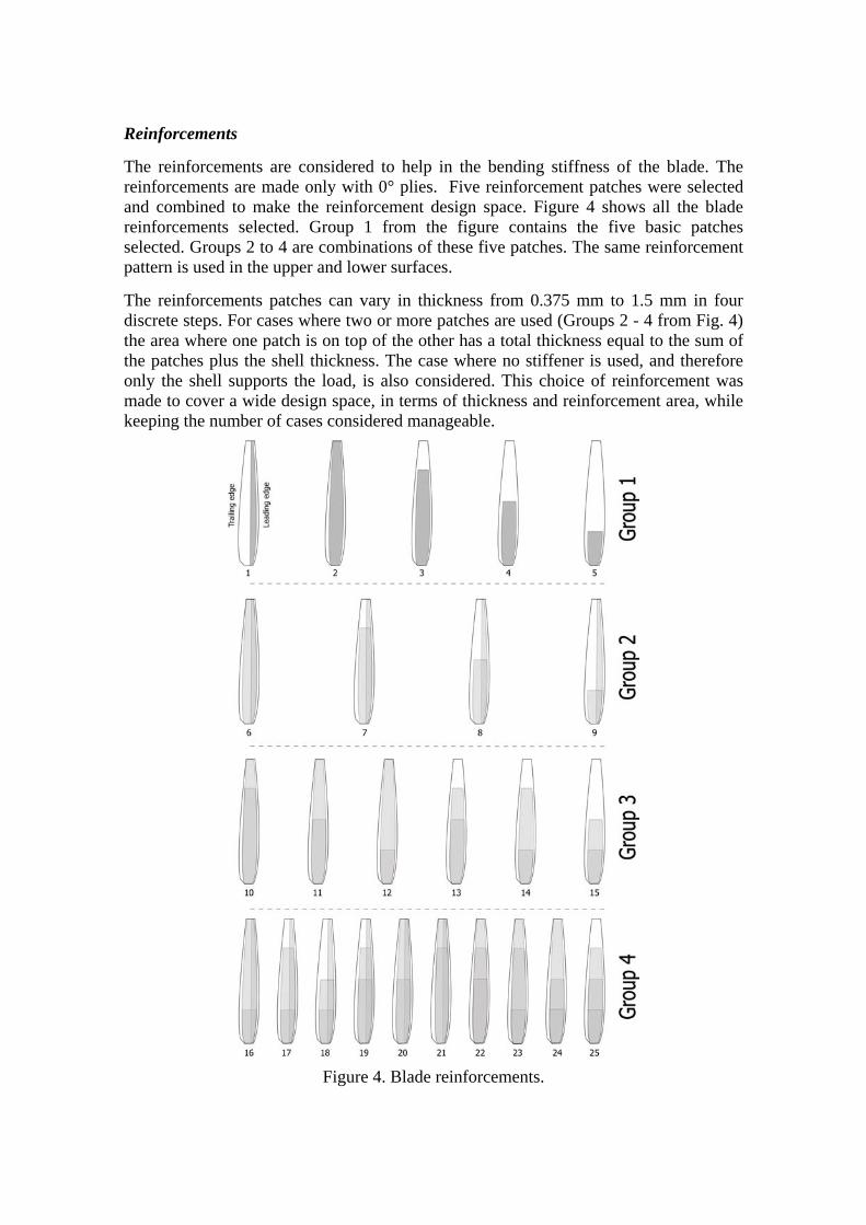
The reinforcements are considered to help in the bending stiffness of the blade. The reinforcements are made only with 0° plies. Five reinforcement patches were selected and combined to make the reinforcement design space. Figure 4 shows all the blade reinforcements selected. Group 1 from the figure contains the five basic patches selected. Groups 2 to 4 are combinations of these five patches. The same reinforcement pattern is used in the upper and lower surfaces.
The reinforcements patches can vary in thickness from 0.375 mm to 1.5 mm in four discrete steps. For cases where two or more patches are used (Groups 2 - 4 from Fig. 4) the area where one patch is on top of the other has a total thickness equal to the sum of the patches plus the shell thickness. The case where no stiffener is used, and therefore only the shell supports the load, is also considered. This choice of reinforcement was made to cover a wide design space, in terms of thickness and reinforcement area, while keeping the number of cases considered manageable.
Figure 4. Blade reinforcements.

Materials
The materials chosen are glass and carbon fibre reinforced polymers prepregs, using material properties taken from [6]. Approximate costs of 5 and 100 £/kg have been used for the GFRP and CFRP, respectively. The ply thickness available for both materials is assumed to be 0.125 mm. In principal the shell of the blade and the blade reinforcements can be either glass fibre or carbon fibre composite. In fact the case of CFRP shell plus GFRP reinforcement is not considered, to give the three possible combinations shown in Table 2.
Table 2. Material combinations.
Case Shell Reinforcement
1 Carbon fibre Carbon fibre 2 Glass fibre Carbon fibre 3 Glass fibre Glass fibre
Structural analysis
The finite element model used for the structural analysis consists of 1000 shell elements (25 sections of 40 elements each). The XYZ coordinates of the 25 stations are used to create the finite element model of the blade. Each airfoil is divided into 40 nodes. The nodes of two consecutive airfoils are used to create the elements. The loads applied are the aerodynamic forces and the centrifugal force due to the rotation of the wind turbine. The principal direction of the fibres (i.e. the 0º orientation) is parallel to the long axis of the elements. The blade is considered to be clamped at the root. The analysis was done using MSC.Marc [7]. Each analysis run takes around 60 seconds to complete.
The results obtained from the FE analysis are the coordinates of the trailing and leading edge of Station 25 after deformation and the Failure Index, considering a first-ply-failure criterion and a Hoffman criterion. The coordinates were used to calculate the twist and deflection of the blade.
Design objective
The design objective is to minimise the mass. The geometry of the blade was defined by the Instituto Politécnico Nacional, fixing the airfoil sections. Three combinations of materials are considered, 1) using GFRP only, 2) combining GFRP for the shell and CFRP for the reinforcements, and 3) shell and reinforcement of CFRP. The shell can have six layups. The reinforcements all have only 0° plies and can take 4 discrete thicknesses. In total 25 reinforcement cases are considered (plus the case where no reinforcement is used). The design space consists of 14,778 different blades. All of these cases were analysed following the method described in [1].
The design constraints, variables and objectives for this case study are summarised in Table 3. The bending stiffness constraint is set to avoid the blades hitting the structure that holds the wind turbine. The twist of the blade (or torsional stiffness) is constrained to guarantee a good aerodynamic performance. A database with all these result was built in and then imported into a material selection software, CES [8], as described in [1].

Table 3. Constraints, variables and design objectives for a wind turbine blade.
Constraints
Geometric: Fixed geometry. Loading: Aerodynamic pressure and centrifugal loading. Stiffness: The deflection at the tip of the blade should not exceed 20% of the blade length. The blade tip should twist less than 3.5 degrees. Failure: The blade should not fail under the loads applied.
Variables
Shell thickness. Shell layup. Reinforcement combination. Reinforcement thickness. Material combination.
Objective To minimise weight.
RESULTS The results for the 14,778 cases are shown in Fig. 5. The mass of the blade and the Failure Index are shown in Fig. 5(a). Figure 5(b) plots the bending in both axes, while the twisting of the blade is shown in Fig. 5(c).
From Fig. 5(a) it can be seen that the strongest blades are those made completely of carbon fibre (shown in red), the second strongest is the group that combines a glass fibre shell with a carbon fibre reinforcement (blue) and the weakest group uses only glass fibre (green). For the loading conditions considered failure of the laminate is due to the centrifugal loading. The aerodynamic pressure is not enough to break the blade.
Figure 5(b) shows that the stiffer blades (at the top right corner) are the carbon blades, while the more compliant blades are made of GFRP. Even for the worst blade the deflection in either axis is no more than 5 cm, which means that all the blades satisfy the stiffness criterion. It may thus be concluded that bending is irrelevant in this design. The blade will not hit the tower when in operation.
The twist of the blade is plotted in Fig. 5(c). It can be seen that the blade twist is in the range of 2.4 to 6 degrees. The CFRP blades twist less than the others, being all grouped on the top right part of the graph. The GFRP and glass-carbon blades have similar twist ranges. This is because the rotation of the blade is mainly controlled by the shell. Thus, as both groups have the same material shell, they have roughly the same twist range.

Figure 5. Blade results.
Selection In order to select an optimum blade, the design choices are plotted using the material selection software [8], and design constraints are applied, following the method described in [1]. This selection is illustrated in Figs. 6(a) and 6(b), where the strength and maximum rotation constraints are applied. The bending stiffness criterion is not relevant as all the designs satisfy this constraint. In these figures the designs that do not satisfy both of the constraints are greyed out.
After applying these constraints, we still have over 4,500 possible designs, most of them being CFRP blades. Some of the glass-carbon blades satisfy the criteria, but they are heavier than most of the CFRP designs. All the blades made entirely of GFRP fail the strength criterion. To use an entirely glass fibre blade a different shell, reinforcement or manufacturing method would have to be used (as in the case of the prototype).
At this stage the formal design objective of minimising mass can be used to identify the lightest design which meets the design constraints. This is identified as case A in Fig. 6(c), which is a CFRP blade. Details of the design are given in Table 4. A refinement of the selection would, however, consider further the trade-off between mass and cost, considering that a heavier but cheaper GFRP blade may be preferable to the lightest CFRP blade.
The trade-off curve of material cost as a function of blade mass is plotted in Fig. 6(c). Here we simply calculate the blade cost as the cost of the material, so that cost and weight are linearly related for a given material. A more accurate cost model could be used to find the final cost of the blade. Two points have been identified in Fig. 6(c), that lie on the trade-off surface. Point A is a CFRP blade and Point A1 is a blade combining
(c)
(a) (b)

glass and carbon fibres. The properties of these two points are shown in Table 4. It is possible to select either of these two points, acknowledging that we cannot minimise the weight without increasing the cost. To choose between these designs a penalty function needs to be established to quantify the trade-off between cost and mass. After considering the entire design – the blades, hub, gearbox, generator, nacelle and tower – there is likely to be a significant penalty in choosing a cheaper but heavier blade.
Taking this into account, Point A is likely to be the best option. However, the flexibility of the method makes it easy to consider changes in the constraints. For example, using the prototype as a benchmark, we can apply the constraint that the maximum weight allowed for the blade is 2 kg and, in order to guarantee the blade aerodynamic performance, a maximum rotation of ± 3º is applied. Points A and A1 no longer satisfy these tighter constraints and the best blade is now Point B, which is shown in Figs. 6(c) and 7 with the properties shown in Table 4.
Figure 6. Blade selection.
Table 4. Blade results; Points A, A1 and B.
Point Shell layup Shell material
Reinf. Case
Reinforcement thickness (mm)
Twist (º)
Mass (kg)
Cost (£)
A [±452]s CFRP 1 Patch 1 = 0.375 -3.08 0.924 92
A1 [±454]s GFRP 8 Patch 1 = 1.500 Patch 4 = 0.375 -3.23 2.439 55
B [±45/0/±45/0]s CFRP 0 - -2.98 1.15 115

Figure 7. Blade final selection.
CONCLUSIONS This paper has applied the composite design method presented in [1] to a real case study. The proposed solution satisfies the design requirements and improves on the benchmark by reducing the weight by almost 50%. The design solution can be further analysed and improved in later stages of the design process, where a more accurate FE analysis, cost model and coupling with the entire structure is carried out.
The method presented has helped to visualise and quantify the interplay of the multiple variables and constraints in the design.
The complexity of this case study confirms that the method presented here is suitable for real design situations. It helps the designer to make decisions in the early stages of the design process. Even for an experienced composite designer, the complexity of the case study presented in this paper would present a significant challenge in selecting a priori a combination of layup, material, thickness and configuration with confidence. The final result could not easily be predicted.
References 1. C. Monroy Aceves, A. A. Skordos, and M. P. F. Sutcliffe. Design Selection
methodology for composite structures. Materials and Design, 29:418–426, 2008.
2. M. O. L. Hansen. Aerodynamics of Wind Turbines. James & James Ltd., 2003.
3. H. Sobieczky. Parametric airfoils wings. In K. Fujii and G. S. Dulikravich, editors, Notes on Numerical Fluid Mechanics, volume 68, 71-88. Vieweg Verlag. 1998.
4. ANSYS Inc. FLUENT. www.fluent.com/software/fluent/index.htm
5. P. Brøndsted, H. Lilholt, and A. Lystrup. Composite materials for wind power turbine blades. Annual Review of Materials Research, 35:167–207, 2005
6. R. F. Gibson. Principles of Composite Material Mechanics. McGraw-Hill, USA, 1994
7. MSC.Software Corporation. MSC.Marc. www.mscsoftware.com
8. Granta Design Limited. Cambridge Engineering Selector CES Edupack 2007. Cambridge, UK, 2007. www.granta.co.uk