Embed Size (px)
Citation preview

Design Rule Hierarchies and Parallelism in Software Development Tasks
Sunny Wong, Yuanfang Cai, Giuseppe Valetto, Georgi Simeonov, and Kanwarpreet Sethi
Department of Computer Science
Drexel University
Philadelphia, PA, USA
{sunny, yfcai, valetto, ges37, kss33}@cs.drexel.edu
Abstract—As software projects continue to grow in scale,being able to maximize the work that developers can carry outin parallel as a set of concurrent development tasks, withoutincurring excessive coordination overhead, becomes increas-ingly important. Prevailing design models, however, are notexplicitly conceived to suggest how development tasks on thesoftware modules they describe can be effectively parallelized.In this paper, we present a design rule hierarchy based on theassumption relations among design decisions. Software moduleslocated within the same layer of the hierarchy suggest indepen-dent, hence parallelizable, tasks. Dependencies between layersor within a module suggest the need for coordination duringconcurrent work. We evaluate our approach by investigatingthe source code and mailing list of Apache Ant. We observethat technical communication between developers working ondifferent modules within the same hierarchy layer, as predicted,is significantly less than communication between developers
working across layers.
Keywords-software architecture; collaboration; project man-agement
I. INTRODUCTION
In today’s large-scale, distributed software development
projects, it is increasingly crucial to maximize the level
of concurrency among development tasks, and at the same
time avoid incurring huge coordination overheads among
development teams tasked with concurrent work.
It has been long recognized that software modulariza-
tion plays a critical role in streamlining project coordi-
nation, as the need for coordination among developers is
closely related to the dependencies between the system
modules [1], [2]. Numerous researchers have explored the
interplay of coordination—in particular in the form of per-
sonal communication—and modularization for large-scale
software systems [3]–[7]. Still, prevailing models of design,
such as UML, are not equipped with formal means to
provide software project managers with explicit guidance
on how development tasks can be constructed, partitioned,
and assigned to maximize the parallelization of developers’
work, based on the dependency relations among the software
modules they describe.
Parnas’s information hiding principle [1] and Baldwin and
Clark’s design rule theory [8] provide key (although non-
operational) insights about the relation between software
modularization and task assignment. Parnas defined a mod-
ule as am independent task assignment, a concept that is
not equivalent to the conventional understanding of mod-
ules as structural constructs, such as functions or classes.
Baldwin and Clark define design rules as stable decisions
that decouple otherwise coupled decisions. Example design
rules include abstract interfaces, application programming
interfaces (APIs), etc. The more subordinate decisions that
depend on a design rule, the more influential it is, and the
more important it is to keep it stable. Identifying design rules
and their impact scopes is not trivial in large-scale systems.
In this paper, we present an approach to automatically
cluster a software dependency structure into a design rule
hierarchy (DRH) that manifests Parnas’s and Baldwin and
Clark’s definition of module and design rule. In this hier-
archy, the decisions within the top layer of the hierarchy
are the most influential design rules, which dominate the
rest of the system, and need to be kept stable. The deci-
sions within subsequent layers assume design decisions in
previous layers. The design decisions within each layer are
clustered into modules. Since modules within the same layer
are independent from each other, they become candidates for
concurrent implementation.
We hypothesize that this hierarchy, populated with suffi-
cient dependency relations, can shed light on the interplay
between software structure, task parallelism, and develop-
ers’ coordination needs. Concretely, the DRH predicts that
developers working on different modules within the same
layer do not have communication requirements [3]; whereas
dependencies between modules located in different layers, or
within the same module, create communication requirements
among developers working in those contexts.
The accuracy of the DRH predictions on coordination
requirements fundamentally depends on the quality of the
underlying model of software dependency. Cataldo et al. [9]
show that, for instance, syntactical dependencies extracted
from source code are not as effective as semantic rela-
tionships in terms of individuating coordination require-
ments. We recently developed an approach to precisely
define and automatically derive pair-wise dependency rela-
tions (PWDR) from a formal model called the augmented
constraint network (ACN) [10], [11]. An ACN expresses

design decisions as variables, models how those decisions
make assumptions about each other using logical constraints,
and complements the constraint network with a dominance
relation that formalizes the concept of design rules.
In this paper, we use the pair-wise dependency relation
(PWDR) derived from an ACN as the basis to form the
design rule hierarchy. Its efficiency will be discussed in the
evaluation section. The PWDR can be used to automatically
derive a design structure matrix (DSM) [8] with rigorous
semantics [10]–[12]. We developed a tool, called Minos1—
a refactored version of Cai’s Simon [10], [11] prototype
tool, to support ACN modeling and a number of modularity
analyses, including automatic DSM derivation.
We evaluate the effectiveness of the design rule hierarchy,
in terms of predicting parallel task assignments and mani-
festing the impact scope of design rules, by postulating the
following hypotheses: first, developers working on different
modules within the same DRH layer engage in technical
communication substantially less than other groups of de-
velopers. Second, on the contrary, the need for technical
communication is particularly strong for those developers
that work on modules that have cross-layer dependencies.
Third, the position of a design rule in the hierarchy reflects
its importance in the system, with the decisions at the top
level being the most influential on the overall system design.
To test the first two hypotheses, and since we did not have
an opportunity to study an ongoing project, and predict the
flow of “live” technical communication among developers,
we organized our evaluation around the mining of publicly
available archives and repositories of an open source project,
Apache Ant2 version 1.6.5. We reverse engineered its source
code into a UML class diagram and transformed the UML
model into an ACN [13], from which a DRH was derived
to predict coordination structure. It is worth noting that
although the ACN was indirectly transformed from source
code, the number of dependencies derived from the ACN is
much larger than the number of dependency pairs directly
discovered from source code using a reverse engineering
tool such as Lattix [14]. We derived 12,596 dependencies
from the Apache Ant ACN, while Lattix only shows 1,700
dependencies from the compiled binaries. The differences
are caused by indirect and implicit dependencies picked
up by the constraint network. Furthermore, we mined the
developers’ mailing list and the version control repository
of the project during the period leading to the following
release, 1.7.0, to infer concurrent development tasks and
related communications between developers.
Through statistical analysis, the first two hypotheses are
shown to be true: developers working on different modules
within the same layer of the DRH communicate significantly
less than other groups; and, the majority of interpersonal
1http://rise.cs.drexel.edu/wiki/Minos2http://ant.apache.org
communications happens instead between developers work-
ing on dependent modules located in different layers.
To test the third hypothesis, we similarly automatically
generated a DRH for Minos itself. Since we have developed
Minos, we can easily determine whether the hierarchy
reveals correctly the importance of its design rules. Again,
our hypothesis is supported; for example, the top layer of
the Minos DRH contains the most influential decisions of
the system.
In the rest of the paper we illustrate our method and
our experiments as follows: Section II introduces the back-
ground of this work. Section III illustrates our clustering
approach with a small example. Section IV presents the
DR hierarchy clustering algorithm. Section V presents our
evaluation experiments. Section VI addresses related work
and Section VII summarizes our contributions.
II. BACKGROUND
In this section, we use a small example to illustrate three
models that provide the background of this paper, the unified
modeling language (UML), design structure matrix (DSM),
and augmented constraint network (ACN).
Unified Modeling Language (UML): Figure 1 shows a
UML class diagram of a small system for building a maze in
a computer game; this system uses the abstract factory pat-
tern, as described by Gamma et al. [15]. A maze is defined as
a set of rooms; a room knows its neighbors, such as a wall,
or a door to another room. The class MapSite is the common
abstract class for all the components of the maze. The
UML class diagram shows two variations of the maze game
supported by the abstract factory pattern: (1) an enchanted
maze game (EnchantedMazeFactory) with a door that can
only be opened and locked with a spell (DoorNeedingSpell),
and a room that has a magic key (EnchantedRoom); (2) a
bombed maze game (BombedMazeFactory) that contains a
room with a bomb set in it (RoomWithABomb) and a wall that
can be damaged if a bomb goes off (BombedWall).
From a UML class diagram such as this, it is not easy
to determine what modules can be developed in parallel
development tasks. If a team is assigned the task of imple-
menting the enchanted maze game, they will have first of
all to examine the diagram to determine all the classes that
must be developed. In addition, they must be aware of all
other classes, such as MapSite, with which each enchanted
maze game component must interact. These classes may
be designed by other colleagues, creating dependencies
between tasks. In addition, UML models can scale up to
a point in which tracing all relations among the classes to
determine these dependencies becomes difficult [16].
Design Structure Matrix (DSM) and Design Rule The-
ory: Figure 2 shows a design structure matrix (DSM) of
the maze game example, transformed from the UML class
diagram shown in Figure 1. A DSM is a square matrix in
which rows and columns are labeled with design dimensions

MapSite
Wall Door Room Maze
BombedWall
MazeFactory
NeedingSpellDoor RoomWithA Enchanted
Room
MazeFactory MazeFactoryBombed Enchanted
Bomb
Figure 1. Maze Game UML Class Diagram
where decisions are made; a marked cell signifies that
the decision on the row depends on the column. In this
DSM, each class is modeled using two design variables:
an interface variable and an implementation variable. For
example, the cell in row 11, column 2 indicates that the
implementation of the Room class (Room_impl) depends on
the interface of the MapSite class (MapSite_interface).
Figure 2. Maze Game DSM
Building on DSM models, Baldwin and Clark proposed
the notion of design rules as stable design decisions that
decouple otherwise coupled design decisions, by hiding the
details of other components. Examples of design rules in
software include abstract interfaces, application program-
ming interfaces (APIs) that decouple an application from
a library, a data format agreed among development teams,
and even naming conventions. Broadly speaking, all the non-
private parts of a class that are used by other classes can be
seen as design rules.
DSM modeling can capture the concept of modules and
design rules, as well as their decoupling effects. Modules
are represented as blocks along the diagonal and design
rules are captured by asymmetric dependencies that decouple
modules. For example, the Room_impl variable influences
both BombedRoom_impl and EnchantedRoom_impl, but is not
influenced by them. Therefore, once the common room
characteristics are implemented by the parent Room class,
the BombedRoom_impl and EnchantedRoom_impl only need
to implement their own special features; they need not know
the existence of each other. As a result, the Room_impl
serves as a design rule that decouple the implementations
of EnchantedRoom and BombedRoom.
Augmented Constraint Network (ACN): The augmented
constraint network (ACN), developed by Cai and Sulli-
van [10], [12], formalizes the concept of design rules and
enables automatic DSM derivation. Figure 3 shows part of
the ACN derived from the UML diagram show in Figure 1,
and Figure 2 shows the DSM model that is automatically
derived from the ACN. An ACN consists of a constraint
network that models design decisions and their assumption
relations, a dominance relation that formalizes the concept of
design rule, and a cluster set in which each cluster represents
a different way to partition a design.
1. MapSite_interface : {orig, other};
2. MapSite_impl : {orig, other};
3. Room_interface : {orig, other};
4. Room_impl : {orig, other};
5. Maze_interface : {orig, other};
6. Maze_impl : {orig, other};
7. Room_impl = orig => MapSite_interface = orig;
8. Room_impl = orig => MapSite_impl = orig;
9. Maze_impl = orig => Room_interface = orig;
10. (MapSite_impl, MapSite_interface);
11. (Room_impl, Room_interface);
12. (Room_interface, MapSite_interface);
Figure 3. Maze Game Partial Augmented Constraint Network
A constraint network consists of a set of design variables,
which model design dimensions or relevant environment
conditions, and their domains; and a set of logical con-
straints, which model the relations among variables. In
Figure 3, lines 1–6 are some variables from the maze game,
and lines 7–9 are some sample constraints. For example, line
9 models that the implementation of the Maze class assumes
that the interface of the Room class is as originally agreed.
We augment the constraint network with a binary dom-
inance relation to model asymmetric dependence relations
among decisions, the essence of design rules, as shown in
lines 10–12. For example, line 11 indicates that the decision
for how to implement the Room class cannot influence the
design of its interface; in other words, we cannot arbitrarily
change the Room class’s interface to simplify the class’s
implementation because other components may rely on it.
From the constraint network and the dominance relation, we

formally define pair-wise dependence relation (PWDR): if
(x, y) ∈ PWDR then y must be changed in some minimal
restoration of consistency to the constraint network which
was broken by a change in x.
Transformation between UML, DSM, and ACN: DSMs
shown in this paper are generated from ACNs that are, in
turn, automatically derived from UML class diagrams. Our
prior work [13] describes the conversion from UML class
diagram to ACN. The basic idea is to formalize components
in a UML class diagram, such as classes, interfaces, and their
relations, using variables and constrains that can be used to
construct a constraint network. After that, the dominance
relations among these variables are determined on the basis
of their UML relations. For example, an interface variable
dominates variables formalized from classes that implement
that interface. According to this formalization, an ACN can
be automatically generated from a UML class diagram.
The algorithm of deriving a DSM from an ACN is
introduced by Cai and Sullivan [10], [11], and supported
by our Minos tool. The basic idea is to first derive a
PWDR relation from the constraint network according to the
formalization of pair-wise dependency. This relation is then
used to populate the cells of a DSM. That is, if y depends on
x, the cell in the column labeled x, the row labeled y, will
be marked. After that, the columns and rows of the DSM
will be ordered using a clustering method selected from the
cluster set component of an ACN. In this paper, we present
a clustering method to reveal design rules and independent
tasks. This automatically generated clustering method can be
saved, in Minos, as one element of the cluster set component
of the ACN.
III. APPROACH OVERVIEW
In this section, we use the maze game example to intro-
duce the design rule hierarchy that reveals design rules and
independent modules, and to illustrate how the hierarchy is
derived from an ACN.
A. Design Rule Hierarchy (DRH)
The DSM shown in Figure 2 is clustered into a four-
layer DR hierarchy. Each module within a layer depends
only on the decisions within the layers to the left of it in
the DSM. Because there are no dependencies between the
modules within each layer, those modules can be assigned
as concurrent tasks.
In Figure 2, the four outer groupings show the layers
in which tasks can be completed in parallel. The first
layer identifies design rules that are most influential and
should remain stable. In Figure 2, the first layer consists
of the variables Maze_interface and MapSite_interface.
Changing these design rules can have drastic effects on a
system. For example, changing a public method signature
in the MapSite class may require changes to almost all parts
of the software (as shown by the numerous marks under
column 2).
The second layer, from row 3 to row 6, contains deci-
sions that only depend on the top layer decisions. Sim-
ilarly, the third layer, from row 7 to row 13, contains
decisions that make assumptions about decisions made in
the first two layers. Each inner cluster within a layer
contains decisions that should be made together, such as
the MazeFactory_interface (row 7) and MazeFactory_impl
(row 8) decisions. The decisions made in a inner clus-
ter can be made at the same time with other in-
ner cluster decisions within the same layers. For exam-
ple, although MazeFactory_interface and DoorNeeding-
Spell_interface do not belong to the same layer of an
inheritance hierarchy, they are in the same DR hierarchy
layer because once the DRs in the previous layer are
determined, these decisions can be developed concurrently.
The last layer of the hierarchy identifies independent
modules, consistent with Parnas’s definition. Not only can
these modules be designed and developed concurrently with
each other, but they can also be swapped out for different
implementations without affecting the rest of the system.
For example, although Wall_impl is a parent class, it does
not decouple other modules, and is only used by the
BombedWall_impl. As a result, Wall_impl is not a design
rule in the current system, and the developers of these two
classes can work together for a better Wall implementation
without worrying about unwanted side effects.
B. DR Hierarchy Clustering
To compute a DR hierarchy, we first need to identify all
decisions needed for each task. Then we identify which of
these decisions are shared by other tasks, as well as which
can be taken independently and concurrently.
Identify Decisions Needed by a Task: The first step
leverages Cai and Sullivan’s algorithm [10], [12] that decom-
poses an ACN into a set of sub-ACNs. A sub-ACN contains
the set of decisions needed to accomplish a particular
task. We refer to this algorithm as the Decompose-Modules
algorithm. Its basic idea is to model the constraint network
as a directed graph. In this graph, each vertex represents
a design variable. Two variables are connected if and only
if they appear in the same constraint expression. Then the
edges of the directed graph are removed using the non-trivial
dominance relation of the ACN: if A cannot influence B, then
the edge from A to B is removed from the graph.
After that, the condensation graph is derived from the
constructed directed graph. According to its definition,
each vertex of a condensation graph represents a strongly-
connected component, comprising a set of variables of the
original directed graph. A condensation graph is a directed
acyclic graph (DAG), containing a partial ordering of the
original directed graph. Figure 4(a) shows a partial maze
game condensation graph generated from the maze game

ACN. Note that the edge directions in the graph may seem
counter-intuitive. This is because the edges do not represent
the direction of dependence but rather the direction of
possible influence. In other words, if an edge (u, v) exists in
the graph then a change in the decision of u may potentially
influence the decision of v.
To generate sub-ACNs, all the variables along the paths
ending with the same minimal elements are put into a sub-
ACN with the relevant subset of constraints, dominance
relation and cluster set. As a result, the ACN is decomposed
into a set of sub-ACNs that can be solved individually.
The number of sub-ACNs equals to the number of minimal
elements of the condensation graph.
Cai and Sullivan [10], [12] observed that each minimal
element of the condensation graph represents a feature,
and all the chains ending with a minimal element con-
tain all the decisions needed to realize the feature. For
example, Figure 4(a) shows that one of the sub-ACNs will
contain the variables BombedWall_impl, BombedWall_in-
terface, Wall_interface, and MapSite_interface. This
sub-ACN contains all the decisions needed to implement
BombedWall_impl.
Simply identifying all the decisions needed for a feature
does not guarantee that the tasks can be implemented or
changed independently because some of the decisions may
be shared by other tasks. For example, the BombedWall_impl
sub-ACN contains decisions, such as MapSite_interface,
that overlap with other tasks in the condensation graph. We
differentiate the sub-ACNs in Figure 4(a) with different line
styles and label them as s1, s2, s3 for illustration.
Identify Shared Decisions: Our goal is to identify a
hierarchy from the condensation graph that is generated
as a by-product of the Decompose-Modules algorithm, and
further decompose these sub-ACNs into independent tasks.
We call this hierarchy the design rule hierarchy because the
hierarchy is determined by the design rules, formalized as
the dominance relation of the ACN.
Intuitively, our algorithm identifies each region of inter-
section in the condensation graph and separates each into
an individual group. For example, there are two regions of
intersection in Figure 4(a). In the intersection s1 ∩ s2 ∩ s3,
MapSite_interface is shared by all three sub-ACNs so we
create a new module exclusively consisting of it. Since the
variable in this intersection is shared by all the sub-ACNs,
its development must be completed first. The other region of
intersection, between s2 and s3, contains Room_interface so
we create a new module consisting of it. Similarly as before,
since s2 and s3 share this variable, it must be designed
before the design of the concrete Room classes. Since s2
and s3 no longer share any variables, they are identified
as concurrent tasks. Figure 4(b) shows the hierarchy our
algorithm produces from Figure 4(a) after aggregating these
intersections into separate modules.
Since the resulting graph after applying this algorithm is
directed acyclic, we can apply a modified breadth first search
of the vertices and get a partial ordering. In other words, if
we complete the tasks in Figure 4(b) from the top down, then
we will not need to wait for dependencies to be completed.
Figure 2 shows the DSM of the full maze game example in
which the variables are clustered according to the result of
our algorithm. All the dependencies in the DSM are either
below the diagonal or within the inner groups. Sangal et
al. [17] refer to this as being in block triangular form. As
we will prove in Section IV, our algorithm always produces
a clustering that puts a DSM in block triangular form.
IV. FORMALIZATION
In this section, we formally define the design rule hierar-
chy, present the clustering algorithm, prove its correctness,
and analyze its complexity. A DR hierarchy is a directed
acyclic graph (DAG) where each vertex models a task; each
task is defined as a set of design decisions that should be
made together. Edges in the graph model an assumption
relation: an edge (u, v) models that the decision v assumes
decision u. Based on ACN modeling, a change in the choice
for u may cause a change in the choice for v. The layers
within the DR hierarchy obey the following rules:
• Layer 0 is the set of tasks that assume no other
decisions.
• Layer i (i ≥ 1) is the set of all tasks that assume
at least one decision in level i − 1 and assume no
decisions at a layer higher than i−1. Within any layer,
no task assumes any decisions in another task of the
same layer. Hence, the tasks within the same layer can
be completed independently and in parallel.
• The highest layer is the set of independent modules. No
decisions outside of these modules make assumption
about any decisions within theses modules.
DR Hierarchy Algorithm: Our DRH algorithm starts
with identifying all the decisions needed for each feature,
by first decomposing an ACN into a set of sub-ACNs using
the Decompose-Modules algorithm [10], [12]. As discussed
in Section III, the key data structure of the Decompose-
Modules algorithm is the condensation graph C derived from
the directed graph G representing the constraint network and
the dominance relation pairs of the ACN. The output of the
Decompose-Modules algorithm includes a set of sub-ACNs,
S. Our DRH algorithm takes both C and S as input, and
outputs a clustering that conforms to the formal definition
of DR hierarchy. Figure 5 lists our algorithm pseudocode.
As stated in Section III, intuitively, our algorithm sepa-
rates each region of intersection of the sub-ACNs into a sep-
arate group. To identify which region a vertex of C belongs
to, we assign to each vertex an identifying bit-field of |S|bits (represented by the integer region in the pseudocode).
For each sub-ACN si ∈ S, if a vertex is contained in that
sub-ACN then the i-th bit of its bit-field will be set to 1.

s1
s2
s3
(a) Partial Condensation Graph (b) Partial Hierarchy Graph
Figure 4. Maze Game Decomposition Graphs
DECOMPOSE-HIER(C, S)
1 create hash table T
2 for each v ∈ V [C]3 do region← 04 for each s ∈ S
5 do region← region× 26 if v ∈ s
7 then region← region + 18 T [region]← T [region] ∪ {v}9 create graph H
10 V [H ]← items in T
11 for each (u, v) ∈ V [H ]× V [H ]12 do if {(i, j) ∈ E[C] | i ∈ u ∧ j ∈ v} 6= ∅13 then E[H ]← E[H ] ∪ {(u, v)}14 return H
Figure 5. Algorithm Pseudocode
For example, in Figure 4(a), Room_interface is contained in
sub-ACNs s2 and s3 so it would have an identifying bit-field
of 110 and Wall_interface is only contained in sub-ACN
s1 so it would have a bit-field of 001.
After identifying regions, we build a new graph H in
which each vertex represents a region. The final for-loop in
the pseudocode populates the edges of H based on edges in
the condensation graph C. The graph H contains the hierar-
chical structure of tasks based on the assumption relation. To
derive the DR hierarchy clustering from H , we first isolate
the independent modules, then perform a modified breadth-
first search (BFS) on the graph. The traversal is modified so
that a vertex is not explored until all its incoming neighbors
have been explored. We use a modified BFS instead of a
simple topological sort because we want to identify the layer
to which each vertex belongs. Performing a topological sort
would create a valid partial ordering but the layers would
not be explicitly identified.
Proof of Correctness: To show that our algorithm
correctly finds a hierarchical structure, we prove Theorem 1
below. To simplify this proof, we first prove Lemma 1.
Lemma 1. If vj , . . . , vk is a path in the condensation graph
C, then for any sub-ACN s ∈ S if vk ∈ s then vj ∈ s.
Proof: Let u be a minimal element in C such that there
is a path vk ; u (without loss of generality, assume that a
path can consist of a single vertex if vk = u). There must
be at least one unique u ∈ C because C is a DAG. The
Decompose-Modules [10], [12] algorithm builds a sub-ACN
from u by putting all vertices that are connected to u in the
sub-ACN. Since vk is connected to u, it is in the sub-ACN;
since vj is connected to vk and vk is connected to u, vj is
also in the sub-ACN.
Theorem 1. The hierarchy graph H is a DAG.
Proof: Since the input condensation graph C does not
contain any cycles, the only way that a cycle can be formed
in H is by the clustering of vertices of C. For example, if
a simple path p = v1, v2, . . . , vk exists in C, and a vertex
is created in H containing v1 and vk then a cycle would
be formed. We assume by contradiction, that v1 and vk are
clustered together in H . Then by definition, for all sub-ACNs
s ∈ S v1 ∈ s iff vk ∈ s. For a cycle to be formed, at least
one vertex in v2, . . . , vk−1 must not be clustered with v1
and vk; let vi be this vertex. If vi is not clustered with vk
then there exists at least one sub-ACN s′ ∈ S such that one,
but not both, of vi and vk is in s′. We consider each case
separately:
• vk ∈ s′ ∧ vi 6∈ s′
Since vi is in our path p, there exists a path vi ; vk.
By Lemma 1, if vk ∈ s′ then vi must also be in s′.
Hence, this scenario never occurs.
• vk 6∈ s′ ∧ vi ∈ s′
Since vi is in our path p, there exists a path v1 ; vi. By
Lemma 1, if vi ∈ s′ then v1 must also be in s′ but this
contradicts our original assumption. The contradiction
occurs because we assumed that for all sub-ACNs s ∈S, v1 ∈ s iff vk ∈ s, but this scenario would have
vk 6∈ s′ but v1 ∈ s′.
Therefore, v1 and vk cannot be clustered together to form
a cycle in H . This proof can easily be extended to show
that cycles cannot be formed by clustering together ends
of multiple paths. For sake of space, we do not present
that here. Since the graph is a DAG, we guarantee that the
corresponding DSM will be clustered into block triangular
form.
Complexity Analysis: To show the running time for our
algorithm we first bound the size of its inputs. All |V [C]|,|S|, and |V [H ]| are bounded by the number of variables in
the ACN |V | because each vertex or sub-ACN must contain
at least one variable. From this, we know that each of the first
two for-loops of our algorithm will run in Θ(|V |) times and
the last for-loop runs in Θ(|V |2) time. Breadth-first search
runs in linear time so the total running time of our algorithm
is Θ(|V |2).
V. EVALUATION
The DRH algorithm is implemented as a component
of our ACN modeling and analysis tool, Minos. Minos
is refactored from Cai’s Simon [10], [11] prototype tool,
and supports ACN modeling, DSM derivation, changeability
analysis, etc. To evaluate whether the DRH algorithm can
correctly identify design rules, reveal their impact scope, and
reveal independent modules, we use both Parnas’s small but
canonical keyword in context (KWIC), and Minos itself as
experimental subjects. We choose these two systems because
we are familiar with their design and can easily tell whether
the design rule hierarchy is correct or not.
To evaluate the effectiveness of DRH in terms of predict-
ing communication requirements and independent tasks, we
use Apache Ant as the subject, and explore both its source
code repository and developers’ mailing list to identify
tasks and analyze communications among members of the
development team engaged in those tasks. We use this
socio-technical information to establish evidence of the need
for technical communication between developers that have
worked on modules in different layers (as opposed to within
the same layer) of the DR hierarchy.
A. Keyword in Context
To evaluate the correctness of our DRH clustering algo-
rithm, we compare DRH-clustered DSMs with previously
validated DSMs, in which the design rules are manually
identified and the modules are manually clustered. We check
whether the DRH-clustered DSMs identify the same set of
DRs and independent modules as the previously published
DSMs. If not, we investigate what causes the discrepancies.
We choose to compare against the DSM models con-
structed by Sullivan et al. [10], [12], [18] that model Par-
nas’s canonical and extensively-studied keyword in context
(KWIC) [1] system. Cai and Sullivan [10], [11] presented
a manually constructed ACN model of the system, which
we use as input to our algorithm. In the DSMs presented
by the previous work, all the environment variables were
aggregated into a single module. To ease the comparison,
we slightly modify our automatically-generated hierarchy
by moving all the environment variables to a standalone
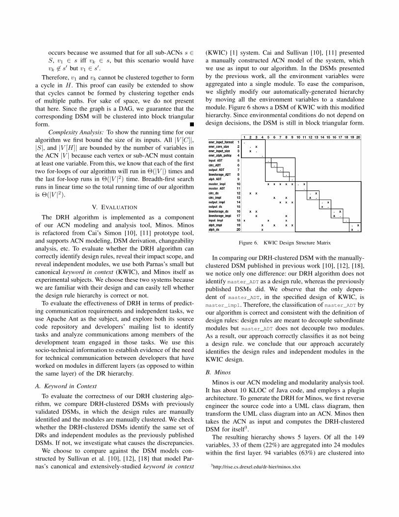
module. Figure 6 shows a DSM of KWIC with this modified
hierarchy. Since environmental conditions do not depend on
design decisions, the DSM is still in block triangular form.
Figure 6. KWIC Design Structure Matrix
In comparing our DRH-clustered DSM with the manually-
clustered DSM published in previous work [10], [12], [18],
we notice only one difference: our DRH algorithm does not
identify master_ADT as a design rule, whereas the previously
published DSMs did. We observe that the only depen-
dent of master_ADT, in the specified design of KWIC, is
master_impl. Therefore, the classification of master_ADT by
our algorithm is correct and consistent with the definition of
design rules: design rules are meant to decouple subordinate
modules but master_ADT does not decouple two modules.
As a result, our approach correctly classifies it as not being
a design rule. we conclude that our approach accurately
identifies the design rules and independent modules in the
KWIC design.
B. Minos
Minos is our ACN modeling and modularity analysis tool.
It has about 10 KLOC of Java code, and employs a plugin
architecture. To generate the DRH for Minos, we first reverse
engineer the source code into a UML class diagram, then
transform the UML class diagram into an ACN. Minos then
takes the ACN as input and computes the DRH-clustered
DSM for itself3.
The resulting hierarchy shows 5 layers. Of all the 149
variables, 33 of them (22%) are aggregated into 24 modules
within the first layer. 94 variables (63%) are clustered into
3http://rise.cs.drexel.edu/dr-hier/minos.xlsx

51 modules in the last layer. After carefully examining each
layer, we confirm that the design rules are correctly identified
and the locations of these DRs reflect their importance
level. For example, the first layer aggregates all of the most
influential decisions, such as util Graph interface and
minos P lugin interface.
We also find that the 51 modules in the last layer include
16 out of the total 18 plugins, each modeled as a block
with at least two variables. For example, the DRH clustering
plugin is modeled as 4 variables that are automatically
aggregated into a module in the last layer. The fact that
two plugins, Decomposer and cluster F ileWriter are not
in the last layer drew our attention. After examining the
dependencies shown on the DSM, we realized that unex-
pected dependencies had been introduced during evolution
and maintenance activities of the Minos software. Their
effect is to push these two plugins up the hierarchy. Based
on these observations from the Minos DRH, we now plan
to refactor those parts to improve its design.
In conclusion, as the designers and developers of Minos,
we confirm that the DRH clearly lays out the plugin archi-
tecture, and has even helped us identify some hidden poor
design decisions.
C. Apache Ant
To evaluate the feasibility of applying our approach to
a large-size, real-world project, we have experimented with
the popular, open-source Apache Ant project. Specifically,
we selected release 1.6.5 as our target, and extracted its
ACN model by reverse engineering its UML class diagram
from the code base. The Apache Ant UML model contains
around 500 classes and interfaces (including inner classes),
and almost 2,500 inter-element relations.
We derived an ACN from the UML class diagram, and
derived a DRH from that ACN, in about 15 minutes on a
2.16 GHz Intel MacBook Pro laptop with 3 GB of RAM, and
produced a DRH-clustered DSM that includes 12,596 pairs
of dependencies among about 1,000 variables. The DSM is
too large to fit in this paper, but is available at our website4.
DRH and Modularity Quality: According to Baldwin
and Clark’s option theory [8], since no modules depend
on independent modules in the last layer, they provide
the option to be substituted with better implementations
at minimal cost. Therefore, we can use the number of
independent modules in a system as an indicator of its design
quality. Despite having over 500 classes and 1000 variables
in its DSM, the Apache Ant DRH consists of only 11 layers.
When we compare this with, for instance, the maze game
example, we see that although Apache Ant has 40 times
the number of DSM variables, it has about only twice the
number of layers in its DR hierarchy. This means that most
modules in the system are aggregated horizontally within
4http://rise.cs.drexel.edu/dr-hier/ant-dr-hier.xlsx
layers, and the corresponding development tasks can be
highly parallelized. In addition, 52% of the tasks identified
are in the bottom layer of independent modules, indicating
that much of the system constitute options that can be
freely substituted. Both of these DRH-based characteristics
indicate that Apache Ant is well modularized, and easy
to maintain and evolve. Our concurrent work [19] further
investigates the use of the DRH for defining metrics on
software architecture modularity and stability.
Identifying Design Rules: When maintaining a software
system, especially an unfamiliar one, it is crucial not to
accidentally change parts of the system that are highly
influential. We are interested to see whether a DRH can
provide an ordering for design rules, in terms of their
influence, so that developers can be aware of these most
influential parts.
We examine the Apache Ant DSM and count the number
of dependencies to determine if the identified design rules
are indeed the most influential. The more other variables
depend on a given design rule, the more influential it is. Even
though a DSM is in block triangular form, it does not mean
that the variables furthest to the left are the most influential.
There may be some variables further to the right that depend
on the left-most variables, whereas a larger portion of the
rest of the system depends on them.
To verify if the identified design rules are the most influ-
ential, we use the DSM to count the number of dependencies
upon each variable. Figure 7 shows a graph of the average
and maximum number of dependencies for each layer of the
DR hierarchy. Notice that the vertical axis is in a logarithmic
scale. From the graph, we see that the variables in layer zero
have the most dependencies upon them. These high-level
dependencies indicate that if a variable in layer zero were to
change, it would impact much of the system. In other words,
the variables in layer zero are highly influential on the rest of
the system. Since both the maximum and average number of
dependencies decrease at each layer of the hierarchy (except
for between layer 2 and 3, where there is a slight increase
in the average number of dependencies), we conclude that,
almost always, each layer of the DR hierarchy for Apache
Ant is less influential than the one before it.
Figure 7. Dependencies Per Layer of Apache Ant DR Hierarchy

Identify Concurrent Tasks: We set out to test whether
the DR hierarchy can effectively identify modules that
correspond to independent and parallelizable tasks. Modules
located within the same DRH level are supposed to be
mutually independent, and thus constitute candidates for
independent task assignments. To validate that assumption,
we have taken a look at the work and communication
dynamics of the Apache Ant team, during the transition from
release 1.6.5. to the following release, that is, 1.7.0.
The method of our analysis descends from recent results
on socio-technical congruence, which indicate how to es-
tablish and analyze the coordination requirements between
developers working on concurrent tasks [3]. A coordination
requirement occurs when two developers, say, Alice and
Bob, are assigned to concurrent development tasks, and
those tasks require them to work on sets of software artifacts
that present some dependencies. In those cases, some form
of coordination between Alice and Bob is often necessary;
for example, Alice and Bob may exchange some technical
communication, which is often archived—particularly in
open-source projects—and hence traceable. On the other
hand, if Alice and Bob work concurrently only on mutually
independent modules, their need for coordination can be
greatly attenuated.
Based on the concept of coordination requirements, and
the semantics assigned to DSM dependencies and DRH
levels, we formulate the following hypotheses:
1) Technical communication between any two developers
who are engaged in concurrent work modules that
are located within the same hierarchy level should
be least intense. This hypothesis aims at verifying
that those modules are good examples of independent
task assignments, and do not present involved Ant
developers with coordination requirements.
2) Technical communication is likely to occur signifi-
cantly more frequently “across layers”, e.g., between
any two developers who are engaged in concurrent
work on modules located in different layers of the
hierarchy, and are dependent on one another. This
hypothesis aims at verifying that the layered depen-
dency structure provided by the DR hierarchy provides
a good indication of where coordination is needed, and
how it flows in the project.
For our analysis of Apache Ant, we have collected all
commits of Java code in the Ant SVN repository during
the development of release 1.7.0 (which lasted 19 months),
as well as all message exchanges within the developers’
mailing list of the project by the 14 active committers for
Apache Ant. We traversed the tree structure of each mailing
list thread, and considered as a communication exchange
between two developers any direct reply by one of them to
a message posted by the other.
To identify development tasks, we had to devise a strategy
to overcome the fact that the data set we could mine has only
sparse information linking tasks to specific code commits
within the source code repository. For example, only a
small portion (about 15%) of the change requests, bug fixes,
and other work items listed in the project’s Bugzilla are
referenced within the meta-data of Java code commits for
Ant 1.7.0. We have therefore used a sliding time window
to approximate the concept of parallel tasks with that of
concurrent work. For each of the 866 commits involving
any of the 1133 Java files, we computed a 2-weeks time
window, and considered any commits by other developers
within that window as concurrent work. (The choice of 2
weeks as the dimension of the time window was suggested
by examining the typical length of development tasks in
the project, mediated by the frequency of communication
exchanges observed within the developers mailing list.)
With this mechanism, all distinct pairs of developers
committing Java code within the same time window would
be considered as engaging in concurrent work. We were able
to identify 742 such pairs. We then proceeded to eliminate
those pairs in which either developer was responsible for
commits that had to do with simultaneous blanket changes
on a large number of files (more than 56, that is, 5% of the
overall Java code base). Commits of such kinds are typically
extraneous to actual development tasks. For example, they
occur when versioning, copyright or licensing information
needs to be updated in the comment section of all source
files; or when name change refactoring to widely used code
item is performed; or in case of other trivial housekeeping
activities on the code base.
That filter provided us with 653 developer pairs, upon
which we carried out further analysis. First of all, we
matched the commits by each developer to the variables
represented in the DSM. That way, we came up with a
list of the variables in each DSM module that could be
affected by the changes made to the Ant code base by a
pair of developers for a given time window. That provided
us with a basis to locate concurrent work by a developer pair
(say, Alice and Bob) within the DSM; we then proceeded to
extract the following subgroups from the population of 653
pairs:
1) If Alice and Bob have done concurrent work affecting
any pair of variables that have a dependency relation-
ship and are located in different DSM modules, we
count those pairs of variables and place them in the
Across Layers (AL) category;
2) If Alice and Bob have done concurrent work affecting
any pair of variables that have a dependency relation-
ship and are located in the same DSM module, we
count those pairs of variables and place them in the
Same Layer Same Module (SLSM) category;
3) If Alice and Bob have done concurrent work affecting
any pair of variables that are located in different
modules within the same layer of the DR hierarchy
(which by definition have no dependency), we count

Table IPROPORTION TESTS
χ2 p
SLDM < population 8.1256 < 0.01
SLDM < CR 23.723 < 10−6
CR > population 8.2521 < 0.01
those pairs of variables and place them in the Same
Layer Different Module (SLDM) category;
To complement that information, we counted the number of
mailing list exchanges between Alice and Bob within the
same time window.
For any time window and for any pair of developers, it
is of course possible that those developers have carried out
work that falls into more than one of the above categories.
That is important, because whenever a pair of developers
has a count > 0 for either the SLSM or AL category,
that indicates the presence of at least one coordination
requirement. In fact, 347 out of 653 pairs have a count of
AL > 0. There are also 144 pairs who have coordination
requirements originating from SLSM work, but the vast
majority of them are also included in the set with AL > 0:
only 9 pairs have a count of SLSM > 0 and AL = 0. All in
all, therefore, 356 pairs exhibited some form of coordination
requirement. (We will refer to them in the remainder as the
CR group.)
Similarly, we identified the 266 pairs who exclusively did
SLDM work in some given time window, that is, whose
SLDM count was > 0, and at the same time had both an
SLSM and AL count of 0 (We will refer to them in the
remainder as the SLDM group.)
Coming to technical communication data, out of the 266
pairs in the SLDM group, we found that 89 pairs exchanged
mailing list messages, that is, about 33%. In contrast, about
53% of the pairs in the CR group exchanged messages. That
percentage amounts instead to 43% when considering the
overall set of 653 pairs.
First of all, we set out to verify whether the difference
in proportion among these groups could be considered
significant. To that end, we carried out pairwise chi-square
tests of proportion between the various groups, and between
each group and the overall population. The results, which
are summarized in Table I, show how the differences in
proportion are indeed statistically significant. In particular,
it is confirmed with a very high degree of confidence that
the proportion of communicating pairs in the SLDM group
is significantly less than that of the CR group. Also the
proportion of communicating pairs in the SLDM group is
significantly less that that of the overall population; similarly,
the proportion of communicating pairs in the CR group is
significantly more than that of the overall population. All of
these observations are consistent with our hypotheses.
Since, however, a ratio of technical communication of
33% within the SLDM group seems high in absolute terms,
given the absence of coordination requirements in that
group, we carried out further statistical analysis, to try to
understand whether we could consider such as 33% ratio as
a sort of natural level of “chatter” within the communication
channel provided by the developers mailing list, whereas
higher ratios, such as 53% within the CR group could be
indeed described as a consequence of doing interdependent
concurrent work. To investigate that, we set out to verify the
additional hypotheses below:
1) The probability of communication between pairs in the
SLDM group is not correlated to the amount of SLDM
work they have concurrently carried out—that is, the
amount of different pairs of DSM variables affected
by their commits in the time window considered. In
contrast, the probability of communication between
pairs in the CR group is correlated to the amount of
of dependent work they have concurrently carried out.
2) The amount of communication—that is, the count
of messages, exchanged in the time window
considered—between those pairs in the SLDM group
that communicated is not correlated to the amount
of SLDM work they have concurrently carried out.
In contrast, the amount of communication exchanged
between pairs in the CR group that communicated is
correlated to the amount of of dependent work they
have concurrently carried out.
For the first additional hypothesis above, a point-biserial
correlation test between the count of pairs of DSM variables
touched by the 266 pairs in the SLDM group, and a
boolean variable indicating whether those developer pairs
communicated at least once provided us with an r-score
of 0.00206, which is consistent with no correlation. That
sharply contrasts with the result of the same statistical test
performed on the 356 pairs in the CR group. The r-score is
0.299, which denotes a strong positive correlation; moreover,
that correlation is extremely statistically significant, with
p < 10−8. These results confirm the hypothesis, since they
strongly suggest that the amount of SLDM work of a pair
of developers and their probability of communication do
not influence each other; on the contrary, the amount of
dependent work that produces coordination requirements
for a pair of developers and the probability of technical
communication between them are strongly linked.
For the second additional hypothesis above, we performed
a Pearson correlation test between the count of pairs of
DSM variables touched by the 89 pairs of developers in
the SLDM group who exchanged messages, and the number
of messages they exchanged. The r-score in this case is
-0.05626, which is again consistent with no correlation.
In the case of the 188 pairs of developers in the CR
group who exchanged messages, the same statistical test

returns an r-score of 0.189, which denotes a weak positive
correlation. That correlation is quite significant statistically,
with p < 0.01 (p = 0.0048). These result confirm our second
hypothesis, since they suggest that the amount of SLDM
work and the amount of communication do not influence
each other; on the contrary, the amount of dependent work
and the amount of communication are linked to each other.
From the comparative analysis above, we are confident to
conclude that the 33% ratio of communication within the
SLDM group is unlikely to be a consequence of any hidden
coordination requirements among modules in the same layer
of the DRH, or an artifact of some conceptual or technical
error in the DRH construction process. The statistical evi-
dence points instead to that ratio as being independent of
coordination requirements, and we can probably regard it as
a property of the communication channel we considered. The
result also suggests that the dependency structure derived
from the ACN model and clustered using DRH sufficiently
approximates the corresponding coordination structure.
Threats to Validity: A generic caveat is, of course, that
this study provides a single data point, which should be
further corroborated by more empirical investigation.
More specifically, one major assumption enabling our
statistical analysis regards our approximation of concurrent
development tasks by means of concurrent committed work
within a sliding time window. The choice of the size of that
window has a significant potential to influence our results.
Although we have been very careful in choosing what it
seemed to be a sensible size, it would be worth repeating the
analysis with different windows, to get some insight about
the sensitivity of our results to that parameter.
Our other most important assumption is about the medium
and method we used to analyze communication flows. That
analysis is, first of all, necessarily partial (we can only take
into account those communication acts whose traces are
persisted in some archive, and hence observable). Also, we
could have captured messages that are not related to any
development work whatsoever. However, our focus on the
developers’ mailing list ensures that the large majority of
discussions would be of a technical nature, and centered
upon the development tasks at hand. That is corroborated
from examination of random thread samples, and from the
fact that we could only identify 8 mailing list exchanges
between developer pairs that seemed to occur outside of the
context of some development activity (that is, with either
developer not engaged in any development work during
the considered time window). Finally, we mined mailing
list threads (i.e. a many-to-many communication medium)
which we had to map onto one-on-one exchanges. For that,
we leveraged—as discussed earlier—the tree structure of
the thread. That decision is of course a simplification of
how communication flows in a mailing list, and represents
a major factor in shaping our results. In the absence of
reliable knowledge of the intent of the poster, the only
additional insight could be provided by a deep semantic
understanding of the content of each message. However that
kind of analysis is definitely challenging and very costly,
and probably itself error-prone to an extent. Extending the
analysis to other communication channels in future studies
is therefore an important step.
VI. RELATED WORK
Organization of software as a layered, hierarchical struc-
ture has been advocated for many years. Dijkstra [20]
proposed this idea with the restriction that layers could
only communicate with adjacent layers. Today, the layered
style is popular in software architecture [21]. A major
difference with our DRH layers is that the modules in these
architectures are often defined based on classes, or other pro-
grammatic elements whereas the modules in our approach
are intended to indicate independent task assignments.
A DRH is different also from other well-known hierar-
chical structures, such as the “uses” hierarchy defined by
Parnas [22] and hierarchies defined according to conceptual
domains [20], [21]. For example, if a decision A in a
GUI layer is the only decision to depend on a decision
B in the business layer, then our DR hierarchy algorithm
will aggregate A and B into a task module because these
decisions can and should be made and changed together.
Another related area is project management and schedul-
ing. For example, Jalote and Jain [23] presented a scheduling
algorithm that considers task dependencies, available skills,
and resource constraints but their approach expects a task
graph as an input. Our approach complements their approach
in that we can use the DRH as an input task graph to their
algorithm. We then can use their algorithm to elaborate on
our hierarchy’s task assignments while considering other
issues such as resource constraints.
To determine the order of class integration when testing
object-oriented software, Briand et al. [24] discussed sev-
eral graph-based algorithms that identify strongly-connected
components (SCCs) and perform topological sorting to ob-
tain a partial ordering. Heuristics are presented to break cy-
cles within each SCC and reduce the effort of creating stubs
for tests. Although our approach also identifies SCCs in a
graph (for constructing the condensation graph), we do not
need to break cycles because cycles in our graph represent
cohesion and we identify modules based on this cohesion.
In addition, the modules identified by our algorithm do not
directly correspond to the SCCs of a graph.
The Lattix [14] tool automatically reverse-engineers a
DSM from a code base and provides several partitioning
algorithms to identify modules and reorder the DSM into
block triangular form. We tried to cluster the maze game
DSM to see if these algorithms can generate a clustering
similar to our DR hierarchy. The results show that even if
we manually feed Lattix with the dependencies derived from
the ACN (because Lattix itself does not detect indirect or

implicit dependencies between variables), the partitioning al-
gorithms either generate modules that are not cohesive—that
is, contain classes with dramatically different semantics—
or do not correctly reveal the order of design rules. For
example, it does not identify the Maze interface as a top
level design rule.
Our approach presents unique traits, which derive from
the fact that other object-oriented modeling methods do not
separate the interface and implementation dimensions for the
purpose of task assignment, nor identify and use indirect and
implicit dependencies.
VII. CONCLUSION
In this paper, we contributed a design rule hierarchy
(DRH) that can be used to predict coordination requirements,
to suggest task assignments that maximize parallelism, and
to reveal the impact scope of design rules. We evaluated this
hierarchy using the Apache Ant, Minos, and KWIC systems
as case studies. By investigating the source code repository
of Apache Ant and its developers’ mailing list, we show
that technical communication among developers working on
different modules in the same hierarchy layer is significantly
less intense than that required by developers working across
layers, supporting coordination predictions enabled by our
DRH. Using Minos and KWIC, we also show that the
hierarchy faithfully reveals design rules and their level of
importance. These experiments therefore demonstrate the
potential of our DRH model for reasoning and making
predictions about the interplay between design structure,
coordination structure and task assignment.
VIII. ACKNOWLEDGEMENTS
This work was supported in part by the National Science
Foundation under grants CCF-0916891 and DUE-0837665.
REFERENCES
[1] D. L. Parnas, “On the criteria to be used in decomposingsystems into modules,” Communications of the ACM, vol. 15,no. 12, pp. 1053–8, Dec. 1972.
[2] M. E. Conway, “How do committees invent?” Datamation,vol. 14, no. 4, pp. 28–31, 1968.
[3] M. Cataldo, P. Wagstrom, J. D. Herbsleb, and K. M. Carley,“Identification of coordination requirements: Implications forthe design of collaboration and awareness tools,” in Proc.ACM Conf on Computer Supported Cooperative Work, Nov.2006, pp. 353–362.
[4] J. D. Herbsleb and A. Mockus, “Formulation and prelimi-nary test of an empirical theory of coordination in softwareengineering,” in Proc. 11th ACM SIGSOFT Intl Symp on theFoundations of Soft Eng, Sep. 2003, pp. 138–137.
[5] C. R. B. de Souza, D. Redmiles, L.-T. Cheng, D. Millen, andJ. Patterson, “How a good software practice thwarts collabo-ration: The multiple roles of APIs in software development,”in Proc. 12th ACM SIGSOFT Intl Symp on the Foundationsof Soft Eng, Nov. 2004, pp. 221–230.
[6] C. R. B. de Souza, S. Quirk, E. Trainer, and D. Redmiles,“Supporting collaborative software development through thevisualization of socio-technical dependencies,” in Proc. IntlACM SIGGROUP Conf on Supporting Group Work, 2007,pp. 147–156.
[7] C. Amrit and J. van Hillegersberg, “Detecting coordinationproblems in collaborative software development environ-ments,” Information Systems Management, vol. 25, no. 1, pp.57–70, 2008.
[8] C. Y. Baldwin and K. B. Clark, Design Rules, Vol. 1: The
Power of Modularity. MIT Press, 2000.[9] M. Cataldo, J. D. Herbsleb, and K. M. Carley, “Socio-
technical congruence: A framework for assessing the impactof technical and work dependencies on software developmentproductivity,” in Proc. 2nd Intl Symp on Empirical Soft Engand Measurement, Oct. 2008, pp. 2–11.
[10] Y. Cai, “Modularity in design: Formal modeling and auto-mated analysis,” Ph.D. dissertation, University of Virginia,Aug. 2006.
[11] Y. Cai and K. Sullivan, “Simon: A tool for logical designspace modeling and analysis,” in Proc. 20th IEEE/ACM IntlConf on Automated Soft Eng, Nov. 2005, pp. 329–332.
[12] ——, “Modularity analysis of logical design models,” in Proc.21st IEEE/ACM Intl Conf on Automated Soft Eng, Sep. 2006,pp. 91–102.
[13] S. Wong and Y. Cai, “Predicting change impact from logicalmodels,” in Proc. 25th IEEE Intl Conf on Soft Maintenance,Sep. 2009.
[14] Lattix Inc., “The Lattix approach whitepaper,”http://www.lattix.com, 2004.
[15] E. Gamma, R. Helm, R. Johnson, and J. M. Vlissides, DesignPatterns: Elements of Reusable Object-Oriented Software.Addison-Wesley, Nov. 1994.
[16] A. Egyed, W. Shen, and K. Wang, “Maintaining life per-spectives during the refinement of UML class structures,” inProc. 8th Intl Conf on Fundamental Approaches to SoftwareEngineering, Apr. 2005, pp. 310–325.
[17] N. Sangal, E. Jordan, V. Sinha, and D. Jackson, “Usingdependency models to manage complex software architec-ture,” in Proc. 20th ACM SIGPLAN Conf on Object-OrientedProgramming, Systems, Languages, and Applications, Oct.2005, pp. 167–176.
[18] K. Sullivan, W. G. Griswold, Y. Cai, and B. Hallen, “Thestructure and value of modularity in software design,” in Proc.8th ACM SIGSOFT Intl Symp on the Foundations of Soft Eng,Sep. 2001, pp. 99–108.
[19] K. Sethi, Y. Cai, S. Wong, A. Garcia, and C. Sant’Anna,“From retrospect to prospect: Assessing modularity andstability from software architecture,” in Proc. 8th WorkingIEEE/IFIP Intl Conf on Software Architecture, Sep. 2009.
[20] E. W. Dijkstra, “The structure of the “THE”-multiprogramming system,” Communications of the ACM,vol. 11, no. 5, pp. 341–6, May 1968.
[21] L. Bass, P. Clements, and R. Kazman, Software Architecturein Practice, 2nd ed. Addison-Wesley, 2003.
[22] D. L. Parnas, “Designing software for ease of extension andcontraction,” Transactions on Soft Eng, vol. 5, no. 2, pp. 128–138, Mar. 1979.
[23] P. Jalote and G. Jain, “Assigning tasks in a 24-hour softdevelopment model,” in Proc. 11th Asia-Pacific Soft EngConf, Dec. 2004, pp. 309–315.
[24] L. C. Briand, Y. Labiche, and Y. Wang, “An investigation ofgraph-based class integration test order strategies,” Transac-tions on Soft Eng, vol. 29, no. 7, pp. 594–607, Jul. 2003.