Embed Size (px)
Citation preview

G-402
DESIGN REQUIREMENTS FOR SRBPRODUCTION CONTROL SYSTEM
FINAL REPORT
VOLUME II
SYSTEM REQUIREMENTS AND
CONCEPTUAL DESCRIPTION
SUBMITTED BY:
AT, KEARNEY, INC
https://ntrs.nasa.gov/search.jsp?R=19810023637 2020-03-26T22:45:58+00:00Z

DESIGN REQUIREMENTS FOR THE SRB»
PRODUCTION CONTROL SYSTEM
VOLUME II
SYSTEM REQUIREMENTS AND
CONCEPTUAL DESCRIPTION
TABLE OF CONTENTS
SECTION III - BUSINESS SYSTEM REQUIREMENTS
SECTION IV - BUSINESS SYSTEM DESCRIPTIONi „'
SECTION V - COMPUTER SYSTEM DESCRIPTION

Ill - BUSINESS SYSTEM REQUIREMENTS
INTRODUCTION
In the development of the business system for the SRB auto-
mated production control system, special attention had to be paid
to the unique environment posed by the space shuttle. The issues
posed by this environment, and the means by which they were ad-
dressed, are reviewed in this section.
First, there is a discussion of the change in management
philosophy which will be required as NASA switches from one-of-a-
kind launches to multiple launches. Second, the implications of
the assembly process on the business system are described. These
issues include multiple missions, multiple locations and facilities,
maintenance and refurbishment, multiple sources, and multiple con-
tractors. Third, the implications of these aspects on the auto-
mated production control system are reviewed. This includes an
assessment of the six major subsystems, as well as four other
subsystems. Finally, some general system requirements which flow
through the entire business system are described.
MANAGEMENTPHILOSOPHY .
Manned space flight has in the past been in one-of-a-kind
disposable launch vehicles and space craft. The management sys-
tems which have evolved to support this business environment are
directed at:
1. Elimination of risk, ensuring astronaut safety at
at any cost.
' ' Kearney.- Management Consultants

: • in - 2
2. Assurance of design integrity through detailed con-
trol techniques which include:
(a) Tight design change approvalcontrol.
(b) Configuration control with"delta" reports.
(c) Detailed flightreadiness reviewprocess.
3. Tracking of materials and assemblies through inspec-
tion, storage, work-in-process and assembly into the "as built"
configuration.
Shuttle operations will require a shift in management phi-
losophies. The reasons for this shift are the stability of the
launch vehicle design, the reuses of launch vehicle and shuttle
craft and the increasing emphasis on cost effectiveness. This
shift in management philosophy will support the following mission
objectives:
1. Ensure crew safety.
2. Contain value added per flight.
3. Stabilize design for multiple mission component use,
4. Reuse or refurbish assemblies and components as
rapidly as possible.
5. Maintain the minimum manufacturing resources re-
quired to meet launch schedules.
This shift is a reorientation to a manufacturing management
philosophy for NASA and the SRB contractor. This manufacturing
Kearney: Management Consultants

Ill - 3
management philosophy will include the following elements:
1. Customer service. Emphasis will be directed at
achieving integration timetables with delivery of products of
acceptable quality. Customer service would be monitored through:
(a) Promise date performance with re-gard to product delivery commit-ments to integration activities.Key deliveries in the SRB processwould be aisle transfer, stackingcompletion, and clean and disas-sembly dates.
(b) Delivered product acceptance anal-ysis reports such as rework re-quirements or work remainingreports. This would apply torefurbishment, assembly, stackingand cleaning and disassemblyactivities.
2. Productivity, utilization and cost control. These
elements define the cost effectiveness of manufacturing resources
employed and require the following:
(a) Balanced resource availabilityplans to resource requirements;e.g., balance the mechanicaltechnicians available to theoperations scheduled which requiremechanical technicians.
(b) Facilities design optimization.
(1) Use of cost effective faci-lities, buildup stands, andequipment.
(2) Facilities layout optimiza-tion, particularly in criticalfacilities such as the HotFire Test Facility.
(c) Facilities schedule loading; i.e.,time required in the facilityversus time available.
Kearney: Management Consultants
Ill - 4
(d) Manpower requirements planning ... .and schedule loading.
(e) Materials requirements planning,in the form of LRU requirementsby serial number, by date, as wellas the back-scheduling of the re-furbishment required to providethese serially numbered LRUs bythe required date, within theconfiguration constraints.
(f) Standard costing and variance re-porting, in the form of standardor expected cost per missionversus actual cost.
(g) Operations performance tracking,in the form of standard refur-bish'ment operations and standardtime per operation.
3. Manufacturing risk management. Risk can be managed
through the proper design of the production control System. Some
techniques used to manage risk are:
(a) Contingency capacity planning offacilities, manpower, and mate-rials availability, in the eventof such things as technical skilldisqualification, minor or majoraccidents at facilities, etc.
(b) Calculated risk of stock-outs orshortages and buffering risk withsafety stock or spares. This isparticularly critical due to theunknown condition of retreivedSRBs as subsequent missions areplanned or readied.
(c) Exception alerts highlighting anysignificant deviation from plannedactivity. This is a techniqueneeded to identify potential.bot-tlenecks such as unavailable GSEas early as possible.
(d) Priority action management sys-tems. This is a method to
Kearney.- Marvvjement Consultants
Ill - 5
expedite critical work throughthe refurbishment and subassemblyfacility. The high volume ofschedule juggling needed is arequirement which an automatedscheduling system must accommo-date, due to the large number ofserially numbered parts in thesystem at one time.
4. Rebuildable SRB Management Control. SRB refurbish-
ment places unique requirements on the production control system
used. These include:
(a) Facilities, manpower, and mate-rials planning based on bestestimate of needs. These esti-mates may be reasonably accurateaverages over time but are inac-curate for the refurbishment ofan individual SRB.
(b) Management control and engineeringcompatability of hybrid mixturesof new and refurbished components.
(c) Cost tracking hybrid SRBs.
5. Evolution of Design Flexibility. Although design
stability is desirable, design emphasis will evolve through the
following phases:
(a) Flightworthiness design.
(b) Weight control design.
(c) Cost minimization design.
6. High Operations Performance and Cost Visibility.
Orientation to a "least value added per flight" management
philosophy requires tracking of resource productivity and com-
parisons to the planning assumptions used. Typical productivity
Kearney: Management Consultants

I'ii -
reports are:
(a) Operations budgeting and' vari-ance reporting, initially byflight and SRB; later by activityarea, labor skill level, andmajor component; e.g., the aftskirt.
(b) Facilities utilization reporting.
(c) Manpower productivity performancereporting, by refurbishment andsubassembly Work AuthorizationDocument (WAD), by work team, andby component. ,
(d) Inventory planning and performancetracking reports, by LRU, bulkmaterial; e.g., cork; and bysubsystem.
(e) Tools and GSE planning, schedu-ling and performance reports.
(f) Actual and standard cost report*ing, by mission, SRB, and majorcomponent.
*» (.g) Value added reporting per flightand SRB.
r •
(h) Delivery promise reporting at keydelivery times; e.g., aisle trans-fer.
7. Coordination with Shuttle Control. The interdepen-
dence of multiple contractors requires that integration performance
be tracked. Some of these performance elements are:
(a) Multiple contractor schedule inter-dependencies.
(1) Delivery performance in theform of providing services;
, e.g., tube cleaning, at the' scheduled time.
(2) Hazardous operations, such asordnance ring installation.
Kearney: Management Consultants

Ill - 7
(3) Shared GSE by several sub-contractors.
(b.) Contract performance feedback.
(1) Product quality insofar asrework time and cost.
(2) Delivery performance andprogress status.
(3) Actual SRB and per-flightcost compared to estimatedor "standard".
MULTIPLE MISSIONS
Unlike previous manned missions undertaken by NASA, the
Space Shuttle Program is based on the reuse of two of the three
major modules in the project. One of these modules, the two
Solid Rocket Boosters, are recovered after each flight, cleaned^
inspected, tested, refurbished, and reassembled for use in a
future flight. This multiple mission provision coupled with
the principle of minimum value (cost) added to each subsequent
flight requires the following considerations to be addressed by
the business system:
1. Provide the ability to support multiple design
effectivities .across the planning horizon.
2. Provide different planning horizons dependent upon
the lead or acquisition time of the resource; e.g., technical man-
power, facilities and SRB components. The different planning
horizons include:
(a) Long-range manpower planning(five years or program remaining).
(b) Short-range manpower planning(six months by week).
Kearney: M^ivjement Consultants

Ill -, 8>
(c) Facilities and work center plan-ning (five years or program re-maining ).
(d) Facilities loading (six months byweek).
(e) Materials by commodity clas.s(by POPs or program remaining).
(f) Materials by item (by vendor leadtime).
(g). Critical GSE (by POPs).. (
(h) GSE loading (six months by week)..
3. Provide the ability to support hybrids of new, and;. . s
refurbished subassemblies, parts and components.
4. Provide for the eventual stabilization of hardware
design while maintaining the flexibility of providing multiple
design changes, during the initial phases of the. program.
5. Support a launch schedule going from t;wo flights per
year to in exce.ss of 50 flights per year (for two locations).^ . . . . . . .
6. Provide for action reporting on an "exception"
basis, which, in critical cases, will require management action
needing manual (human) decisiqnmaking.
MULTIPLE LOCATIONS
Due to the eventual expansion of the STS program, it is antir
cipated that actual refurbishment and assembly must be acc.omp.lis.hed
at more than one location. Currently, Kennedy- Space Center in
Florida and Vandenberg Air Force Base in California are the anti-
cipated locations.
Because of this requirement the following considerations must
. Kearney: A/Urvagement Consultants

Ill - 9
be taken into account:
1. Data files used for all planning, scheduling,
tracking, performance monitoring, and job costing must be identical
at the start of each day, where shared records are needed. How-
ever, this is not to imply that the work centers, actual SRB
configurations, physical working facilities or work/material
routings must be identical.
2. Refurbishment and assembly at each location will be
controlled at that location and therefore, the planning, control,
and tracking will be discrete at that location.
3. The POPs will be used with the master mission pro-
file to "drive" the system at each location, based on the discrete
launch schedule for each location.
4. In order to maintain minimal safety stock inven-
tories, it is anticipated that parts, components and subassemblies
may need to be transferred from one location to the other. This
could provide for shared safety stock and perhaps reduce the cost
of such safety stocks. Therefore an on-line, real-time data
communication link between the two locations is recommended.
5. The system must provide access to all history files
of parts, testing results, and actual refurbishment and assembly
activities at both locations.
6. It is anticipated that due to the huge amounts of
data storage required, a mainframe computer will be necessary
at each location.
Kearney: Marviyrnent Consultants
- 10
MULTIPLE FACILITIES . . " " ' - ' ' ' " ; '
Based upon the existing facilities located at KSC, consi-
dering the distance between facilities as well as the physical
size of each facility, the following requirements are noted:
1. At least one and possibly multiple data collection
terminals will be needed in each facility. One "possible
exception" to this requirement might be at Pads 39A and 39B.
2. Based on current plans the following types of activ-
ities have been identified for the above requirement:
(a) Ref urbishment/Subassembly.
(b) Testing and Inspection.
(c) Assembly.
(d) Material storage (short and longterm).
(e) Disassembly and Cleaning.
(f) Receiving. ,
3. Specific locations (at this time) include the fol-
lowing locations where data collection would be recommended:
(a) Hangar AF.
(b) Hangar N.
(c) VAB (High and Low bays).
(d) Hot Fire Testing.
(e) VAB-1N4 and 1F4.
(f) Pads 39A and 39B (Possibly).
(g) Parachute facility (minor).
(h) Battery Lab.
( i ) Gyro Lab.
KeArney: Management Consultants

Ill - 11
4. An ''-intelligent terminal" is recommended for use
as the data collection device referred to above. The exact terminal
type; i.e., data collection or minicomputer, will be specified in
the computer systems requirements.
5. Status of material must be known at each work center
for each shift, A work center would be equivalent to the current
area where major activities occur, such as, aft skirt build-up
stand, forward skirt buildup stand, Hangar N test rings, MLP (by
levels), etc. In some cases a work center may be associated with
an entire facility; e.g., the Hot Fire Test Facility; but if
multiple work areas are developed for multiple activities and
tests to take place simultaneously, each could be considered a
work center.
6. Several work centers may be combined into work cen-
ter groups, using one data collection terminal.
7. Data collection devices at each work center group
do not necessarily have to be tied together "on-line" within each
facility, but do require linkage at the end of each shift.
8. Data collection devices at work center groups of
sufficient data entry volumes will require the ability to produce
hard copy of labor to be performed, material or GSE requirements,
or routing information.
9. Data collection devices used at work center groups
will accept information about work progress on a "real-time"
basis throughout the shift.
10. These devices will provide status reporting infor-
mation to the complex (KSC or VAFB) mainframe at the end of each
Kearney.- Management Consultants

Ill - 12
shift (batch).
11. These devices however, must provide "real-time" file
information from the mainframe computer.
MAINTENANCE AND REFURBISHMENT
(a) Flight Hardware
In order to ensure in-flight safety and operational success,
a detailed (refurbishment) schedule has been developed by NASA;
This refurbishment schedule can be summarized as follows:
1. Organization Refurbishment. Refurbishment performed
in-place on vehicle subsystems and maintenance.performed on related
support equipment in direct support of the turnaround flow.
Organizational refurbishment/maintenance includes scheduled and
unscheduled, preventive and corrective actions required tb irispect,
calibrate, service, replace, in-place repair and modification,
and reverification of subsystems and associated components.
2. Intermediate Refurbishment. Refurbishment performed
in direct support of organizational refurbishment arid maintenance,
and involves disposition, repair, service, calibration, modifica-
tion, arid verification pf items removed during organizational
refurbishment. Its phases normally consist of calibrating, re-
pairirig, or replacing damaged or unserviceable parts, components,
or assemblies.
3. Depot Refurbishment. Refurbishment performed by
designated sources; e.g., manufacturers, USAF Air Material Areas,
and NASA Development Centers, etc., because equipment, facilities*
Kearney: Management Consultants

• . Ill - 13
or skills are not economically available at the intermediate main-
tenance levels. Depot refurbishment includes providing technical
assistance to the intermediate refurbishment levels.
In addition, all refurbishment functions are classified into
different types: unscheduled, scheduled, or servicing tasks.
1. Unscheduled Refurbishment. Unscheduled refurbish-
ment encompasses two types: corrective action and postflight
inspection. The corrective action includes the investigation
and correction of discrepancies noted during the previous flight.
Further corrective action tasks will be initiated after com-
pletion of visual postflight inspection. The function will be
accomplished by providing a high level of confidence for system
performance evaluation and fault isolation to a single defective
line replaceable unit (LRU) in the minimum amount of time and with
a minimum of special support equipment. Although in-place repair
may be used for simple refurbishment acts, the primary method will
be replacement of the faulty LRU with a like serviceable unit.
Following LRU replacement, the subsystem function will be re-
verified. Isolation of LRU malfunctions and verification of
repair will be completed by replacement of the most readily re-
placeable subassembly level of equipment. Following repair, the
operating condition of the LRU will be verified and necessary
alignments and adjustments will be completed before the LRU reaches
the status of a ready-issue spare.
2. Scheduled Refurbishment. Consists of a preplanned
Program of refurbishment with particular emphasis on retaining
Kearney: Management Consultants

Ill - 14
solid rocket hardware in specified condition by providing system-
atic inspection and detection, to prevent incipient failures.
The tasks are scheduled on the basis of flying time, equipment
operating time or cycles, and/or calendar time.
3. Maintenance Servicing. Servicing, within the allo-
cated portions of che operational turnaround cycle, includes the
routine ground operations required to prepare the vehicle for
launch and mission requirements.. These functions include replenish-
ment of all expendables or consumables and life support elements.
Finally, in order to fully define the parameters of a compre-
hensive refurbishment concept, equipment replacement has been
grouped into three categories:
1. Predictive Items. Removal and replacement of an
item is based upon the item's life having approached or achieved
a previously defined limit. The assessments of the limit are
made at intervals determined by the item's failure characteristics
and may consist of inspections, measurements, tests, or any other
means not requiring teardown or removal of the item from the
vehicle.
2. Fly-to-Fault Items. This classification is reserved
for particular items which are not mission essential, do hot af-
fect flight safety, and that remain in place until an assessment
of the item's condition indicated that removal is required. The
item must fail in a random fashion and detection of the item's
malfunction requires no expenditure of refurbishment or maintenance
man-hours.
. ' . Kearney: Management Consultants

3. Scheduled. Removal and replacement of these items
is based solely on a time-dependent failure mode, regardless of
their condition when removed. The scheduled replacement classi-
fication will include only those items which cannot be classified
as predictive or fly-to-fault. The removed item undergoes a tear-
down inspection and/or overhaul.
Based on the above summary of SRB refurbishment requirements,
as well as other observations made during the audit phase of
this engagement, the following are business system requirements:
1. Ability to track parts, components, and subasssem-
blies by part/serial number and level and type of refurbishment
required/performed.
2. Ability to flag required parts refurbishment
scheduled but not yet performed.
3. Ability to sort by type or level of refurbishment
required/performed, keying on discrete part number/serial number.
4. Ability to maintain permanent file of actual versus
planned refurbishment performed by type and level.
5. Ability to accumulate refurbishment performed by
part/serial number and to compare to estimated service life deter-
minations; by number of previous flights and by number and type
Of previous refurbishment activities.
6. Ability to differentiate part, component, and sub-
assembly items by part/serial number in inventory based on the
actual refurbishment performed.
Kearney: Management Consultants

Ill - 16
(b) Ground SupportEquipment
Due to the critical nature of certain types of GSE, it ".is
necessary to identify and control such GSE as an integral part
of the overall business system. While it is recognized that a
computer package may not include the scheduling and control of
"maintenance equipment" .such as GSE or buildup stands, in its
mainline operation, a future modification or enhancement will
probably be necesary to incorporate this "function" into the
system. Even then, a great deal of manual manipulation will be
required due to "shared" use of some GSE by contractors other
than USBI. . . . - ' .
Therefore, either a fully manual or semiautomated system
will be necessary to provide scheduling and tracking capabilities
within the overall system environment. Key requirements are
identified as follows:
1. Provide information as to specifically what GSE is
required during scheduled refurbishment or assembly across a
several-week time horizon.
2. Identify what "condition" of GSE is necessary in
order to provide the required function.
3. Identity what "condition" the GSE is actually in
and determine the disparity (if any) between the actual and re-
quired condition.
4. Provide estimated schedules of servicing or
maintenance requirements to critical GSE in order to provide
Kearney-. Management Consultants
. . . : III - 17
such GSE at the time it is "required" per the computer system
schedules. This'might include calibration, proofloading or
normal preventive maintenance.
5. Flag GSE which is not in a serviceable state, with
enough lead time to perform GSE proofing or service prior to the
estimated requirement time.
6. Maintain on a permanent file specific information
related to GSE which is required in order to provide uninterrup-
ted serviceability and functional operation. Included might be:
(a) Type of service required.
(b) Dates of past service.
(c) Estimated future service require-ments.
(d) Problems, discrepancies, or modi-fications which have taken placein the past.
(e) Other specific considerations.
MULTIPLE SOURCES.
Due in part to the number of vendors supplying components
to the SRB project, as well as the long and variable lead times
and cost of individual parts, the following required capabilities
of the system have been identified:
1. Provide current on-order information to procurement
by the following key classifications:
(a) Subsystem or commodity classi-fication.
(b) Vendor.
(c) Bill of material effectivity.
Kearney: Management Consultants

I'll - 1!8
(d) Need date versus promise date. '" • .
(e) Parts in need of expediting.
2. Track vendor performance data by individual vendor
and summarize performance by vendor class or LRU or subsystem
level code. '
3. Report performance data of vendors. This may 'be spe-
cified in the following areas:
(a) Quality, including "acceptable"deviation from specifications.
(b) Actual cost versus budgeted cost.
(c) Promise date versus need date.
(d) Actual receipt date versus promisedate.
(e) Overall material flow continuity.This is particularly important in
. • . providing aisle transfer and launchdate integrity. This might be ex-pressed in terms of "number of de-lays caused by vendor", etc.
(f) Vendor production milestone per-formance, in terms of achieving aLRU refurbishment or replacementwithin the time specified.
Other system considerations are included in the "Purchasing11
section of this business system requirement document<
MULTIPLE CONTRACTORS .
Recognizing that several prime contractors and numerous
subcontractors are involved in the STS project, the following re-
quirements have been identified:
1. USBI will require a system responsive to their needs
Kearney: Management Consultants
. 1 1 1 - 1 9
as well as NASA's needs, but not necessarily interface directly
with systems of other contractors, for example Thiakol.
2. Some type of interface will be required, however,
and it is anticipated that such interface will be manual in nature,
3. Since SRB refurbishment and assembly schedules are,
in part, contingent upon not only the overall mission profile and
POP, but are also contingent upon detailed operating schedules
of other contractors, communication and coordination between
USBI and these other contractors is of major importance, and
must be given the level of authority required to initiate action.
4. The overall system (manual procedures and computer
systems) must, therefore/ be able to respond easily to changes in
schedules, material requirements, and resource requirements based
on conditions which arise outside of USBI's scope or control.
5. It is anticipated that this response will be based
on manual inputs and overrides by USBI management. :
6. Resources to be shared with other contractors will
be scheduled using the USBI automated production control system
but are subject to a high degree of variation and "schedule non-
compliance" due to unknown, or unforeseen circumstances resulting
from problems caused by other contractors.
7. It is anticipated that NASA will provide, in addi-
tion to general guidelines and procedures, a specific scheduling
system for "shared resources" in order to reduce the slippage
impact among contractors. .
Kearney: Management Consultants

111 - 20
MASTER SCHEDULING/RESOURCE PLANNING . •
The system must be able to: . ='•;. ;
1. Interpret the mission launch schedule into an aisle
transfer schedule for major components such as aft skirt, frustum,
e tc.
2. Determine, if these major components can meet aisle
transfer requirements.
3. Schedule refurbishment of major components and
assemblies.- ^
4. Assign a specific refurbished and new major assem-
blies to a specific SRB flow; i.e., effectivity control for hybrid
SRBs.
5. Determine ability to produce to launch and to .aisle
transfer schedules.
(a) Determine time-phased resourcerequirements such as:
(1) Facilities by critical workcenter, e.g., Hot Fire TestFacility.
(2) . Manpower by labor certifica-tion, e.g., Electrical Tech-nician by specified skillcertification.
(3) Materials by commodity clas-^sification or criticalcomponent.
(b) Match resource requirements a-gainst a time-phased resourceavailability plan and reportresource capacity information.This resource capacity informa-tion will include identificationof overcapacity resources, and
Kearney: Management Consultants

Ill - 21
. underutilized resources. Forexample, if for one month hot firefacilities require 120% of theplanned capacity, then an actionreport will identify this as apotential bottleneck facility.
(c) Balance resource requirements andthe'resource availability plan.This will require adjustments tothe requirements schedule and theavailability plan. Adjustmentsto the resource requirementsschedule may involve backing offthe aisle transfer date to anearlier date, thereby moving peakcapacity demands to an earliertime period which has availablecapacity. Adjustments to the re-source availability plan mayinclude the reallocation of re-sources with excess capacity toresources with deficient capaci-ties; or may include the reduc-tion of resources having excesscapacity; or the acquisition ofresources having deficient capa-city .
(d) Determine financial requirementsneeded to produce. This will in-clude costing of resource require-ments to determine SRB costs, andwill also include costing of theresource .availability plan todetermine future budget require-ments implicit in the missionlaunch and aisle transfer sched-ules. The determination offinancial requirements demandedto meet schedules will be thebasis of Operations Budgets,which will budget materials,manpower, facilities and over-head/ and will monitor key per-formance milestones. Theseperformance milestones willinclude:
(1) Launch compliance.
Kearney: Management Consultants

Ill - 22
(2) Aisle transfer compliance.
(3) Facilities acquisition, or' disposal.
(4) Manpower skill certificationbuildup.
(5) Materials acquisition byclass or critical component.
(6) Safety limitations.
(e) Consider SRB recovery loss pro-jections,
6. Reschedule for changes with minimal data manipula-
tion. This will require identification of schedule change needsi •
and resource change needs which are caused by a launch or aisle
transfer schedule change/ while not permitting the system to
"overreact". For example, minor or insignificant change.s such as a
one-day lag in scheduled refurbishment, should not create an alert
for action, but instead automatically provide for a "net-change".
7. React quickly to planning exceptions such as:
(a) Losses of SRBs on recovery. ,
(b) Launch schedule changes,
.(c) Shutdown of work centers,
(d) Financial cutbacks.
8. Simulate "what if" situations and determine impact
on:(a) Launch schedule compliance capa-
bility.
(b) Aisle transfer schedule compliancecapability.
(c) Resource requirements.
(d) Resource availability plans.
Kearney: Management Consultants

1 i 1 - -^ J
(e) Operations budgets.v
These "what if" situations may include changes in:
(a) Launch schedules.
(b) Aisle transfer schedules.
(c) SRB recovery loss rates.
(d) Manufacturing and assembly cycletimes.
(e) Design configuration.
(f) Resource usage rates.
(g) Resource availability plans,
(h) Resource costing data.
9. Project resource plans and operations budgets for
multiple years. This will allow automation of the POPs process
and will facilitate total program cost projections, currently
performed by BOSIM.
MATERIALS REQUIREMENTSPLANNING
The system must be able to:
1. Project time-phased material requirements over a two-
to three-year materials planning horizon. These projections will
require:
(a) A producible master schedule de-picting SRB flow launch schedules,and new or refurbished major as-sembly aisle transfer schedules.
(b) Material release offset lead timesto stage the release of materialsfor. each assembly.
(c) A structured bill of material foreach SRB effectivity to be produced.
Kearney: Management Consultants
Ill « 24
(d) A fore'casted attrition bill ofmaterials which depicts the prob-ability of replacing any componentduring the major subassembly/refurbishment process. ,
• '' i(e) A bill of materials which reflects
the manufacturing process ratherthan the engineering design logic.This may include creation of addi-tional levels in the bill whichreflect stages of assembly ortesting. This is often accom-plished by the use of pseudo billsin the engineering bill, therebyemulating the manufacturing processflow of materials.
2. Compare the projected materials requirements against
planned inventory availability to determine net material require-
ments. This netting will require:
(a) An inventory control system whichhas the following features:
(1) Item reservations againstexplicit requirements.
(2) Receipt planning by due date.
(3)' Linking (pegging) of plannedreceipts or on-hand items toexplicit requirements.
(4) Reorder policies for manu-, factured items.
(5) Refurbishment/subassembly andstacking cycle times.
(6) Reorder policies for pur-chased items.
(7) Purchasing lead times.
(8) Maintained safety stocks.
(9) Nonactive item locationsfor exclusion from availablestock.
Kearney: Management Consultants
Ill - 25
(b). Differentiated types of net re-quirements. These will include:
(1) Purchase requisition recom-mendations grouped by commo-dity class and consolidatedby item for economic orderingof materials.
(2) Recommended shop orders forone item at a time to facili-tate effectivity control andconfiguration management.However, the timing of theshop orders will be consol-idated to achieve productioneconomies of scale.
3. Track rescheduling by the degree of order flexibility.
This will require three types of orders:
(a) Planned orders. These orders donot yet have resources committedto them. Therefore reschedulingis done for any change in materialrequirements.
(b) Firm orders. These orders haveresources committed but are notreleased. Therefore reschedulingis done if material requirementschanges are significant.
(c) Released orders. These are pur-chase orders released to vendorsand shop orders released to dis-patching. These orders areexpedited or deexpedited ratherthan rescheduled.
4. Firm up the "as designed" configuration for an SRB
flow effectivity. This will require freezing design changes for
a specific flow or mission. This "frozen" configuration will be
used as the benchmark design for comparison to the "as built"
configuration. This will not mean, however, that the design must
be frozen across three years. .
Kearney: MArvpjement Consultants

Ill - 26
5. Facilitate effectivity and configuration control..
This will be accommodated by:
(a) Maintaining "as designed" and"as built" configuration dataon each serialized item ininventory, if modifications havebeen made to this item sinceserialization was initiated.
(b) Identifying all engineering changesrequired to upgrade effectivitiesof each serialized item.
(c) Tracking "as built" data as eachserialized item is used in a sufcH-assembly.
(d) Identifying item/assembly crossreference to parent drawing aswell as location on drawing.
(e) Identifying substitution possi-bilities for flightworthyeffectivity alternatives to aspecific item number.
(f) Tracking engineering change statusand milestone performance.
(g) Allow assembly of hybrid SRB flowsof a mixture of new and refurbishedand of multiple design effectivi-ties. These mixtures must be welldocumented for flightreadiness re-views and will have prior approvalfrom flightworthiness inspectorsand/or from a design compliancereview board.
6. Facilitate ease of material requirements manipula-
tion. This will be improved by:
(a) Automated bill of material require-ments explosion and inventory netting.
(b) On-line real-time adjustments.
(c) Net change systems logic.
Kearney: Management Consultants
III - 27
CAPACITY REQUIREMENTSPLANNING/RESOURCELOADING
The system must be able to:
1. Extrapolate the time-phased materials requirements
for manufactured and assembled items into a detailed resource
capacity loading by week over a six-month horizon. The resources
loaded will include:
(a) Work centers and facilities.
(b) Labor skill certifications.
(c) GSE and tools.
2. Identify surplus and deficient resources. This will
highlight capacity work centers or labor skills and identify all
shop orders which may cause that resource capacity to be exceeded.
Capacities will be based on a "practical" capacity for each resource,
but reports will include a theoretical maximum capacity.
3. Combine preventive maintenance schedule resource
loading with that of shop orders, but allow preventive maintenance
orders to have alternative scheduling priorities. For example,
orders could be:
(a) Mandatory at.a particular time.
(b) Mandatory before any other workusing a specific work center orGSE.
(c) Discretionary when resources be-come available.
(d) Discretionary with increasingpriority.
(e) Other priorities.
Kearney: Management Consultants
Ill - 28
4. Block labor certification time from "available for• ' - • • ' • ' » " •
production". This will be required for: '
(a) Sick and personal time contin-gencies.
(b) Department meetings.
(c) Vacation.
5. Project capacity loads based on best estimates of
refurbishment needs.
6. Adjust resource requirements based on work-in-process
decisions. For example:
(a) Routing changes to alternate opera-tions or work centers. This willprobably remain a manual activity.
(b) Routing changes to added operationsand resource requirements. Thiswould include test process sheets,problem reports or discrepancy re-ports.
(c) Time compression or expansion de-cisions .
(d) Appended routing segments based ohrefurbishment test results. Theseresults will list:
s
(1) Further tests or operations tobe performed.
(2) Line replaceable units to bereplaced.
(e) Appended routings required to reworksubstitute effectivities up to therequired effectivities. This willinclude routings to incorporateengineering orders.
7. Structure routings to coordinate with manufacturing
bills of materials.
8. Base resource requirements on predetermined standard
. Kearney; Management Consultants

Ill - 29
times established in design, and flag potential problems caused
by actual variances from standard.
9. Block multiple work centers for one operation.
This is required for work centers near hazardous operation, such
as ordnance installation.
10. Distinguish between functional labor departments
working in parallel on the same operation, such as mechanical
and electrical technicians.
11. Track rescheduling needs by the degree of flexi-
bility available. This will require three types of orders:
(a) Planned orders.
(b) Firm orders.
(c) Released orders.
12. Adjust shop order schedules and routings easily.
These adjustments will include:
(a) Rescheduling.
(b) Cycle time compression or expansion.•v
(c)~ Alternative routings,.operations,or work centers.
(d) Appended routings.
(e) Resequenced routings.
(f) Freezing shop orders in a semi-finished status.
13. Trigger materials rescheduling for shop orders
rescheduled during capacity planning or during shop floor manage-
ment activities.
14. Track "as planned" and "as built" routings for each
shop order.
Kearney: Management Consultants

Ill - 30
15. Facilitate ease of capacity load manipulation.
This will be improved by:
(a) Automated capacity extrapolationsfrom material requirements andwork-in-process refurbishment,subassembly, assembly/ and dis-assembly cleaning orders. ; ,.
(b) On-line real-time adjustments.
(c) Net change systems logic.
SHOP FLOOR MANAGEMENT/DISPATCHING
The system must be able to: , ' •
1. Support a dispatching function. This function will
perform the following activities:
(a) Develop dispatch schedules whichhave had resource availabilitychecked through capacity require-ments planning activities. Thesedispatch schedules will include allwork-in-process orders and a two-to four-week queue of work to bereleased, by work center.
(b) Reverify inventory and resourceavailability. This activity willrequire:
(1) Materials inventory avail-ability checks.
(2) GSE and subcontractor avail-ability commitment checks.
• /
(3) Labor certification avail-ability plan checks.
(c) Hold "shop orders pending scarce/unavailable resources".-!
i
(d) Report expedite requirements for:
(1) Material shortages.
' Kearney: Management Consultants

Ill - 31
(2) GSE nonavailability.
(3) Labor certification scarcity.
(4) Shop orders needing shop floorexpediting or deexpediting.This would use a "criticalratio" schedule analysis con-cept.
(e) Release shop floor paperwork priorto the time work is to start.This paperwork will include:
(1) Drawing reference numbers andwork authorization documentnumbers so that hard copysupport documents can be as-sembled for the job packet.
(2) Routing operations sheets tocontrol the standard opera-tion sequence flow.
(3) Labor control cards to requi-sition a specific labor cer-tification for a specificoperation on a shop order,and to record actual laborcertification time on thatoperation.
(4) GSE requisitions to acquiresupport needed for a specificoperation on a shop order,and to record actual timethat GSE was dedicated tothat operation.
(5) Inventory requisitions orpicking lists to kit mate-rials needed. These pickinglists will be only for on-hand items. Shortages andstaged releases will be heldfor a later picking list re-lease. If shortages aredeemed to cause a work stop-page then the shop orderwould be held back, the shor-tage expedited, and the jobpacket held back. Pickinglists may be released for
Kearney: MArwjjement Consultants

. 1 1 1 - 3 2
prekitting to allow facilityin-transit times, but wouldnot be used to circumventthe need for inventory ac-curacy. ,
(f) Schedule work:by shift. This isrequired to facilitate:
(1) Labor performance data accu-mulation, and reporting.
(2) Hazardous operation schedu-' ling, e.g., fire department,• etc.
(3) Shop floor dispatching forshift management.
2. Support integration contractor information needs.
For example: • . . •
(a) Hazardous operation scheduling.
(b) Subcontractor scheduling. .
(c) GSE scheduling.
(d) Schedule integrity for SRB readi-ness and aisle transfer schedulecompliance.
3. Facilitate ease of dispatch schedule manipulation
and resource availability checking. This will be improved by:
(a) Automation.
(b) On-line real-time adjustments.
4. Disburse dispatching activities to shop floor
dispatchers located in multiple facilities.
Kearney: NVirvKjernent Consultants
Ill - 33
OPERATIONS TRACKING
The system must be able to:
1. Track shop order status. This will require the
following information:
(a) Recording .operations completed.
(b) Accumulating labor to an opera-tion.
(c) Adding operations required forrework or problem reports, orfor .refurbishment not originallyanticipated.
(d) Flagging shop orders held becauseof inventory shortages or scarceresources.
2. Gather data to support performance reporting. This
will include:
(a) Actual labor by worker, labor cer-tification, operation, and shiftworked.
(b) Duration of time a work center isdedicated to an operation on aspecific shop order.
(c) Duration of time any GSE is dedi-cated to an operation or a speci-fic shop order.
(d) .Changes in standard labor hours oroperation duration for changed oralternate operations.
3. Support configuration management control require-
ments. This will include:
(a) Benchmarking "as designed" material. configurations of a planned effec-tively for a specific shop order.
(b) Benchmarking "as planned" workrouting linked to the "as designed"material configuration.
Kearney: Management Consultants
Ill - 34
(c) Accumulating shop order "as built"material data such as:
1
(1) Assignment and installationof sub-assemblies and compo-nents by serial number.
(2) Multiple level pegging ofmaterials to components, ofcomponents to subassemblies,of subassemblies to majorassemblies to SRB flows byeffectivity.
(3) Assignment and installationof lot or batch controlledmaterials.
(4) Component drawing installationlocation by cross-reference todrawing locator codes.
(d) Accumulating shop order "as built"routing data such as:
(1) Labor hours, by certification,applied to an operation.
(2) Sequence of operations performed.
(3) Operations added to refurbish,and reasons for altered se-quences.
(4) Operations added for TPS/PR/DRwork authorization documents.
(5) Test results reports of anytesting operations.
(6) Operations deleted and reasons.
(7) Alternative operations usedand reasons.
(8) Repeated operations or seriesof operations and reasons.
(9) Plightworthiness status codes.
(10) Disposition decision codes.
Kearney: Management Consultants
Ill - 35
4. Disburse operations tracking activities to stra-
tegically located data control stations on the shop floor. These
would be similar to the current TAIR stations.
5. Produce exception reports requiring immediate
action. These may include:
(a) Critical work centers down.
(b) Labor deficiencies.
(c) GSE nondelivery or nonperformance.
(d) Other shop floor problems.
(e) Material deficiencies.
PERFORMANCE MONITORING/STANDARD COSTING
The system must be able to:
1. Report productivity performance. This will include
weekly, and monthly reports on:
(a) Labor productivity by:
(1) Worker.
(2) Labor certification.
(3) Labor department.
(4) Operation performed.
(b) Work center utilization by:
(1) Percent of standard opera-tion duration time.
(2) Percent of available capa-city.
(c) GSE utilization by percent ofoperation standard duration time.
Kearney: Management Consultants

Ill - 36
(d) Shop order performance againststandard for:
(1) .Labor productivity.
(2) Work center utilization.
(3) GSE utilization.
(e) Standard cost variance analysis;This is a comparison of standardversus actual cost data.
2. Summarize detail data upon the close of a shop
order. This will require updates to:
(a) Shop order summary configuration"as built" information.
(b) Labor summary information.
(c) Work center summary information.
(d) GSE summary information*
(e) Subassembly, assembly, major com-ponent, SRB, and flight summaryinformation.
3. Record detail information after summSrizatioh in a
low activity media, such as microfiche.
4. Update operations budget tracking information.
This would track actual costs and milestone performance against
operations budgets. This would use frozen standard bills of
material and routings as the budgeting baseline. Variance analysis
would then reflect the same assumption base used in development
of the operations budgets.
Kearney: Marwjement Consultants

Ill - 37
INVENTORY MANAGEMENTAND CONTROL
The system must be able to:
1. Perform serial-numbered item tracking, and support
data cross-reference control. This requirement includes the
following elements:
(a) Link serial numbered item to itsunique item history. This historyincludes:
(1) Current "as built" information.
(2) Prior "as built" detail forprevious flights or rework.
(b) Monitor effectivity status. Thiswould include:
(1) "As built" and "as designed"information.
(2) Delta lists.
(3) Engineering changes required. to upgrade to a desired ef-
fectivity.
(4) Routings and work authoriza-tion documents associated withengineering changes required.
(c) Allocation of serialized items toa specific shop order of a definedeffectivity. This allocation wouldbe determined prior to picking orkitting inventories, and would bebased on "least value added" toachieve flightworthiness compati-ble with effectivity of the SRBflow. This requires "explicitpegging" in an automated produc-tion control system. For example,SRMs must be used in "cast lots".
(d) Monitor item status. This statuswill include:
(1) Availability to production.
Kearney: Management Consultants

Ill - 38
(2) Allocation to specific shoporders.
(3) Held for inspection, rework,or disposition. "
(4) Location in inventory stockingarea.
(5) Location for items returned tovendors.
(6) In transit.
(7) Location in work-in-processoperations.
(8) Location installed of an itemserial number which was manu-factured per a numbered shoporder. .
(9) Anticipated return to stockdate.
(10) Anticipated return to stockdisposition.
2. Perform lot control of nonreusable materials
(e.g., fasteners). This would include quantities of a lot disbursed
to a specific shop order.
3. Monitor item location control. This requirement
tracks the physical location of each item. For example:
(a) Moves among storage locationswithin an inventory stockingarea.
(b) Moves across multiple facilities.
(c) Moves to work-in-process opera-tions.
(d) Moves to launch ready status.
(e) Moves to recovery, clean anddismantle status.
Kearney: Management Consultants

Ill - 39
(f) Moves to refurbishment/subas-sembly.
(g) Moves to disposition or inspec-tion locations.
4. Monitor inventory accuracy. . This will include the
following inventory control features:
(a) Exception tracking. Exceptionsindicate errors in inventory datasuch as:
(1) Location errors.
(2) Effectivity errors.
(3) Flightworthiness statuserrors.
(4) Quantity errors.
(5) Serial number or lot controlnumber errors.
(6) Part identification or tag-ging errors.
(7) Picking errors.
(b) Cycle counting. Cycle counting isused to:
(1) Validate and measure inven-tory accuracy and measureperformance of responsiblepersons.
(2) Ensure recovery of mislocateditems. This requires zone orarea counting with item andserial number identification.
(c) Audit trail analysis. This facili-tates backtracking to find inven-tory errors.
5. Manage item life. This is required to achieve
maximum usage of items over a limited life. Factors influencing
Kearney: Management Consultants

Ill - 40
item life may include: '
(a) Shelf life in storage (e.g., oilseals).
(b) Time life expectancy (e.g., bat-teries) .
(c) Flight life expectancy.
(d) Inspection constraints for speci-fic items or serialized parts.
(e) Failure history by item or itemeffectivity groups.
6. Establish safety stocking levels. Safety stocks
will be set to offset definable risk levels caused by:
(a) Attrition forecasting error.
(b) Quality errors or inspection itemrejection rates.
(c) Launch schedule flexibility.
7. Simplify inventory transaction input requirements,
For example: . . • <
(a) Receiving.
(1) Purchased item receipts fromvendors will have a copy ofa purchase order release lo-cated in the receiving area.Only exceptions to plannedreceipts need to be recorded.
(2) Moves to inspection or frominspection will be enteredthrough a preprinted move tagwith flightworthiness statusand item location entered,
.(3) Receiving from recovery willbe accomplished by reactiva-ting "as built" data with aspent status code. Linereplaceable unit dispositiontags would also be preprinted
Kearney: Management Consultants

Ill - 41
includes:
for refurbishment inventorytransaction simplification.
(b) Disbursement.
(1) Allocate specific item byserial number to a shoporder prior to kitting.
(2) Picking lists organized bypicking route of least di-stance and identifying serialnumbered items.
(3) Picking lists released onlyfor items in stock (noshorts) and time phased toshift requiring the items.
(4) Refurbishment activity matrixidentifying parts kits to ac-complish refurbishment toflightworthiness status of aplanned effectivity.
8. Monitor inventory management performance. This
(a) Inventory analysis. This wouldbe a comparison of actual costversus standard cost of itemsmaintained in inventory.
(b) Inventory turns. (To be deter-mined by NASA projecting costing).
(c) Inventory shortage valuation. Thisis the total cost at standard ofitems shorted as a percent of itemsdisbursed. Shorted items should berecounted each week to include theimpact of shortage duration.
(d) Inventory overage valuation. Thisis the total cost at standard ofinventories not required by pro-duction to be initiated withintwo to four weeks. This averageshould be segregated into three
Kearney: Man#jement Consultants

Ill - 42
classifications. These are:
(1) Purchase decisions hedge orprice or vendor minimum order
. requirements.
(2) Safety stock decisions tominimize risk of stock-out.
(3) Excess inventories.
BILL OF MATERIALSSTRUCTURE ANDMAINTENANCE
The system must be able to:
1. Maintain structured bills of material for multiple
effectivities of SRBs, major assemblies and components.
2. Interpret design engineering bills into process
engineering's manufacturing bills of material.
3. Freeze baseline planning bills of material to be
used as standard costing and budgeting benchmarks.
4. Link bill of material components to drawing assembly
location. This will be a cross-reference to a specific item
depicted on an engineering drawing. This will be used to facili-
tate configuration management/ and may also be used to manage SRB
flow weight and balance for hybrid and multiple effectivity
flights (i.e., left/right SRB compatability control).
5. Identify alternative components which could be used
as substitutes. For example, a previous effectivity could be used
in some cases. These .substitution decisions would require manual
action after a determination of flightworthiness.
6. Identify component "where used" lists. This may
Kearney: Marwjement Consultants

Ill - 43
facilitate materials expediting where component "canhibalization"
is an alternative to solve a priority problem. This will also
facilitate disposition decisions which require identification of
potential uses of an item, or item group as well as facilities
component standardization programs.
7. Maintain a forecasted attrition bill of materials
for refurbishment. This will identify probabilities of replacing
each item in the bills of material for major assemblies. These
probabilities will be.determined by a failure rate/disposition
analysis function for refurbishment. This attrition bill is
necessary to plan materials requirements for refurbishment.
8. Coordinate engineering changes. Engineering changes
are to upgrade flightworthiness, to reduce weight, or to reduce
cost of SRBs. These engineering changes will be grouped by ef-
fectivity of SRB. They require the following activities to be
performed:
(a) Paperwork development milestonecontrol and expediting capability.
(b) Work authorization document androuting updates (if necessary).
(c) Engineering bill conversion tomanufacturing bill requirements.
(d) Work authorization document routingrequired to upgrade component ef-fectivity from the previous effec-tivity.
(e) Analysis of engineering changeimpact on:
(1) Inventory usability.
(2) Work-in-process.
Kearney: Management Consultants

Ill - 44
(3) SRB flightworthiness.
(4) SRB weight control.
(5) SRB cost buildup.
(6) Production resource capacity.
9. Produce bill of materials maintenance reports such
as:
(a) Single level bills of material.
(b) Multilevel bills of material.
(1) Indented by bill structure.
(2) Summarized by raw materialrequirements only.
(c) Single level where used lists.
(d) Multiple level where used lists.
(e) Effectivity comparisons with deltalists. This will identify engineer-ing changes made in the progressionof effectivities.
(f) Refurbishment forcasted attritionbill analysis reports. This wouldinclude:
(1) Comparison of actual componentusage to forecasted usage.
(2) Changes in attrition forecastsfrom one effectivity to thenext.
(g) Engineering change milestone perfor-. mance and expediting reports.
(h) Engineering approval cycle require-ments.
(i) Engineering change status.
(j) Comparison of engineering billsto manufacturing bills.
Kearney: Marvvjement Consultants

Ill - 45
(k) Standard cost comparisons betweeneffectivities and of effectivitiesagainst frozen budget benchmark
- bills.
(1) Comparison of "as built" configu-rations to the planned effectivitybills. This comparison would re-port details of all deviations andidentify engineering changes re-quired to upgrade to the "as. de-signed" configuration effectivity.The type of engineering changewould be identified to allow deter-mination of its necessity forinclusion. These types wouldinclude:
(1) Required for flightworthiness.
(2) Optional for flightworthiness.
(3) Weight control change.
(4) Cost control change.
10. Simplify engineering transactions control, data
entry and information coordination. This will require:
(a) Automation of bill of materialmaintenance.
(b) On-line data manipulation.
(c) On-line engineering change im-pact reports.
ROUTING STRUCTUREAND MAINTENANCE
The system must be able to:
1. Summarize work authorization document information
into routing operations. For example, rather than explicit
directions of a step-by-step approach to installing a Moog actua-
tor, the routing operation would cross-reference the WAD, drawings,
Kearney. A/Urwgement Consultants

. ... Ill '•- 46
labor certification, tools and describe the operation as "install
Moog actuator per WAD number B ."
2. Link detailed resource requirements to routing op-
erations. These resources include:
(a) Work center time duration needed.
(b) Labor standard hours by laborcertification.
(c) Tools required.
(d) Ground support equipment required.
(e) Subcontractor support required.
3. Block multiple work centers or a facility while
hazardous operations are being performed.
4. Maintain best estimated routings for refurbishment
capacity planning and resource loading.
5. Release modularized refurbishment routings to the
shop floor. These modularized bills would be inactive until mod-
uals required are selected. At that time capacity planning would
substitute the activated modularized routing .for the best esti-
mated routing for refurbishment.
6. Maintain routings for engineering changes. These
routings would identify upgrade operations to accomplish effec-
tivity improvements of an item. These routings may be appended to
another routing so that effectivity improvements can be included
in an assembly shop order.
7. Facilitate temporary routings for either one-time
operations such as rework, or future routing operations improve-
ments. These would include the following current work
Kearney: Management Consultants
Ill - 47 ..
authorization documents:
(a) TPS.
(b) PR.- .
(c) DR.
8. Allow parallel operations on the same routing. This
would facilitate schedule manipulation and performance tracking.
9. Control rou'ting changes by bill of materials ef-
fectivity.
10. Identify "where used" links of resources to routings;
i.e., traceability of where each resource might be employed.
These resources are:
(a) Work centers.
(b) Labor certifications.
(c) GSE.
(d) Tools.
(e) Subcontractors.
11. Produce routing maintenance reports such as:
(a) Routing network.
(b) Resource requirements by operation.
(c) Routing change status.
(d) Comparison of refurbishments bestestimate bill to actual modularizedactivity bills.
(e) Comparison of actual routing andshop floor data to standard rou-ting data. This would include:
(1) Standard cost variance anal-ysis.
(2) Labor performance.
Kearney: Manaijement Consultants

Ill - 48
(3) Work center utilization.
(4) GSE, tools and subcontrac-tor productivity.
PURCHASING
The system must be able to:
1. Translate materials requirements planning purchase
requisition recommendations into purchase orders requests. The
requisition recommendations will project the most effective
manufacturing plan requirements. Purchasing decisions should
include:
(a) Balancing inventory carrying costs(including design obsolescence)with purchase economies. Forexample, determine purchase eco-nomic order quantities.
(b) Vendor sourcing.
(c) Purchase receipt scheduling,expediting and deexpediting.
(d) Blanket order coverage.
(e) Vendor performance analysis.This would include:
(1) Delivery performance.
(2) Quality performance.
(3) Milestone performance.
(4) Information support perfor-mance.
(f) Vendor negotiations on:
(1) Price.
(2) Quality.
(3) Service.
Kearney. Marwjement Consultants
Ill - 49.
(g) Technical support requirements.
2. Track purchase order receiving schedule information
by item and estimated due.date. This information is required
for a production control system to perform materials requirements
planning.
3. Identify purchase order exceptions. These would
include:
(a) Requirements not on released pur-chase orders which are within thenormal vendor lead time.
(b) Planned purchase receipts whichwill be too late to satisfy theitem requirement date. This willrequire purchase order or orderline item expediting.
(c) Deexpediting opportunities.
4. Monitor refurbishment orders of components returned
to vendors. This will require item serial number control and con-
figuration control,
5. Place "full unit" purchase orders to satisfy require-
ments of less than one. Partial item requirements may be generated
by the explosion of the refurbishment forecasted attrition bill
of materials.
GENERAL SYSTEMREQUIREMENTS
The system must be able to:
1. Flag "abnormalities" and other exceptions, such as
"as built" versus "as designed" deltas.
2. Purge working files periodically (weekly or monthly)
Kearney-. Management Consultants

in - Bd
in order to maintain such files at a manageable size. This would
include files such as labor, by certification, applied to a ''
refurbishment operation.
3. Create transactions and pass them to other systems
and subsystems such as modified ACMS and a revised version of
ADMS. I
4. Reflect item status or schedule status on CRTs
or hard copy, such as refurbishment/subassembly routings,
generation breakdown, etc.
5. Generate .notices of schedule slippage and overap-
plied resources as a form of exception reporting, such as in-
spection activities in stocking not performed.
6. Generate reports at various levels of detail, from
direct line management .up to executive management of USBI and
program management of NASA.
7. Utilize state-of-the-art Manufacturing Resource
Planning as the central management mechanism.
8. Provide an MRP-type system which has both "net
change" and "regenerative" logic.
9. Operate on a minimum of "safety stock" but still
provide some safety stock consideration due to the following
conditions:
(a) Critical nature of certain itemsneeded to ensure flight/missionintegrity.
(b) Long vendor lead time.
(c) Recovery loss rate probability
Kearney: Management Consultants
lii -
of an entire SRB, a major com-ponent (aft skirt) or an LRU.
(d) Failure rate of components(estimated ) .
(e) Unknown degree of variability inall of the above.
10. Master schedule at two levels:
(a) Major subassembly.
(b) Discrete launch (2 SRBs per launch).
11. Provide for a bill of material based upon a statis-
tical forecast of component attrition rates.
12. Provide for capacity loading based upon multiple
but predetermined routings for the same component or subassembly
dependent upon actual condition of the retreived SRB.
13. Provide direct link from shop floor scheduling to
daily operational tracking and performance monitoring in order
to monitor refurbishment, subassembly/ stacking, mating, recovery,
and disassembly and cleaning.
14. Provide for daily updating of material and resource
needs based upon operational reporting as. well as existing shop
floor schedule.
15. Plan across a material lead time horizon of up to
three years.
16. Plan across a refurbishment/subassembly, and
stacking cycle time horizon of up to two years.
17. Provide for capacity planning and shop floor sched-
uling across time frames of several (six) months by shift and day.
Kearney-. Management Consultants

Ill - 52
18. Provide for the utilization of "scarce" human re-
sources in GSE maintenance roles. However, consideration should
be given to the creation of a separate organization for such GrS.E
maintenance work, due to the following:
(a) Scheduling priority difficultiesbetween refurbishment and GSEmaintenance.
(b) Learning curve effect of workersassigned to in-flight hardwarerelated work alternating with GSEmaintenance work.
(c) Continuity of work flow on GSE.
19. Provide for numerous (several hundred) engineering
change notices each month, while recognizing that the volume and
magnitude of such changes should decrease as designs are stabilized
and standardized.
20. Provide for subassembly interdependence across
major assemblies.
21. Provide for shop floor scheduling for a minimum of
four weeks.
22. Verify that inventory, tool, test equipment and
fixtures, manpower, facility, and critical GSE are available prior
to the release of orders to the shop floor. If one or more of
the above items are found to be unavailable, exception reports
will be generated indicating the specific nature of the shortage.
23. Provide the ability to track inventory in several
permanent and temporary locations by part number, serial number,
and other status codes required to differentiate level of flight^
worthiness, degree of refurbishment, or effectivity.
Kearney: Management Consultants
Ill"- 53
24. Provide, .for shift., operational tracking, .oi actual
progress to "standard", for performance reporting, monitoring
and corrective action.
25. Provide a system compatible with the following ob-
jectives of "good systems design".
(a) Provide information to assist USBIto make timely and accurate deci- .sions. .
(b)- "Dovetail" other systems to minimizeduplication, contradiction, andsuboptimization.
(c) Provide for the best use of com-puter technology; e.g., processingdata with recognition of changingconditions. At the same time,recognize that an overly automatedsystem leads to a "hands-off" at-titude which is extremely detri-mental to any organization.
(d) Reduce costs, through improvedmanagement control of operationswith greater flexibility to detect
. and respond to significant changes.
(e) Reduce paperwork to a minimum.This will provide an environmentof management by exception,while retaining on computerfiles data necessary for NASA'sretrieval requirements? i.e.,data pack information.
Kearney: Marwpjement Consultants

IV - BUSINESS SYSTEM DESCRIPTION
INTRODUCTION
This section provides a Detailed description of the business
system which has been developed to meet the SRB production control
needs. These business system requirements were defined in the
previous section.
In this section a business system overview is presented, in
which each of the mainstream systems modules (or subsystems) are
defined in terms of major functions and features, key inputs, key
outputs and key data file requirements. The other subsystems are
also briefly described in this discussion.
Following the business system overview, the mainstream sub-
systems are discussed in greater detail, including a subsystem
flowchart, a description of the subsystem and a definition of
key inputs and outputs.
This is followed by a description of the information flows,
as well as a description of work control station activities dic-
tated by the automated production control system.
BUSINESS SYSTEMOVERVIEW
(a) Introduction
The purpose of this narrative and the accompanying flowchart
is to describe the overall business systems flow, and the interfaces
between key systems modules. The business systems.requirements,
Kearney: Management Consultants

IV
developed in the previous section, are the basis of this business
systems overview. The overriding objectives, used to-develop"" this
overview are to apply field-proven manufacturing management -'and
production control systems technologies to the SRB production: .
control operations environment, and to integrate these technologies
with both NASA and USBI top management control needs.
The mainstream system modules in the production control
system are:
1. Master scheduling/resource planning.
2. Materials requirements planning.
3. Capacity requirements planning.
4. Shop floor management.
5. Operations control.
6. Performance analysis.
In addition, the following modules are needed to support the
mainstream system modules:
1. Launch schedule.
2. Refurbishment scheduling.
3. Resource planning bill maintenance.
4. Resource availability plan maintenance.
5. Bill of material maintenance.
6. Inventory control.
7. Purchasing.
8. Preventive maintenance.
9. Routing and work authorization document maintenance.
Kearney: Management Consultants

IV - 3
10. Configuration management.
11. Labor control.
Finally, there are fourteen business systems requirements
which are embedded in the systems modules. These requirements
are:
1. Effectivity control.
2. Part life cycle management.
3. Part attrition planning.
4. Shared GSE integration.
5. Subcontractor integration.
6. Hazardous operations control.
7. Quality cpntrol and inspection.
8. Sign-off control.
9. Engineering documentation control.
10. SRB effectivity hybrid weight and balance control.
11. Spares risk management.
12. Operations budgeting.
13. Performance monitoring systems.
14. Launch mission compliance risk analysis.
Each system module is described in the narrative sections
following the "SRB/Preduction Control Systems Overview" flowchart
(Figure IV-1}. Each section contains the following subsections:
1. Summary Narrative.
2. Major Functions and Features (mainstream only).
Kearney: Management Consultants

IV - 4
3. Key Inputs (mainstream only). i
4. Key Outputs (mainstream only).
5. Key Data'File Requirements (mainstream only).
(b) Narrative andFlowchart
The mainstream systems modules, which are outlined in Figure
IV-1, perform production planning, and production operations
management and control. Production planning is designed to plan
in four time horizons. These are a facilities and resource
planning horizon, a materials planning horizon, a resource loading
horizon, and a resource assignment horizon. The facilities and
resource planning horizon is for five or more years and is accom-
plished by master scheduling. The materials planning horizon is
for two to three years and is accomplished by materials require-
ments planning. The resource loading horizon is for three to
six months and is accomplished by capacity requirements planning.
The resource assignment horizon is for two to four weeks and is
accomplished by shop floor management (dispatching).
Production operations management and control is designed to
issue needed information to operations, to expedite or deexpedite
work-in-process based on launch or aisle transfer schedule
priorities, to track progress of work and to monitor resource
utilization and work productivity. Issuing needed information to
operations is a daily activity and is accomplished by shop floor
management (job packet issuance). Expediting and deexpediting
work-in-process is a continuous activity and is accomplished by
Kearney: Management Consultants

iV - J
I
I
en•H
0)
(1)
o
CO
4-1
oCJ
co
§
!f
'/MW,
Ms*Itfliij*B«i
y#Mm~.
Pal
•1
BLs,5«|
•
"I
umf
*ss
Ke*rney: Management CcxisoltAnts

IV - 6
operations control (work center queuing control). . Tracking wo*rk~
progress is a continuous activity and is accomplished by opera-
tions control (work status data collection). Monitoring resource
utilization and work productivity is a periodic (weekly and
monthly) activity and is accomplished by performance
The support systems modules create and maintain data necessary
for the mainstream production planning and control system, the~j
mainstream system modules and the associated support systems
modules are shown : in the table on the following page.
Kearney: Management Consultants

IV - 7
Table IV-1
Mainstream and Support SystemModules Relationships
Mainstream Modules
Master Scheduling
Resource Planning
Materials RequirementsPlanning
Capacity RequirementsPlanning
Shop Floor ManagementOperations Control
AssociatedSupport System Modules
(a) Launch Scheduling(b) Refurbishment Scheduling
(a) Resource PlanningBill Maintenance
(b) Resource AvailabilityPlan Maintenance
(a) Bill of Material Maintenance(b) Inventory Control(c) Purchasing
(a) Routing and WorkAuthorization DocumentMaintenance
(b) Configuration Management(c) Preventive Maintenance
Scheduling
(a) Inventory Control(b) Preventive Maintenance
Scheduling(c) Routing and Work
Authorization DocumentMaintenance
(d) Configuration Management
6. Performance Analysis (a) Labor Control(b) Configuration Management
In the remainder of this subsection/ each of the system
modules, both mainstream and support system, are described. Fol-
lowing that, each system module is detailed in terms of objectives
and key inputs and outputs, using a flowchart to illustrate the
module's operation.
Kearney: Management Consultants

IV - 8
MAINSTREAM MODULES . .• '«--'•
(a) Master Scheduling/Resource Planning ,
i
1. Summary Narrative. Master Scheduling/Resource
Planning is designed to generate a "doable" production plan;
This is accomplished .by interpreting the launch schedule into an
aisle transfer schedule, by assigning a new or refurbished major
assembly to the aisle transfer, by ensuring that resources will
be available to meet launch and aisle transfer schedules, and by
ensuring that operations budgets commit the funds necessary to
achieve resource availability plans.
The management processes required to generate the
master schedule require the integration of facilities and resource
planning as well as program operations budgeting.
2.- Major Functions.
(a) Generate aisle transfer schedulerequirements.
(b) Generate refurbishment schedulecapabilities. ,
(c) Assign new or refurbished majorassemblies to aisle transferrequirements.
(d) Extrapolate resource requirementsfrom launch schedules and aisletransfer schedules.
(e) Balance resource availabilityplans to resource requirements.
(f) Cost resource availability plans.
(g) Determine schedule milestones andresource planning assumptions.
(h) Develop program operations budgets.
'•Kearney: Management Consultants

IV - 9
3. Key Inputs.
(a) Launch schedule.
4. Key Outputs.
(a) Master schedules (launch andaisle transfer).
(bj Rebalanced resource availabilityplans.
(c) Validated program operationsbudgets.
5. Key Data File Requirements.
(a) Aisle transfer elements andcycle times to launch.
(b) Recovery, cleaning, disassembly,and refurbishment cycle timesto aisle transfer.
(c) Resource planning bills ofmaterial for launches, and newor refurbished aisle transferelements.
(d) Resource availability plans.
(e) Resource costing parameters.
(f) Schedule and resource planmilestones and assumptions.
(g) Inventory control data for majorassemblies.
(b) Material Require-ments Planning
1. Summary Narrative. Materials Requirements Planning
(MRP) is designed to develop time-phased materials requisitions
for purchasing and to develop time-phased production requisitions
for capacity planning. These time-phased requisitions coordinate
the planned receipts to planned disbursements. The objective of
Kearney: Management Consultants
IV - 10
' " • • "' • " ^t -.' :
MRP is to minimize inventory by controlling the planned time 1;X'-*,..•
between receipts and disbursements of materials and assemblies.
Risk of a disbursement need occurring before material is received! •
is countered by use of safety stock and safety'margin cycle times.
Both can be statistically calculated and controlled to plan * -:
materials with a definable stock-out risk level.
The SRB production control environment requires that MRP
accommodate four unique planning requirements. These are refur-
bishment materials planning, alternative effectivity component
netting, alternative component flightworthiness status netting,
and planning configuration management. Each of these requirements
is reviewed in the paragraphs which follow.
Refurbishment materials planning requires that materials
and production components to be requisitioned be based on fore^
casted attrition rates, on projected spent assembly "as built" life
and effectivity analysis, or on refurbishment test results 'analysis.
Alternative effectivity component netting is the system
capability to search prior effectivities to determine which can
be upgraded and assigned to a more recent component effectivity
requirement. This activity necessitates the creation of a rework
order to upgrade the component effectivities, and the scheduling
of rework orders to receive the upgraded component when required.
This alternative effectivity netting logic assumes that component
effectivity upgrades will be done as needed, which will minimize
inventory value added. There will be two alternative effectivity
netting logic capabilities. These are FIFO and LIFO. FIFO is
Kearney: Management Consultants

." ' • IV - 11
"first in first out" which means that the oldest upgradeable
effectivity would be used first, thereby adding more value to
the SRBs, but also keeping average inventory at a more current
effectivity level. LIFO is "last in first out" which means that
the latest upgradeable effectivity would be used first, resulting
in the least value added to the SRBs, but also resulting in
having an older average effectivity in inventory. FIFO would be
most practical for a new series of upgradeable effectivities;
but LIFO would be most appropriate for a component that would
not be upgradeable sometime in the near future.
Alternative component flightworthiness status netting
is the system capability to search component .status and assign
components on a status priority basis. These alternative statuses
could include flightready, rework required, or test and dis-
position required. If rework required status is assigned, then
a rework order would be created to receive the flightready
component when required. If test and disposition is assigned
then a test and disposition order would be created with sufficient
lead time to react to an alternative source if the disposition 'is
"nonrepairable".
Planning configuration management is the system capa-
bilty to isolate the planned "as designed" configuration for an
effectivity, to plan materials based on that *as designed" con-
figuration, and to adjust materials plans if changes are made to
the planned "as.designed" configuration.
Kearney: Management Consultants

IV - 12
2. Major Functions.
(a) Explode master schedules to grossmaterials requirements.
(b) Create launch "as designed"configuration.
(c) Net materials requirements toinventory (component) plannedavailability.
(d) Reserve inventory on-hand orplanned receipts.
(e) Generate materials requisitionsand production requisitions.
(f) Adjust or expedite materialsrequisition schedules and pro-duction requisition schedulesper master schedule changes.
(g) Reserve inventory on-hand orplanned receipts.
(h) Group purchase requisitions bycomponent and component commodityclass.
(i) Group production requisitions by.component and like productionprocess type.
>
3. Key Inputs.
(a) Schedule adjustments.
4. Key Outputs.
(a) Launch planned configuration.
(b) Material requisitions.
(c) Production requisitions.
(d) Expedite/deexpedite reports.
5. Key Data File Requirements.
(a) Master schedule.
Kearney: Management Consultants
IV - 13
(b) Bill of materials.
(c) Forecasted attrition bill ofmaterials.
(d) Inventory (by effectivity andstatus).
(e) Purchase orders.
(f) Production requisition schedules.
(g) Shop order schedules.
(c) Capacity RequirementsPlanning
1. Summary Narrative. Capacity Requirements Planning
(CRP) is designed to schedule work through production work centers
and to load available resources within resource capacity con-
straints. To accomplish these two activities, first the produc-
tion requisition schedule must be translated into work operations
schedules. This is done by exploding production requisitions
through routing operations to define the sequence and duration
of work operations at each work center. This defines the job
schedule by work center. The sum of all operations requiring a
specific work center during a time period defines the work load.
The work load is then compared to the available capacity (both
theoretical and practical) and adjustments are made, if needed.
Adjustments could be made by changes in schedule, by the use of
alternate work centers, or by additions of capacity.
Other resource loading activities would be accomplished
by using the same logic as work center loading. These other
resource loadings would include labor by skill certification,
Kearney: Management Consultants

IV -
tools, GSE and subcontractors. -
Preventive maintenance schedules would also be planned
through the same system. •"*'$•-*
Production requisition would include planned produ,c,tipn
requisitions, firm planned shop orders and released shop orders.
The SRB production control environment requires that
CRP accommodate, at a minimum, five unique planning requirements.
These are labor and work center capacity loading; refurbishment
resource requirements planning; preventive maintenance resource
requirements; planning routing configuration tracking; and tools,
supplies, GSE and subcontractor requirements projections.
These requirements are described below.
Labor and work center capacity loading requires that
routing operations data specify both work center duration per
operation and standard labor time per operation, by certification
level.
Refurbishment resource requirements planning requires
a specialized three^stage routing track with a specific refurbish-^
ment order. The three-stage routings are the forecasted attrition
planning routing, the hybrid attrition and anticipated component
replacement routing, and the refurbishment post-test routing.
Preventive maintenance (PM) resource requirements
planning requires that PM orders be set up similarly to shop
orders. That is, a PM shop order would have a PM activity
number in the part master file and a PM routing in the work
routing file. This will facilitate scheduling PM through the
Kearney: Management Consultants
IV - 15
same facilities while ensuring resource availability.
Routing configuration tracking requires that the
production requisition routing be assigned to a particular shop
order. This is needed to track actual work performed on a routing
and decisions adjusting a routing. This routing will be used to
monitor installation process exceptions for buy-off review
consideration.
Tool, supplies, GSE and subcontractor requirements
projections require that routing operations data specify the
resources and time required per operation. This information and
the operation schedule information will be the basis of integration
requirements communications.
2. Major Functions.
(a) Explode production requisitions,through shop routings.
(b) Explode from planned shop ordersand released orders through their"as planned" work routing con-figuration for work remaining.
(c) Explode preventive maintenance(PM) shop orders through PMroutings.
(d) Sum work center loads by workcenter. • . ' ,
(e) Sum labor loads by skillcertification.
(f) Compare resource availabilitiesto capacities.
(g) Adjust schedule, routing orcapacity plans, if necessary.
(h) Project tools, supplies, GSEand subcontractor requirements.
Kearney: Management Consultants

' ... IV - 16
3. Key Inputs. 1-
(a) Sche.dule adjustments.
(b) Routing adjustments. ,
(c) Capacity adjustments.
4. Key Outputs. ,
(a) Revised production and PMschedules.
(b) Work center time-phased capacity ...load reports.
(c) Manpower time-phased capacityload reports.
(d) Tool, supplies, GSE and sub-contractor requirements schedules.
5. Key Data File Requirements.
(a.) Production requisition schedules.
(b) Shop order schedules.
(c) PM schedules.
(d) Routings with resource require-ments.
(e) Shop order work remaining "asplanned" routing.
•.'... i . . •
(d) Shop FloorManagement
v
1. Summary Narrative. The shop floor management
subsystem is designed to schedule work to, and on, the shop floor.
This includes three major activities: work dispatching; work
documents assembly and release; and work-in-process scheduling,
expediting and deexpediting.
Work dispatching activities are the scheduling of work
Kearney: Management Consultants

IV - 17
on the shop floor through work centers and the preverification
that needed resources will be available to accomplish the scheduled
work. This preverification of resources will include checks of
inventory availability, of worker assignments, of GSE commitments
and of subcontractor commitments. Most elements of GSE and
subcontractor .preverification will be manual.
Work document assembly and release is the assembly of
necessary documents for production and dissemination of these
documents to the appropriate function. These documents would
include inventory picking lists and requisitions, engineering
drawings and routings, work authorization documents, labor
certification requisitions and time cards, tools and supply
requisitions and logging cards, GSE requisitions and logging
cards, and subcontractor requisitions and time cards.
Work-in-process schedule expediting and deexpediting
is the priority management of work. These priorities can be
influenced by schedule changes, scarcity of resources, lateness
of work performed, and exception changes in routing work remaining.
2. Major Functions.
(a) Automatic inclusion of work dueto start within a two- to four-week dispatch schedule horizon.
(b) Dispatcher priority review ofPM, inventory replenishment, -and pegged requirements shoporders.
(c) Prerelease verification ofresource availability.
(d) Expediting of scarce resources.
Kearney: Management Consultants

IV - 18
(e) Preparation of work documents.
(f) Dissemination of work documents.
(g) Expediting and deexpediting ofwork-in-process.
3. Key Inputs.
(a) Shop orders due to startwithin the next two to fourweeks.
(b) Dispatcher priority changes.
(C) Dispatcher-forced releaseof orders requiring scarceresources.
(d) Integration resource commitment(manual process from authorizedparty able to commit sharedresources). .
4. Key Outputs.
(a) Shop floor daily dispatchschedules by operation.
(b) Work documents and supportdocument cross-referencelists.
(c) Shop floor priority reports.
5. Key Data File Requirements.
(a) Production requisition '\schedules.
(b) Shop order schedules.
(c) PM schedules.
(d) Launch "as designed"configuration.
(e) Shop order "as planned"routings.
(f) Inventory.
Kearney: \Vwwgement Consultants
1 : .iv - 19
(e ) OperationsControl ; .
1. Summary Narrative. Operations control is designed
to provide the information needed to manage work-in-process
(WIP). This information will track the status of each shop
order in WIP by work center, will identify any exceptions to shop
floor dispatch schedules or planned resource requirements, and
will provide the means to expedite, deexpedite or reprioritize
shop orders in WIP.
Shop order status is tracked by collecting data for
resource consumption and work progress, by operation, on the shop
order routing. Resource consumption tracks the logged time
against a work center, the actual labor time, by labor skill
certification, the.supplies issued, the logged time against tools,
GSE or subcontractors WAD deviations; and the materials, compo-
nents and subassemblies issued. Shop order status is determined
by comparing actual resource consumption to the planned consump-
tion. For example, work remaining is determined by routing op-
erations not logged out as completed. Another example might be
the determination of schedule priorities of shop orders at a work
center by the time required to complete each shop order on time,
relative to the time available.
Exceptions are identified by comparing current shop
order status to the shop floor plan. These exceptions would
include the following:
(a) Late operations.
Kearney: Management Consultants
IV - 20
(b) Time required to complete ashop order on schedule ex-ceeding the time available.
(c) Operation time at a work centerexceeding the planned time.
f
(d) Excess labor applied to anoperation.
(e) Excess tools/ GSE, or subcon-tractor time logged against anoperation.
(f) . Nondelivery or nonperformanceof tools, GSE, or subcontractors.
(g) Unusually high or low productivityof a worker on an operation.
• ' (h) Excessive, insufficient or sub-stitute materials or suppliesapplied to a shop order.
The vehicles for expediting, deexpediting, or reprl-
oritizing shop orders are .the shop order routing and operation
priority code techniques, the monitoring of shop floor conformance
to the priority signals, the perpetual status and exception
signaling to dispatchers and work control stations, and the
capability to signal to the shop floor a need for immediate action
on a particular operation or to signal the desired' action to be
taken. For example:
(a) Expediting an operation isachieved by raising its priority.
(b) Deexpediting is achieved bylowering priorities.
(c) Stopping further work on a shoporder is achieved by changingthe priority to a hold status.
(d) Alternative work center, laborskill certification, tools, or
Kearney: Management Consultants

IV - 21
GSE are signaled by a routingoperator substitution transac-tion.
(e) Variations in operations se-quences are signaled by routingoperation sequence change trans-actions.
(f) Addition of operations, such asTPSs, PRs and DRs are achievedby routing operations additiontransactions.
The SRB production control environment requires that
Operations Control.accommodate three unique shop floor management
requirements. These are refurbishment operations control, con-
figuration data accumulation, and distributed shop floor work
control stations for data collection and dissemination. Each of
these is discussed on the following pages.
Refurbishment operations" control requires that the• ( ' • ' .
refurbishment order bills of material and routings be updated
based on test results. This will be achieved by test results
being translated into a component kit "accept or reject" transac-
tion. These transactions will be triggered from a test results
.matrix which will list all tests to be completed and all component
kits which could be replaced. The rejected components would be
entered into the SRB production control system which would add
the components and parts needed to replace the rejected components
and would add the routing operations to dismantle the old parts
and components and install the replacement parts and components.
Also, disposition tickets would be generated to track the status
of dismantled parts and components. The accepted components would
Kearney: Management Consultants

IV -
trigger an update of the refurbishment "as built" configuration
data by repegging the previous "as built" component configuration
to the new "as built" next higher assembly configuration. ^7 >'; _ ' v. «.,
Configuration data accumulation requires that actual^
component installation be tracked by component serial number and
actual shop floor routing sequence and that resource consumption
and inspection authority be tracked by operation. Component
installation can be assigned to a location on the drawing where
duplicate components are installed with the same routing. This
will simplify life cycle history tracking where a component is
in the primary, secondary, or tertiary position of redundant
operating systems.
It will also be necessary for weight and balance
calculations if a hybrid SRB assembly uses -the same function!
components of different weights. The unique "as built" confi-
guration data control for refurbishment was described in the
proceeding paragraph.
Distributed shop floor work control stations are re -
quired to disseminate data to, and collect data from, the worki
centers. Further, the need for volumes of hard copy drawings and
work instructions makes it necessary to set up multiple work
control stations on the shop floor which are located near the
work centers.
2. Major Functions*
(a) Disseminate job packet informa-tion by operation or at thebeginning of each shift.
Kearney; Management Consultants
IV - 23
(b) Gather shop order resource con-sumption data by operation or atshift end.
(c) Enter resource consumption datainto the automated shop floormanagement system.
(d) Communicate shop order prioritiesto shop floor supervisorypersonnel.
(e) Gather shop order exception infor-mation from shop floor supervisorypersonnel.
(f) Enter exception data into theautomated shop floor managementsystem.
(g) Alert dispatching' to exceptions.
Key Inputs.
(a) Work centers logged onto anoperation.
(b) Work centers logged off of anoperation.
(c) Worker with a specific laborskill certification clocked onto an operation.
(d) Worker clocked off of an opera-tion.
(e) GSE logged out to an operation.
(f) GSE logged in from an operation.
(g) Subcontractors logged on to anoperation.
Kearney: Management Consultants

IV - 24
(h) Subcontractors logged off ofan operation.
(i) Priority charges.
(j) Supplies disbursed to an opera-tion.*
j
(k) Materials per picking list orspecial requisition released toa routing.*
(1) Tools logged out to an operation.*
(m) Tools logged in from an operation.*
4' Key Outputs.
(a) Shop order status reports.
(b) Exception alert reports.
(c) Priority compliance reports.
5. Key Data File Requirements.
(a) Shop order dispatch schedules.
(b) Shop order routings.
(c) Shop order bills of material.
(f) PerformanceAnalysis
1. Summary Narrative. Performance analysis is designed
to measure the. performance of production planning, scheduling
* These inputs will be made through subsystemsmanaging supplies, materials and tools.
Kearney-. Manajjement Consultants
IV - 25
and operations. The primary objective is to compare actual per-
formance and "as built" configurations to each level of plan-
ning. These levels include:
(a) Daily shop floor dispatchschedules.
(b) "As planned" routings andresource plans by operation.
(c) "As designed" bill of materialsconfiguration..
(d) Capacity requirements plannedresource loads.
(e) Materials requirements planningschedules of material needs.
(f) Master scheduling resourceplans.
(g) Master scheduling operationsbudgets and assumption milestones.
Performance analysis will be reported as a shop order
routing is completed and then summarized on a periodic basis.
Period summary information will be maintained to track performance
from one period to the next.
Shop order performance analysis will report labor
productivity, resource utilization and materials usage against
standards. Cost variances would also be reported. This informa-
tion would be duplicated on low-cost, low-access storage media,
such as microfiche, for configuration data history accumulation.
This would be done for each level of assembly, then repeated
through off-line data capture, for all components, and lower
levels of each higher assembly up to the SRB flight set. These
performance data will remain available on-line up to the "buy-off
. Kearney: Management Consultants

IV - 26
procedure", and will assist "buy-off" inspectors in identifyingr*£r
any unusual performance that should be examined1 in. more detail.• ; ' : I
For example, the detailed BOS or OMI may be pulled on an exception
basis to analyze the detail procedures. Any deviations from
detailed WADs would have been recorded in routing operation memo
notes and would also be available on-line.
Period performance analysis would be used to report
resource productivity/ cost performance and planning assumption
tracking. This information would be transmitted to operations
budget tracking and the performance monitoring subsystems. These
data would include:
(a) Actual cost data.
(b) Actual output data (launches).
(c) Milestones and performance as-sumptions, such as:
(1) Actual labor utilization(percent time on standard).
(2) Actual labor productivity(percent actual time versusstandard).
(3) Actual overhead to laborratio.
(4) Actual work center utiliza-tion, :
(5) Actual versus standardvalue added per launch.
(6) Actual versus planned valueadded to inventory.
(7) Actual inventory turns.
(8) Launch schedule compliance.
Kearney.- Management Consultants
IV - 27
(9) Aisle transfer schedule com-pliance.
(10) Dispatch schedule shop floorcompliance.
(11) Actual versus standard pur-chase variance.
(12) Actual excess inventory dueto hedge or minimum orderbuying.
(13) Actual materials shortagerate.
(14) Actual labor shortage rate(by skill certification).
(15) Actual work stoppage cost(special code shop ordervalue added) for material,labor/ tools/ GSE or sub-contractor scarcity.
(16) Actual preventive mainte-nance value added.
(17) Actual SRB recovery lossrate.
(18) Actual component attritionrates.
(19) Actual attrition disposi-tion rate to rework.
(20) Actual attrition disposi-tion rate to vendor rework.
(.21) Actual attrition disposi-tion rate to parts tear-down and recovery.
(22) Actual attrition deposi-tion rate to disposal.
(23) Actual design attritioncost.
(24) Actual learning curve sav-ings from materials cost
Kearney: Management Consultants

IV - 28
•reduction programs (designengineering changes).
(25) Actual learning curve. savings from methods or
process cost reduction'programs (production pro-cess engineering changes).
Major Functions. .
(a.) Report shop order performance,upon completion of each shoporder.
(b) Off-load detail operations"as built" data to off-linestorage (or system; e.g., ACMS).
(c) Report period summary performance,including:
(1) Worker utilization (timeon standard).
(2) Worker productivity (timeon actual versus standard).
(3) Work center utilization.
(d) Summarize period data foroperations budget tracking andperformance monitoring.
(e) Provide "data pack" informationfor "buy-off" analysis (may notbe in form of sufficient detailfor actual "buy-off").
Key Inputs.
(a) Shop order completion.
(b) Period cut-off dates.
Key Outputs.
(a) Shop order performance reports.
(b) SRB, major assembly, subassemblyand component "as built" con-figuration detail data for storage(e.g., microfiche, ACMS, etc.)
Kearney: Management Consultants

IV - 29
(c) Period performance reports.
(d) Operations budgeting and per-formance monitoring subsystemdata assimilation (initiallyin physical units).
Key Data Files Required.
(a) "As built" configuration data.
(b) Worker master file.
(c) Labor skill certification masterfile.
(d) Labor department master file.
(e) Work center master file.
(f) Work center group master file.
(g) Inventory part master file.
(h) Supplies and tools part masterfiles.
(i) GSE master file.
(j) Subcontractor master file.
(k) Original shop order schedule datesfor:
(1) Launches.
(2) Aisle transfer.
(3) Daily dispatch order comple-tion dates.
( 1 ) Operations budgeting planning \ -assumptions.
(m) Inventory data.
(n) Hedge buy inventory data.
(o) Materials shorted temporarywork file.
(p) Labor skill certificationsshorted temporary work file.
Kearney: Management Consultants
IV - 30
(q) Special "shop orders for workstoppage.
(r) Preventive maintenance -shop"orders. . . . .
ANCILLARY SUBSYSTEMS
• • •' ' -t,.f(a) Launch
Scheduling
S u mma r y Na r r a ti ve . Launch scheduling is the primary
input to the SRB automated production control (APC) system. It
is the planned launch date for each flight.
The objectives of the APC system are to:
1. Determine if the launch schedule is "doable".
2. Define'the resources needed to achieve the launch
schedule .
3. Manage the available .resources to achieve the
launch schedule.
(b) RefurbishmentScheduling
Summary Narrative. Refurbishment scheduling is designed
to provide a scheduling basis for refurbishment*; The subsystem
will use standard lead times for scheduling recovery, cleaning
and disassembly, and refurbishment to establish major assembly
earliest available date for aisle transfer. Each refurbishable
major assembly will have its own refurbishment cycle time.
Refurbishment schedules will be adjusted based on aisle
transfer requirements for each launch.
Kearney: Management Consultants
IV - 31
(c) Resource PlanningBill Maintenance
Summary Narrative. Resource planning, bill maintenance
is designed to maintain gross resource requirements per launch,
per recovery, cleaning and disassembly of a spent SRB, or per new
or refurbished major assembly aisle transfer.
These resources would be time phased over the production
cycle times. This will allow the projection of resources required
period by period over the planning horizon. Resource projections
by period would sum resources needed for every production activity
scheduled to be in-process at that time.
The resources developed in this planning bill will include:
(a) Critical materials.
(b) Other materials by commodityclass.
(c) Critical work centers.
(d) Like work center groups (notcritical).
(e) Labor skill certifications.
(f) Supplies.
(g) Critical tools,
(h) Other tools,
(i) Critical GSE.
(j) Other GSE.
(k) Critical subcontractor activities.
Kearney: MArw-jement Consultants

IV - 32
(1) Other subcontractor activities.
(m) Overhead items directly relatedto production.
(n) Other resources directly relatedto production.
(d) ResourceAvailabilityPlan Maintenance
Summary Narrative. Resource availability plan maintenance
is designed to record the time-phased resource plans needed to
achieve the launch schedule. These plans would include all
resources that would be costed out to produce an operations
budget (or any resource that would be included in the POPs).
(e) Bill of MaterialMaintenance .
Summary Narrative. Bill of Material (BOM) maintenance .is
designed to provide the information needed to schedule materials
through production to launch. This scheduling coordinates mate-
rials receipts, rework, subassembly, assembly, stacking, etc.,
with specific materials, or production outputs planned to be
available at the same time as they are needed for the next pro-
duction activity. Thus, the subsystem's purpose is to provide
the information needed to plan a fully coordinated materials
flow from materials receipt, through production and to launch*
The BOM is structured to flow materials through work-in-process
with no idle inventory or wait time between shop order comple-
tions and the next requirement. Contingencies to counter r.isk
of unusual events are not provided for in the BOM, but would be
Kearney. Management Consultants
IV - 33
in inventory policy, and shop floor expediting capabilities.
The BOM is structured to identify the components required
for the manufacture or assembly of each level of production and
to sum that production up level by level to the final SRB flight
set. This results in a "tree-structured" network of materials
through each level of production, up to the final SRB flight set.
This "tree-^structure" may differ between design engineering
and manufacturing. For proper scheduling and work-in-process
inventory management, the engineering BOM must be converted to
reflect the flow of the manufacturing process. This is accom-
plished by inserting "pseudo levels" into the BOM, by inserting
manufacturing defined semicomplete assembly level components,
or by flagging components or BOM levels as engineering only.
The SRB production control systems environment requires that
BOM maintenance accommodate five unique planning requirements.
These are configuration control, launch effectivity control,
refurbishment attrition materials planning, component locator
cross-referencing to the drawing, and engineering change status
and authorization management. These are discussed below.
Configuration control requires that the launch structured
BOM (.generation breakdown) track with the buildup of the flight
set. The original BOM would be frozen as the "as designed" when
work is initiated on the flight set. The "as built", configuration
would be built up as. work is completed, but the frozen "as
Kearney: Management Consultants
IV - 34
designed" will not be changed. Engineering changes to the original
"as designed" BOM would be communicated to the frozen "as designed"
shop order. Then manual inclusion or exclusion decisions can be
made. When work is completed the data pack would include work
done, "as designed" engineering changes incorporated and those;
not incorporated. Furthermore, the configuration "as built"
versus "as designed" deltas would include the engineering change
actions to bring the "as designed" to the current specifications.
Launch effectivity control requires that the production
control system facilitate management of an evolving SRB flight .
set design. Engineering changes will be mostly directed at
future launches or series of launches rather than having only one
active design. The engineering changes for future SRBs will be
categorized by need, and some changes will be optional. For
example, some changes may be mandatory for improved flight-
worthiness, but other changes may be optional for cost or weight
reduction. These factors make it necessary to control engineering
changes by launch effectivity and to identify changes by the date
authorized. Therefore, the "as designed" will relate to specific
launch, but engineering changes to that effectivity can be
identified by authorization date.
Attrition materials planning requires that refurbishment
bills of material incorporate the probabilities of replacing a
component. These probabilities are represented in fractional
requirements. For multiple refurbishroents having the same
Kearney: Management Consultants

. IV - 35
components, these fractional requirements are summed to project
the next full component requirement. Orders would be initiated
for the first fractional requirement which is not covered by a
previous order. If an order is placed for a fractional requirement
which is not used, then that order will cover following fractional
requirements and succeeding orders would be rescheduled to a
later period.
Attrition materials planning must also be cognizant of
effectivity evolutions. Where a part changes effectivity too
often, attrition logic would place too many orders. Therefore/
attrition- orders should be tempered by the expected component
design evolution.
For example, if an order is placed to cover a 10% probability
of requiring a component for two refurbishments and the compo-
nent effectivity changes, a system would place an order to cover
a 20% probability of needing the component. A manual decision
should be made on that order. Other contingency factors would
be considered in this decision, including:
1. The ability to rework attrition component.
2. The effectivity upgradability of the component.
nents.
3. The substitutability of other effectivity compo-i
Component locator cross-referencing to the drawing requires
that each component depicted on the drawing cartoon be identified
by a reference number. This component location on a drawing would
Kearney: Management Consultants

IV - 35fr- -f
be included in the BOM to be used to assist life history management
in identifying the function of a component which may. be used in
primary or redundant operations modules. This location could•- ••
also be used to identify weight and balance factors (if needed).
Engineering change status and authorization management
requires that planned engineering changes be included in the BOM,,
but that an engineering status code identify its. anticipated
effectivity. This is necessary so that all planned engineering
changes be communicated to all functions which are dependent on
this information. For example, purchasing must consider-materials
requirements two and three years into the future. Therefore, if
a change is planned within that time, they need to know. It is
also important that the change authorization process milestones
be tracked. This is needed to ensure proper communications and
on time final authorization.
(f) Inventory Control
Summary Narrative. Inventory control is designed to manage
and control materials, subassembly work-in-process, and spent
major assembly inventories. The management activities of inven-
tory control are inventory transaction accounting, location con-
trol, in-transit control, planned receipts control, receiving
and inspection, purchasing revalidation of receiving, planned
disbursements (part reservation or allocation) control, cycle
counting, audit trail transaction tracking, error correction,
and performance, measurement.
Kearney: /VUrwjement Consultants

IV - 37
Inventory transaction accounting is recording the "ins"
and "outs" (receipts and disbursements) of inventory. Receipts
can be vendor receiving or production and rework completion.
Disbursements are issues to shop orders, to vendor rework orders
or to disposition orders. In addition, any inventory adjust-
ments would be recorded.
Location control is the identification of the physical
space in an inventory segregation area where the part resides.
This could be a storage bin locator or a spot on the floor.
This location control requires a "move" transaction for each
time a part moves from one location to another location.
In-transit control is the identification of parts which
are moving from one segregation area to another. This would
use the inventory locator to identify the route of the in-
transit move. For example a "move part XYZ from area A123 to
A-B" would record an in-transit from location 123 of segregation
area A to segregation area B. It should be noted that work-in-
process moves would be routing operations, not inventory location
moves.
Planned receipts control is the linking of estimated time of
completion of shop orders and estimated arrival time of vendor
shipments to the part or serial number. This allows the APC
system to time phase planned receipts of parts so that future
receipts can be allocated to specific shop orders.
Kearney: Management Consultants

IV - 38
Receiving and inspection are inventory activities which,
record receipts against purchase order receiving documents or
shop order completion receiving documents. For purchase order
receiving, the parts would be moved to an inspection activity
for part disposition. This disposition could be flightworthy,
rework required or return to vendor. For shop orders, inventory
would be moved to a segregation storage area or to a component
kit awaiting disbursement to another shop order.
Purchasing revalidations of receiving is designed to provide
a cross check to receiving accuracy. This is done through the
validation of vendor invoices to purchase receiving and in-
spection documents. Corrections (if any) may trigger inventory
cycle counting or audit control to confirm the accuracy of the
correction.
Planned disbursements (part reservation or allocation)
control is the assignment of inventory on-hand, or of planned
receipts, to a specific shop order. This may be a suggested
assignment which would be manually approved. The manual approval
or an alternative assignment is made for serialized parts.
Cycle counting is the process of physical inventory count
control. This is necessary to:
1. Measure inventory accuracy.
2. Track down suspected inventory errors.
3. Monitor critical or problem inventory items (e.g.,
pilferage or perishable items).
• Kearney: Management Consultants

IV - 39
Audit trail transaction tracking is the process of review-
ing all transaction activity on a part. This is used to visually
spot unusual transactions (such as exceptionally high quantities
or moves to unusual locations).and to review all transactions<* . '
which could have caused a suspected or known inventory error
(such as a part not located where it was reported to be located).
Error correction is the process of determining the cause
of an inventory error and making necessary corrections. For
example, some inventory errors may include:
1. Location errors.
2. Effectivity errors.
3. Flightworthiness status errors.
4. Part quantity on-hand errors.
5. Serial number errors.
6. Lot control number errors.
7. Part identification or tagging errors.
8. Picking errors.
9. Receiving errors.
10. Inspection errors.
11. Transaction recording errors.
Performance measurement is the monitoring of the overall
performance of inventory (as affected by many functions such as
engineering BOM accuracy, MRP, and purchasing) and inventory
management and control activities. For example, some inventory
KeArney-. Management Consultants

IV - 40
performance measurements would be:
1. Actual inventory cost (purchased, depreciated and
value added) versus standard costs.
2. Inventory turns, which would be the actual or stan-
dard value of launched SRBs divided by the actual or standard
inventory value (this valuation would be determined by NASA
program costing).
3. Inventory shortage valuation, which would be the
total cost of inventory shortages as a percentage of total cost
of items disbursed. Shortages should be valued higher as the
shortage ages. For example/ if the shortage is three weeks
old then the value of the shortage could be calculated as three
times the standard cost of that component.
4. Inventory overage valuations which would be the.
total cost of inventory parts not allocated to a materials
requirement plus inventory parts allocated but which will wait
in inventory more than two to four weeks. This overage could be
segregated into three classifications. These are:
(a) Purchase decision overages whichmay be caused by hedge buying orvendor minimum order requirements.
(b) Safety stock overages which aremanagement decisions to maintainspares to protect against the riskof stock-out or part inspectionrejections.
(c) Unplanned excess inventory.
The SRB production control environment requires that in-
ventory control accommodate unique management control
Kearney: Management Consultants
IV - 41
requirements. These are serial number control, vendor production
lot number control, part effectivity control, part flightworthi-
ness control, serialized part life cycle management and control,
"as built" configuration BOM and routing data pack tracking,
and serialized part value added cost accumulation. Each of these
is reviewed below. .
Serial number control requires that a serial number con-
trolled part be traceable throughout the inventory system. This
includes item locations, all inventory transactions, audit
control, and "as built" configuration data.
Vendor production lot number control requires that lot
numbers be traced in a similar manner as serial numbers. How-
ever, it allows for the quantity per lot trace transaction to be
greater than one. .
Part number effectivity control requires that the effectivity
of a serialized part become a suffix to the part number if the
effectivity is upgradable to the higher effectivity. This
suffix would be ignored by MRP so that a part of an alternate
effectivity could satisfy the MRP requirement. The allocation
of an alternative effectivity would trigger recommended upgrade
shop order to affect the effectivity upgrade. This effectivity .
assignment would then require manual authorization prior to
its release to CRP or dispatching. If an effectivity change
is not upgradable then the part number itself should be changed,
so that the system will not assume upgradability.
Kearney-. Management Consultants
IV - 42
Part flightworthiness control requires that flightworthi-
ness status be identified for each serialized part. This
status could be rework required, test and disposition required,
nonusable, or flightready. If the part is not flightready,
then before it is allocated to an MRP requirement, a rework
order will be triggered, and back-scheduled to plan the receipt
of the part in flightready status.
Serialized part life cycle management and control requires
that a part history summary follow the part. That is, the
serialized part would be in the inventory file from its receipt
from the vendor to its final disposition. Its useful life would
be identified in number of flights or an expiration date.
Actual activity would be tracked to signal life cycle action such
as special tests or part expiration disposition. This method of
life cycle management will facilitate projection of refurbishment
requirements by updating part life for planned launches and ex-
pected refurbishment and relaunch time and by updating part life
status.
"As built" configuration BOM and routing data pack tracking
requires that serialized parts be assigned to a shop order and
that assembled parts in inventory have an "as built" configuration
BOM and routing .associated with its buildup.
Serialized part, value added cost accumulation, requires
that the "as built" configuration BOM and routing be costed to
give part cost elements. For example, the following elements
Kewney: Marwt-jement Consultants
IV - 43
would be included:
1. Materials costs.
2. Labor value added.
3. Labor overhead value added.
4. Facility equipment and GSE overhead value added.
5. Administrative overhead value added.
(g) Purchasing
Summary Narrative. Purchasing is designed to acquire mater-
ials needed to meet production requirements with the minimum inven-
tory and purchase cost investment. These requirements will be.
communicated to purchasing through MRP net requirements and
inventory policy material requirements (e.g., safety stock or
spares inventory). The cost trade-of.f between inventory and
purchase cost would be balanced by determining the cost of
carrying inventory until required by production and by comparing
this cost with the potential purchase cost savings from early
or quantity purchases. . .
The purchasing system will assist management in the follow-
ing ways:
1. Recommend purchase orders. The system will
recommend the placement of a purchase order, based on production
requirements and standard purchase data, such as minimum order
quantities, primary vendor source, and vendor lead times.
Purchasing will manually authorize, or change and authorize each
recommended purchase order.
Kearney: Management Consultants

. IV - 44I . '
- 2. Determine vendor delivery schedule. The system
will provide the date of a production requirement and the vendor
delivery schedule performance. This gives the purchase order
need date and the time buffer needed to ensure vendor delivery
on time.
3. Identify inventory overages attributable to purchase
decisions. The system will identify types of purchase decisions
causing inventory to exceed production or inventory policy require-
ments. These types of decisions include:
(a) Vendor minimum order quantities.
(b) Hedge buying or early buys becauseof future price increases.
(c) Quantity buys to take advantage ofprice breaks.
4. Facilitate vendor progress tracking. This will
signal purchasing of vendor production milestones to be reported.
5. Facilitate purchase order expediting and deexpediting.
The system will report purchase order status relative to production
requirements and inventory policy requirements. It will also update
vendor delivery targets. An exception purchase order status report
will identify significantly early or late targeted deliveries.
These exception reports would also be generated to monitor open
purchase orders where exceptions resulted from purchase decisions.
Purchase decision types were discussed in a previous point.
6. Facilitate open purchase order coordination of late
engineering change orders. The system will maintain a cross-
reference of open "as designed" shop orders to open purchase
.Kearney: Management Consultants

IV - 4 5
orders satisfying material requirements. Changes to the "as
designed" will flag all open purchase orders affected through an
exception report which also references the relevant change order.
7. Coordinate receiving of vendor deliveries. The
system will authorize the receipt of vendor deliveries based on
open purchase orders and approved delivery schedules.
8. Cross-check receiving accuracy. The system will
provide a match of receiving reports to vendor invoices. Excep-
tions will be reported, signaling the need for manual error
analysis.
9. Measure vendor performance. The system will
monitor:
(a) Vendor delivery performance.
(b) Vendor product quality performance(inspection reports).
(c) Vendor shipping error performance.
(d) Vendor invoicing error performance.
The SRB production control environment requires that purchas-
ing accommodate three unique purchasing requirements. These are»
vendor data pack information requirements, purchase requisitioning
for fractional attrition requirements, and the return of parts
to vendors for rework.
Vendor data pack information requirements require that the
pertinent information be recorded in the "as built" configuration.
This information will track the life of a serialized part or
lot-controlled parts.
Kearney; Management Consultants

IV - 4'6
Purchase requisitioning for fractional attrition require-
ments requires that material be ordered to cover attrition
requirement probabilities. Time-phased fractional requirements
will be summed to determine the next purchase requirement.
Caution must be exercised on parts where part effectivity or
design attrition is high. This will require manual decisions
on reordering.
Parts returned to vendors for rework require that vendor
rework be treated as an off-site work center. The inventory
locator system would locate the part in an MRP nonnetting
location, and the production control system would generate a
vendor rework shop order. This allows serialized part history
track.ing as well as vendor targeted delivery coordination.
Receiving would receive parts on these vendor rework orders.
(h) PreventiveMaintenance
Summary Narrative. Preventive maintenance (PM) is designed
to provide the capability to schedule PM shop orders at the same
time as manufacturing shop orders are scheduled. The work
centers, labor skills and resources required for PM will draw
on the same resources used for manufacturing shop orders.
Capacity requirements planning and dispatching for PM will be
handled together with manufacturing shop orders.
PM scheduling will recommend schedules with assigned pri-
orities. Dispatching may adjust these schedules if the priority
Kearney: Marwvjemenl Consultants

IV - 47,
allows. For example, if the PM shop order priority indicates
that the work has to be done before a given date, then dispatching
will attempt to schedule PM work when resources would otherwise
be idle, but before the due date.
PM shop orders in a work center job queue will automatically
queue based on work priority. For example:
1. If PM work is mandatory before a work center can
work on any other task, the critical ratio will be fixed at
"zero". This job will then automatically be set at the top of
the priority queue.
2. If PM work is required before a specific date, then
a normal due date will be set for the job. This job will then
automatically advance in the priority queue as the due date ap-
proaches.
3. If PM work is to be done on a specific date, then
a due date, start date and a special code will be set for the job.
This job will then automatically advance in the queue priority
but it will not be allowed to start before its start date.
4. If PM work is discretionary, such as optional work#
if idle time is available, then the critical ratio will be fixed
at the highest number. This job will then remain at the lowest
priority in the queue.
The uses of the standard shop order logic will facilitate:
1. PM scheduling.
2. PM resource requirements determination.
Kearney: Management Consultants
IV-48
3. PM resource assignments.
4. PM performance monitoring.
5. PM costing.
Preventive maintenance shop orders will be treated as a dif-
ferent class of shop order, but will use the standard production
control logic.
(i) Routing and WorkAuthorizationDocument Maintenance
Summary Narrative. Routing and work authorization document
maintenance is designed to:
1. Provide detailed process instruction and buy-point
documentation for production.
2. Define the sequence of operations to be performed
on a shop order.
3. Identify the resources required to accomplish each
operation.
The detailed process instructions are contained in OMIs and
BOSs. These work authorization documents (WADs) are extremely
detailed step-by-step worker instructions with NASA and/or USBI
quality assurance inspection sign-offs (buy-points) for many steps,
This level of detail is not required for production control, but
is required for instruction of production workers, as well as
being required to support "data pack" buy-offs. WADs will be
organized to follow the process flow of operations for assembly
or manufacture. That is, a routings of operations, representing
Kearney: Management Consultants

IV - 49
WADs or WAD sections, will track the assembly or manufacture of
each level in the bill of materials. There will be a routing
for each parent level in the BOM. There will also be routings
and WADs for upgrades of component effectivities and for rework
and testing of spent components to flightworthy status.
WADs will change as the production processes and methods
improve. Because of the WADs1 detail and volume, the degree of
of change, the need for hard copy at the work site, and the need
for WAD summaries to be used in the SRB/APC system, WADs for both
KBAC and MBAC should probably be maintained on word processing
equipment.
WAD summaries, or WAD section summaries, will become opera-
tions in the routing. The WAD contains the process information
to support the operation.
WADs in the new APC routing environment do not need to con-
tain parts lists, as these picking lists will be created and
maintained in the BOM. The pick lists would accompany the parts
to the work center and serve as an identity check upon installa-
tion. The original pick list would be returned to the work
control station and become part of the data pack.
. Resource requirements will be identified for each operation
in the routing. These will include:
1. .Work center (WC) where the work is to be performed
and the time the WC is required.
Kearney: MArwgemeni Consultants
IV - 50
2. Alternate WC for the operation if work can be
performed at any other WC.
3. Other WC for operations which require neighboring
WCs to be blocked. For example, hazardous operations would
block a section of the production facility. '
4. WC grouping such as a shop floor department or
facility.
5. Labor skill certifications (L.C.) required to
perform the work and the standard time required. If multiple
workers of the same skill are required, then multiple require-
ments would be identified. .
6. Alternate L.C. for the operation if a higher L.C.
could be used to perform the work.
7. L.C. grouping such as a labor department or budget
category (e.g., hydraulic engineering or electrical engineering).
8. Supplies needed during an operation (e.g., special
clothing, screens, or curtains).
9. Tools, with the time needed.
10. GSE, with the time needed and the source.
11. Subcontractors, with the time needed.
The time required for each resource of an operation is cri-
tical to capacity planning. Work center duration and labor
certification standard times, exploded for a time^phase production
plan, will project the loads on each. Therefore, it is important
that accurate resource timing be maintained.
Kearney: Management Consultants
• " . ' • • - . . •• ' .-" •-•--,-. ',. . ' • IV-.-.. 51
Resource time maintenance will be an industrial engineering
activity. Because of the low repetitiveness of operations,
traditional time and mq.tion standard time development may not
be appropriate or cost effective. Therefore, initial "educated
guess" benchmarks for "standard" times need to-be analyzed and
updated based on actual experiences. This makes it necessary
that the SRB/APC system contain "as planned" and "as built",
performance analyses and feed back these data to industrial
engineering. Industrial engineering may then update time bench-
marks based on actual results and learning curve projections.
The SRB production control environment requires that the
routings accommodate six planning and control requirements.
These are:
1. Refurbishment operations routings and resource
planning.
2. Configuration and data pack operations tracking.
3. Routing operations network structuring.
4. Preventive maintenance routing for GSE.
5. Off-standard and nonproductive work tracking.
6. Exception operations for problem resolution or
process changes (e.g., TPS/PR/DRs).f
Refurbishment operations routings.require that the routings
follow three stages of development. These stages are:
1. Fractional resource load routing based on the
forecasted attrition BOM.
. Kewney: Management Consultants

IV - 52
2. "Semifirm" routing of part fractional resource
loads and firm loads based on component life expiration or rework/
projections and on component effectivity upgrade rework needs.
3. Post^-test, firm routing of all component disassembly
and replacement installations.
The staged refurbishment routing will be tied to the attrition
BOM. The forecasted attrition rates of an LRU will be associated
with the assembly installation kit of parts. This BOM kit attri-
tion will be associated with the LRU dismantling operations and
replacement installation operations of the refurbishment routing.
The attrition rate (e.g., 20% probability of replacement) is
exploded through the operations resource requirements to give
a planned loading of resource capacity. Although only a percentage
of the operation resources is projected, summing these will be'i
the best estimate of resource needs and work duration. To exclude
refurbishment work resource requirements would grossly understate
time-phased resource capacity loads. Similarly, the inclusion
of.all possible refurbishment work resource requirements would
grossly overstate time-phased resource capacity loads. The
attrition loaded routing, although a statistical guess, is the
most plausible tool for forecasting resource capacity loading.
The next stage is firming the refurbishment routing, and
resource capacity loading can be achieved weeks or months ahead
of refurbishment for components requiring effectivity upgrades
or replacement due .to component life expiration.
Kearney: Management Consultants

IV - 53
The final stage of firming the refurbishment routing is
accomplished after testing of the major assembly, upon recovery
of the SRB. Test results will signal the need to replace com-
ponents. This will trigger deletion of attrition resource pro-
jections for components not replaced, and firm up operations full
resource requirements for components being disassembled and replaced
Configuration and data pack operations tracking requires
that the actual routing operations sequence and resource usage
be recorded. This will allow later comparisons to the planned
routing and resource requirements. This capability is required
for many reasons. For example:
1. To provide industrial engineering activities with
actual resource usage by operation.
2. To monitor actual production value added against
standards.
3. To track exceptions to planned routing operation
sequences or to planned resource requirements so that "buy-off"
analysts can identify exceptions which may require detail analysis
of hard copy WADs, . This assumes that "buy-off" analysts will
accept that qualified inspector OMI buy points have been validated
by qualified document inspection authority at the work control
station.
4. To track exceptions so that industrial engineering
can identify potential or required process instruction changes.
5. To identify partially complete routings where the
effectivity upgrade might not be fully completed. For example,
: Kearney: Management Consultants
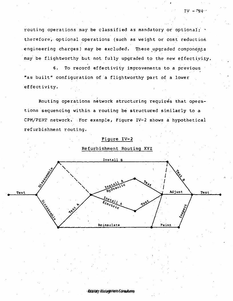
IV -^Sp-
ng operations may be classified as mandatory or optional; '•<
therefore, optional operations (such as weight or cost reduction
engineering charges) may be excluded. These tupgraded components
may be flightworthy but not fully upgraded to the new effectiyity,
6. To record effectivity improvements to a previous
"as built" configuration of a flightworthy part of a lower
effectivity. .
Routing operations network structuring requires that opera-
tions sequencing within a routing be structured similarly to a
CPM/PERT network. For example, Figure IV-2 shows a hypothetical
refurbishment routing.
Figure IV-2
Refurbishment Routing XYZ
Install B
Test

. . . I V - 5 5
This network operation structure for routings will facilitate
production control for the following activities:
1. Parallel work operations for one routing. These
could be WADs for different engineering operations which can be
performed at the same time on the same shop order routing.
2. Multiple paths of refurbishment operations routings
which disassemble components for parallel testing or rework in
back shop operations.
Preventive maintenance routings for GSE and buildup stands
require that these operations be recorded in the same form as
shop order routings and resource requirements identified. Part
master numbers would be reserved to facilitate scheduling control
(using the same method as production scheduling) and to facilitate
preventive maintenance cost tracking (part master value added
information).
Off-standard and nonproductive work tracking requires spe-
cial category part master numbers and dummy shop order routings.
Whenever unusual or nonstandard work (e.g., cleanup or idle time)
occurs, the time would be recorded against a special category
shop order. Actual time would be recorded against the dummy
shop order and value added recorded against the part number.
Monthly or periodic reporting would be able to record the occur-
rence and cost of these exceptions by category.
Exception operations for problem resolution or process
changes (e.g., TPS/PR/DRs) require the addition of an operation
Kearney: Management Consultants
IV - 56-v
to the shop order routing. This may also include the disassembly
and reinstallation of any component. Exception parts used would
be recorded against the shop order and exception resources used -
recorded against the routing operation of the shop order. Con-
figuration delta lists would highlight these exceptions to indus-
trial engineering which would be responsible for effecting any
WAD. changes or any manufacturing BOM changes necessary, and for
alerting design engineering of any engineering BOM changes
necessary.
(j) Configuration .Management
Summary Narrative. Configuration management is designed to
provide the capability to compare "as built" materials and work
performed to "as designed" materials and "as planned" work struc-
tures .
Comparisons of "as built" work performed versus "as planned"
work structures is currently conducted through the data pack
buy-off analysis. Within the automated production control en-
vironment for the SRB operations phase, this could be simplified.
The simplified data pack buy-off could be a comparison of the "as
planned" routing to the "as built" work performed. This automated
assist to data pack comparison could produce a delta list identi-
fying the following.
1* Routings with operations not having proper WAD buy
point authorizations.
Kearney; Management Consultants

IV - 57
2. Operations sequence changes and shop floor supervisor
inspector notes of reasons for the change.
3. Operations with alternative work centers arid shop
floor supervisor or inspector notes of reasons for the change.
4. Operations with alternative labor skill certifica-
tions used, and notes.
5. Operations with alternative special resources (e.g.,
supplies, tools, GSE and subcontractors) used, and notes.
6. Operations deleted and notes.
7. Operations added with cross-references to PRs, DRs,
or other exception WADs, and notes.
It should be noted that LRU dismantle and reinstallation
for any reason would require additional operations to be incorpo-
rated to the routing.
8. Standard time variance analysis for operation time
at a work center.
9. Standard time variance analysis for operation time
work by labor skill.
This data pack buy-off could be required to close a shop order;
therefore shop orders with no work remaining will be queued for a
buy-off decision.
Comparisons of "as built" materials versus "as designed" is
a comparison of the bill of materials for a part effectivity to
the actual materials used. This requires "as built" configuration
part information s;uch as: .
1. Part effectivity.
Kearney: Management Consultants
IV - 58
2. Part flightworthiness status.
3. Part life cycle history. .
4. Part source, (vendor) information.
5. Part serial number. ..- .
Materials configuration comparisons could generate materials
delta reports. These reports could be used for the following pur-
poses.
1. To assist in buy-off analysis.
2. To compare "as designed" configurations across
multiple effectivities. .
3. To compare "as designed" requirements to "as built"
configurations of spent major assemblies to be refurbished. This
analysis could identify components to be disassembled for design
modifications or life cycle reasons.
Effectivity management and life cycle management require that
configuration management have the capability to initiate the "as
built" data capture during the prerelease assignment of serialized
parts to a specific shop order.
For each manufactured and serialized part in inventory, an
"as built" configuration could be maintained. This configuration
should be readily accessible (e.g., on-line) to engineering, effec-
tivity management, life cycle management, quality assurance, and
production control.
It is, however, anticipated that the level of detailed
Kearney: Management Consultants

in forma t.-io:n- ma intalned, by.. the••-. -KPC sys.tem would not be; suf f icien't:
for NASA's current needs'.arid .tha.t if those specific needs continue,
ACMS or an equivalent would be necessary.
(k) Labor Control
Summary Narrative. Labor control is designed to track labor
applied to a shop order or other work categories.
This will faci l i tate productivity and cost,'analysis.. Some ,
labor productivity and cost analysis capabilities are:
1. Work task and worker standard time variance or
productivity analysis.
2. Worker uti l ization analysis (percentage of time
on standard work).
3. Labor department productivity analysis.
4. Department utilization.
5. SRB direct labor variance analysis.
6. Inventory labor value-added analysis.
7. Data collection to interface with PMS analysis.
Kearney: MArwgement Consultants

IV - 60
SUBSYSTEM - .OBJECTIVES -
The automated production control system is composed of thee >-•'
subsystems described in the previous section. Each of the six
key subsystems (highlighted in the System Overview Flowchart,
Figure IV-1) are further described in this section. The key
subsystem specifications which follow are intended to support and
further amplify the previous descriptions. Each of the subsystems
is described in the following manner:
1. Subsystem flowchart.
2. Key subsystem narrative.
3. Key input source definition and data elements.
4. Key output definitions and data elements.
Identification of data elements is limited to the name of the
data elements. More detailed descriptions of ;each data element,
such as field size and data type, are found in Section V, Computer
Systems Requirements. The numbers in the text correspond with
the accompanying subsystem flowchart.
(a) Master.Scheduling
The master scheduling subsystem defines a two-level master
production schedule. The first level defines the final assemblyi
(stacking) and check-out of the SRBs (KBAC Operations) based upon
launch schedules provided by NASA. The second level defines the• • t • ' • • •' •. '
major components (aft skirt, frustum, etc.) and parts kits requiredi
for aisle transfer .in order to meet the launch schedule (MBAC).
This subsystem "pegs" the two levels; i.e., traces the major
Kearney: Management Consultants -

' . IV - 61
component requirements back to the discrete stocking shop order
in order to maintain total SRB refurbishment/subassembly/stacking
schedule integrity.
1. Subsystem Narrative. The flowchart shown in Figureii
IV-3 indicates the primary subsystem logic. Launch schedules (1),
provided by NASA are used for two purposes. First, a single
level, time-phased explosion (2) of major components is developed
for KBAC, considering the estimated time required for each stacking
and check-out operation. The manufacturing bill of materials (3)
is used for this explosion. The result of this activity is a
time-phased major component, gross requirements schedule (4)
(not considering major components already in the system of MBAC).
Second, the launch schedule drives a refurbishment
schedule (5) which is the anticipated due date of refurbished
major components. This planning phase (6) is based on the
cycle times for recovery, cleaning and disassembling (KBAC), and
refurbishment and subassembly (MBAC).
Next a "netting" activity (7) takes place via an inven-
tory file (8) (on-hand and planned) where gross requirements are
compared to on-hand or planned inventory receipts in order to
determine if a refurbished component is available or planned to
be available (9). If.a refurbished major component is not
available or planned to be available, the subsystem will check
the availability of a new assembly (10). If a new assembly is
not available, a new build manufacturing order (11) will be created
for the assembly of the major component. If a new assembly is
Kearney: Management Consultants

Figure IV-3
Master Scheduling Subsystem
(5)
r LAUNCHSCHEDULE
REFURBISHMENTSCHEDULING
SINGLE LEVELTIME PHASEDEXPLOSION
GROSSREQUIREMENTSSRBMAJORASSEMBL
SCHEDULEMANUFACTURING
ORDERSETAs
NEW BUILDPRODUCTIONSCHEDULE
CHECKINVENTORY
AVAILABILITY
NEWASSEMBLYAVAILABLE
REFURBISHMENTASSEMBLYAVAILABLE
~l
i
-H
. ALLOCATEON-HAND
. PEG/RESCHEDULEMANUFACTURINGORDERS
i
. ALLOCATEON-HAND
. PEG/RESCHEDULEMANUFACTURINGORDERS
(15)
\ SUMMARY \1 RESOURCES I— »/ REQUIREMENTS /
I
••«•«•
(14)
GROSS CAPACITYPLANNING
OPERATIONSBUDGETING
CREATENEW BUILD
MANUFACTURINGORDERS
-1
• - • • /
\
MANUFACTURING /ORDERS /
. SRB6 f~
. MAJOR \L ASSEMBLY \
(17)GROSS CAPACITYEXCEPTIONS
. BY RESOURCE
.BY MONTH
(16)MASTER SCHEDULE. SRBs. MAJOR
ASSEMBLY„.
Kearney: ^Aarw^3ement Consultants

IV - 63
available, the subsystem will allocate (reserve) on-hand major
components and reschedule the open manufacturing orders (12)
in order to comply with the new assembly requirement.
If in the "netting" and inventory checking activity a
refurbished major component is available, it is reserved and re-
revised schedules are created to comply with the time require-
ment (13).
Based on requirements for refurbished components (13),
new components already available (12) and new components which
must be created (11), a gross capacity check is made (14). This
is accomplished by adding the time-phased requirements for key
resources (labor, materials, facilities, GSE, etc.) and comparing
these capacity requirements to a summary file of resources avail-
able (15) in order to determine if "gross capacities" have been
exceeded. If they have not been exceeded, the master schedule
is assumed to be acceptable and a "verified" master schedule is
created (16). If the preceding logic will not produce a verifiable
master schedule, an exception report (17) will be generated
indicating that gross capacity for a specific resource (e.g.,
Hot Fire Test Facility), is exceeded and that the launch
schedule (1) as defined cannot be met.
2. Key Input Source and Data Elements. Figure IV-4
shows a summary of the key inputs required for the Master Sched-
uling Subsystem.. The "topical reference" refers to the major
subsystem input indicated on the flowchart.
Table.IV-2 indicates the key data elements associated
. Kearney: Management Consultants

IV - 64
J3 C C•g i v01 E E 01tn 0) j= I-HW Li 0) 3< -i-i -0
3 J3 01LI cr LI jc.o o> 3 uT->OS iw to
£
01 EW OIW Ll<•*<LI tr0 01
a
41 -p<n jan ID
U 10o >
>i n-I CO Q>•0 Ea ai10 LI mO -i Jf
a u
m o> j=O K U
o
~* co ai0 1J10 LiU -• X
3 Oco cr 0)n v jco as ouO
E(U
to(0
3^f
1
M
d>acH.Ht,
W
CPc
•1-t1— 1b'O
r;0tn
(D
10
VjmE
DW
jjDacM
. "o0)u
cr01
•o0>Li
IOS
•O
b-H
§•
•D01
3cr
•D >4at uXI C
-< crxi oi0) Ll
IDXI10O C
oIU -HO xi
10LJ UO O
10
Llo
m to
-I 01b. OS
O Oo ofN fM
01Ll•H
IK
0)
01n
•Vb uO O09 01z oso o
•o.-B-H3
01
n
IaMX0) •O Li0 CnLi Ca. u
tn01 xico oi o
co •D«\. bxi m ojs -o ucr> b o
— o a-I Uu. oi o
K oo oo o *
•o0)
cro>OS
•oo>Li
3O1
a
a0)a
0)•o
n LJ•H o»H O•* 01BOS
o o
•o01Ll
er01OS
s
0
e «. ob •CO
1
ae ooo
Ll Li CO -H3 XI S X> CX) O I 10-IO 3 M i* jcID -a a 3 xi•M c w o -HC M D •-! toj 10
cID1-1o. >
CO
3 aO con a
m•oo
01 U3 JC 010 xi esto c01 o oos x o
CO0 0 -CO SO 9
•o01Ll
3cr£n
£ccaa >
coo> EU Ila *H3 ao con a&
o> 10u xiLl 103 Oo
CO IMo
a
Oi 01I-l XI i-lID 10-«3 «H U-lC —•0
Oc
01 Krl U
U10b
0> Ki-H U
0)i-l
lb
3•D01
Uc310
! C 0>
t> IM10 O
T->S: cc.18
I-i o
E >,"C -OOi Li C 0)0) O 10 CW XI = C< C I IB
01 C*H> o o-
01 -.u ^Li ^13 x> —Io c en o tr>IU E C 01es o)— u
Li C Ll>,-< C 3Li 3 « 0
E 0) ObE « —
co
in
uLi
Si,--01 •»< i-l01 -H -<c: -i jo
j2 10>i 10 -I
10 ~4 ID C6 10 > 10E > ra -i3 < —Ciu
Kearney: Management Consultants
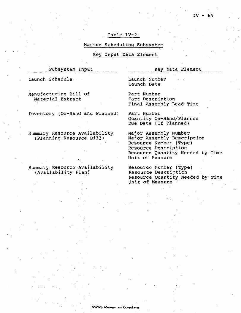
IV - 65
Table IV-2
Master Scheduling Subsystem
Key Input Data Element
Subsystem Input Key Data Element
Launch Schedule
Manufacturing Bill ofMaterial Extract
Inventory (On-Hand and Planned)
Summary Resource Availability(Planning Resource Bill)
Summary Resource Availability(Availability Plan)
Launch NumberLaunch Date
Part Number .Part DescriptionFinal Assembly Lead Time
Part NumberQuantity On-Hand/PlannedDue Date (If Planned)
Major Assembly NumberMajor Assembly DescriptionResource Number (Type)Resource DescriptionResource Quantity Needed by TimeUnit of Measure
Resource Number (Type)Resource DescriptionResource Quantity Needed by TimeUnit of Measure
Kearney: Management Consultants

. . . : .IV"- 6 6
with e.ach of the inputs identified.
3. Key Output Definitions and Data Elements. Figure
IV-5 shows a summary of the key outputs provided toy the Master
Scheduling Subsystem. The "subsystem output" reference refers* . '
to either a report, CRT screen, file update or a comb i-rtati-on of
the three.
Table IV-3 indicates the key data elements .associated
with the subsystem output.
Kearney: Management Consultants
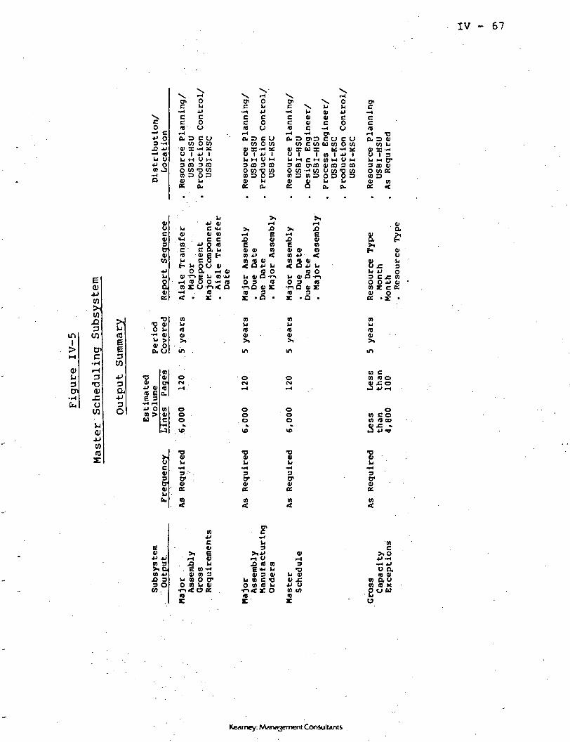
IV - 67
\e0
"•"* £Jxi 03 -H•O *-< mLi Uxi oCO 0
— cO
C CC 010 U
<-<a 3 c u
w o wa> z: ~i :•;U 1 xi 1Li M U l-l3 CO 3 COo w *o wW D O 001 Lia ft.
x ^n\ yC Li-I J->c cc offl C>
ft, D C OW O W
- I *J Ilj )H O M
3 m 3 ffio wo wCO D 5 D
^n ^^ OC \ Li U
••4 Li gj xlC 01 01 CC 01 C O
(L O CO C O C OW C W U W O W
u s: u x *fi~* sfiu i i n I x> ik J > H C ' - ' C O > - l U l - l3 CD U* CD 0) CO 3 COO W "* W O W ' D Wm o m o o o o o4) Jl Li Lia: a a. ft.
ec<0-i -Dft. 3 0)
W Li
83 CO 01owe:CO D01 COet <
inI
(D
3
V)
W
3
CPc•H
a>J=u
0)
c013trOlto
£:01OS
CO. C '
10
XI 01C <uoi nc c
S8.180>c
Li CO'.
*§
e3
CO
3O
^ >01 Oa u
Hjj 0110 E6 3
••* iHtJ OCO >U
f« Li 00 0)o a r-t oi
0) Tl g U•H <0 O O 'co r u-i-i-i «< • r
COu10Ol
o(N
ooo
>, ^M EE »01 0) COco xi <co a oi< a xi u
« OU 01 D -r->OS <0f->O 01 £a 3
CO
0)
in
Ooo
<-< EJ3 <DE cooi oi coco xi <CO m Ol< a xi LI
ffl oLi Ol O -r-iO 3 10
•1-1 O 0> X10 3c • a •
m
O)
m
o(N
OOo
£8
Li x» o3 C £ V)O O XI 41CO £ C K
1001
10 cM 10 O01 £ O
O0) COCO (0 GO01 £ «iJ *J V
10m
41
O-
£u.
•D0)
I"CO
3tr01ccm
•D01
3D1
3crai
co
o>•u *jn 3x cunJ3 33 O
njjc0>
>i Erl «J5 ^
. E 0>~<oi m 3
u co o cro m u oi•n« ca K
M ujo a na> 3 oi
u » c -oO 0) (B Ui->< r o(0
4> JCXI OCO CO10
u am 0)
o) auco a xo o w
Kearney: Man^jement ConsultAnts
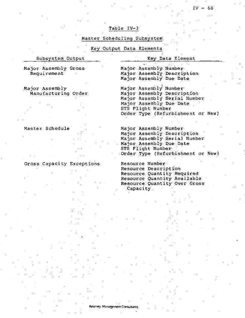
IV - 6,8;
Table IV-3
Master Scheduling Subsystem'.
Key Output Data. Elements
Subsystem Output
Major Assembly Gross.Requirement
Major AssemblyManufacturing Order
Key Data Element
Ma^jor Assembly NumberMa jar Assembly Description-Major Assembly'' Due- Date;
Major Assembly NumberM'ajor Assembly DescriptionMajor Assembly Serial NumberMajor Assembly Due DateSTS Flight NumberOrder Type (Refurbishment or New)'
Master Schedule
Gross Capacity Exceptions
Major Assembly NumberMajor Assembly DescriptionMajor Assembly Serial NumberMajor Assembly Due DateSTS Flight Numbe.rOrder Type (Refurbishment or New);
Resource NumberResource DescriptIon-Resource Quantity RequiredResource Quantity AvailableResource. Quantity Over Gross
Capacity
Kearney: Management Consultants
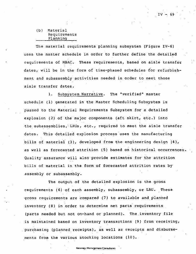
IV - 69
(b) MaterialRequirementsPlanning
The material requirements planning subsystem (Figure IV-6)
uses the master schedule in order to further define the detailed
requirements of MBAC. These requirements, based on aisle transfer
dates, will be in the form of time^-phased schedules for refurbish-
ment and subassembly activities needed in order to meet those
aisle transfer dates.
1. Subsystem Narrative. The "verified" master
schedule (1) generated in the Master Scheduling Subsystem is
passed to the Material Requirements Subsystem for a detailed
explosion (2) of the major components (aft skirt, etc.) into
the subassemblies, LRUs, etc., required to meet the aisle transfer
dates. This detailed explosion process uses the manufacturing
bills of material (3), developed from the engineering design (4),
as well as forecasted attrition (5) based on historical occurrences
Quality assurance will also provide estimates for the attrition
bills of material in the form of forecasted attrition rates by
assembly or subassembly.
The output of the detailed explosion is the gross
requirements (6) of each assembly, subassembly, or LRU. These
gross requirements are compared (7) to available and planned
inventory (8) in order to determine net parts requirements
(parts needed but not on-hand or planned). The.inventory file
is maintained based on inventory transactions (9) from receiving,
purchasing (planned receipts), as well as receipts and disburse-
ments from the various stocking locations (10).
Kearney: Management Consultants

IV - 70
Z C
in uiw <CD t->tx u3 «•b. OU b.a
§
ast«<
«•g
g KU
M U
Q U
VO
<D
cn•H
W>i(0
JD3
cnC
•HCc(0rH
COJJC0)
(U
3a1
CO
a>4J(0
INV
EN
TO
RY
PO
LIC
Y
Ul
or S
IZES
^PE
TY
ST
OC
K
3 M
»
INV
EN
TO
RY
RA
NSA
CTI
ON
S
^ ^ 1
H
O — -
OF
AC
TU
RIN
GPU
RC
HA
SEO
RD
ER
S
ii
XB
8£
Kearney: Management Consultants

IV - 71
Inventory policies (11) relating to such things as safety stocks,
etc., are also used.
In addition to the net requirements being provided by
the inventory netting calculation, planned orders, rescheduled
firm orders, released orders, requests for purchase orders and
expedite reports are also generated.
2. Key Input Sources and Data Elements. Figure IV-7
shows a summary of the key inputs required for the Material
Requirements Planning Subsystem. The "topical reference" refers
to the major subsystem input indicated on the flowchart.
Table. IV-4 indicates the key data elements associated
with each of the inputs identified.
3. Key Output Definitions and Data Elements. Figure
IV-8 shows a summary of the key outputs provided by the Material
Requirements Planning Subsystem. The "subsystem output" reference
refers to either a report, CRT screen, file update or a combination
of the three.
Table IV-5 indicates the key data elements associated
with the subsystem output.
Kearney: MAr»3ement Consultants
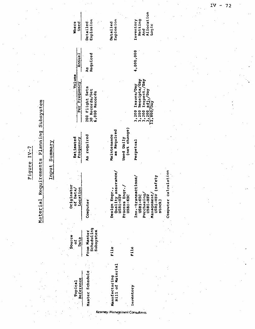
IV - 72
U Cl01 CO
• cro o0> -••H 0>-* o« --ttt)a O
C0•**B)0*-laU
CO
X enh/ cO ~*4J JJ OC i) TJ -HO 4) C ^> Z < <
10O O
4JW
W
aW
ccus
wc(U
<1>
3crw
(D
<D
s:
VE3^H
O
^
•H103CCi£
•DVU
'i*4
3•IT
W V< K
0c0>3D"01hib.
hi0*(X
CDAJ 4J41 4) 05
CO M "UX lJ
iJ 01 Oj: *o y
CT hi Of
— O «^ Ob. 01 O
K 00 Oo o •
. cs o ve
ooo
••ooo
(0
E3
3CuC
•D >8) U*» Ca a>E 3•H. trjj a>a iju b.
•DO>
3ITO>U
CO
OX C*» 1C Oa 4J *<c «i *J•^ Q <o<P U
<^4 IU Ob O JO
•o o>a* o>
O> hi CO •** >-i 10C 3 »H C.
S tr -^ o0< <0
4J «C (0 'DC•^ a v —IB 0}X S
a>u
310
0)a
«30)
cw
fc ou coCO I
e r-« •* B M-< 3 CO O COo) a o o oC) ^
X
aO
O<8
c co c u .c ton us -H s 01 = -»u i tn i E i j^jj M (0 M 4i •«-! Oi ffi j: to erica o• CO U CO 10 CO 4J>=> u a c 3 mc 3 ieM a. i
co
3O
IBO
ao
U 10U IM 4J3 O «o aw
.n c E41-^ 01*• - JJa 3 »« -o >.X o> o:
JC ^J6 0 3O CO CO
•0)rHM*
Cu
01-I O« cO 0>•^ uC. 0)O ^M
3•O0>
'CO
u014Jn
hi0>
C 10-4 X•hi3 >"•u O
3 -^c ecHi
Kearney: Artarwvjerhen't ConsulMnis

IV - 73
Table IV-4
Material Requirements Planning Subsystem
Key Input Data
Subsystem Input Key Data Element
Master Schedule
Manufacturing Bill of Material
Inventory
Major Assembly NumberMajor Assembly DescriptionMajor Assembly Serial NumberMajor Assembly Due DateSTS Flight NumberOrder Type (Refurb or New)
Parent Part NumberComponent Part NumberQuantity UsedUnit of MeasureEffectivity (STS Numbers)Engr. Change NumberEngr. Change DateDrawing NumberFind Number
Part NumberPart DescriptionEffectivityClass CodeABC CodeSource CodeUnit of MeasureInventory Account NumberReorder PointReorder Policy DataLast E.G. Change NumberQuantity on HoldSafety StockPart Status
Kearney: Marwgement Consultants
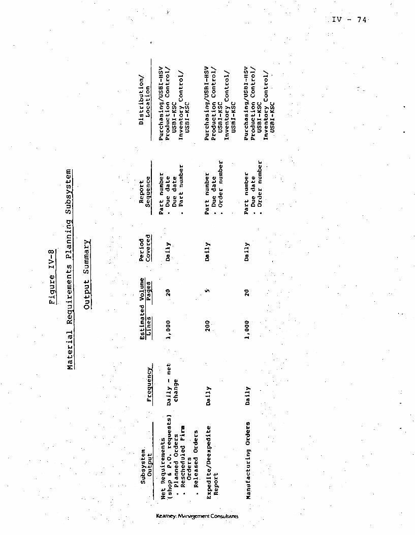
.IV - 74
eo*j o3-H
JO *J•r< IBU Uu Oto J
> XCO -1 Xso »-i
•0 cCO 0=> u
ohiu
ou
o oC 0 CO
B -U I O I
JC 3 a C C3O "O tO ft) WU 0 D > 33 Lr CQy ft. M
een
rHou
oD O
0ueo
cr> c u ucow >ico
—«•-< se u *:n j-> i o iIB y M jj 1-1£ 3 a C Ku -o w o> cob o a > D2£ £
35-> x= O rH •I b Ol-l JJ Ua c jjco o cD u oX UPI C O CJC O CO >iCQ
•H -^ ^£ b K« *J I 0 Inj o i-i JJ Mjc 3 m c ecO •O CO 41 Wu o o > a? u e
CO4JCO
CO
3CO
01U UU C
S.301 CT(6 0>
CO
u01
U JD01 0> 01 EjD 4J ii 3£ IB 10 C3-0-0C -U
Q) Q) VJJ 3 3 «b O O O,>0
U01
U EV 01 3JO JJ C
g -o IHC 0>
Q) -g*» 3 UU Q OIBa. . .
00I
0)^3
CCm
cojjc0)
<u•rH
3
crOJ«
(0
•o o>O b-H o>U >
£8
0)E3,•40>•o01
10E
••*
Uu
0)0101IDft,
v>cJ
&
ofN
OOo
&
oo
&
o<N
Ooo
0)
(8£ 0)
cI 0)
o>>l C-( It•H or
eJJ 3in arS JW 3
JO O'3CO
M
. C01g01
^4• 3
tro>C£
i
toIf
M
§
f
»
O•a,
<0aon
inu01
T3UO
•O0)ce10rHa,
•
s•HGb
J3 W•C b01 01J=-0u uui o0)a•
M
&>
1
•C01091001rH0>K
•
3
KO>O>QX01
T< U
•o oo> aOi A)If KU
2s
3JJO .
3C.10£
Kearney: Marwvjement Consultants

IV - 75
Table IV-5
Material Requirements Planning Subsystem
Key Output Data Elements
Subsystem Output
Net Requirements
Key Data Element
Expedite Report
Manufacturing Orders
Part Number/Serial NumberPart DescriptionQuantity Required by DateQuantity Required by
Requirement NumberQuantity Allocated by
Requirement NumberPlanned Receipt DatePlanned Receipt QuantityOrder Status (planned, firm,
released)Order NumberLaunch Number
Part Number/Serial NumberPart DescriptionQuantity Required by DateQuantity Required by
Requirement NumberQuantity Allocated by
Requirement NumberPlanned Receipt DatePlanned Receipt QuantityOrder Status (planned, firm,released)
Order NumberLaunch Number
Part Number/EffectivityPlanned QuantityDue DateStart DateLaunch NumberNext Higher Assembly
Kearney: Management Consultants

IV - 76
* ' .
(c) CapacityRequirementPlanning ~"•" -
The capacity requirements planning subsystem (Figure IV-9)
provides the information necessary to identify capacity constraint
overloads and help management resolve such conflicts. Capacities
for key resources are loaded based on schedule requirements and
overloads are noted by resource. Resources include work centers,
labor certification, GSE unique to USBI, and major tools. When
overloads are identified, the overloaded resource will be noted,
in addition to all the activities, by operation number, contribu-
ting to that overload.
1. Subsystem Narrative. Manufacturing orders (1) from
the Material Requirements Planning Subsystem will be passed to
this subsystem. Routing data (2) are combined in an activity
which translates manufacturing orders into shop orders (3) by
operation times and resource needs. This translation is then
used to develop a detailed schedule (4) through the incorporation
of GSE preventive maintenance process documents (5) exception
process documents (e.g., TPSs, PR/DRs, etc.) (6), as well as
process constraints (7).
Detailed schedules are then converted to load summa-
ries (8) by using work center capacities (9) and resource skill
capacities (10) in order to provide capacity load reports (11),
labor load reports (12), and resource requirements reports (13).
These reports, which include capacities of each resource (e .g.,
work centers, etc.) will be used by management (14) to determine
Kearney: Management Consultants

IV - 77
Figure IV-9
Capacity Requirements Planning Subsystem
NETREQUIREMENTS
HANUrACTURINCORDERS,
TRANSLATERANUrACTORlNGORDERS INTOI BOP ORDERS
OPERATIONS TIMINGRESOURCE AND(KILL HEEDS
PROCESSDOCUMENTS
MAD*WSOUKCE *KDSKILL NEEDS
L
(4)
DETAILEDSCHEDULING
(BACK SCHEDULING)
P.H.PROCESSDOCUMENTS
(5)
( E X C E P T I O N 7PROCESS /
DOCUMENTS j ,
. TPS V
. PR/PR \
PROCESSCONSTRAINTS (7)
(I)
LOAD(UHHAKIIATION
1111MORK CENTER
CAPACITY LOADREPORTS ANDRESCHEDULING
RECOMMENDATIONS
MORK CENTERCAPACITIES (9)
RESOURCEAND SKILLCAPACITIES
(10)
(12) (13)
LABOR SKILL
(14)
COMPARELOAD TOAVAILABLECAPACITY
(17)
Kearney: Management Consultants

• • • ' : • I V - 7 8
if major or minor rescheduling is required. If minor reschedul-
ing is required, manual changes (15) to the detailed schedule are
input. If, however, major rescheduling is required, management
will have to make changes to the master schedule (16).
If rescheduling is not needed due to capacity overloads,
detailed production schedules (17).can then be released.
2. Key Input Sources and Data Elements. Figure IV-10
shows a summary of the key inputs required for, the CapacityD
Requirements Planning Subsystem. The "topical reference" refers
to the major subsystem input indicated on the flowchart.
Table IV-6 indicates the key data elements associated
with each of the inputs identified.
3. Key Output Definitions and .Data Elements.
Figure IV-11 shows a summary of the key outputs provided by the
Capacity Requirements Planning Subsystem. The "subsystem output"
reference refers to either a report, CRT screen/ file update/ or
a combination of the three.
Table IV-7 indicates the key data elements associated
with the subsystem output.
Kearney: Marwvjemeni Consultants

C T)LJ ou tna o
E(D
W
COJQDW
eo
U XI3 IB
U Li U10 01 C
«J -o IB3 Li UC O H
•oV
Li01
Ll3
001
' CO 00. *D
03 ~ C O >jxi a -< o <B£ £ XI xl 01 Qt»xi 3 j: K
•H e o PI LI—i O a:-i « oib, E -* K a
« b. OO Vf> X CM tf(s •—•• ' • in
« 4> C«M *D a3 Li LiC O f *IB
•D01
w4EO
m **
O
09•OLi
v. 809 01D* >*CC
XI -( —i X B£ 09 xl > IB QWin 3 -H X•H X O x» Li.H O K O» 01b, oi K a
i J • tJ
O O X tu O «•CM co • u <M in
•D 30> *O
~* 01
IB Uxl CO
01
••4
LJo
•O 3
-I 01*v* £0 U
£
ooCD
•D 3.0) TJ•H 0)•»* £« Uxl IA
•O
e••«
Lj01
•C 3& ^3""I OI•** JCQ Oxi (0
•D01c~euoi
•O 301 TJ
IB Uxi toO
' O
•O«
Lj01
£
(DM
0)
a 3oSoin —i
_ >i « *JU « XI 09OQ .ex,u a> LI01 Li " 01a v -c a
a b.o oo o» o om m fs «N
to•o >iLl 100 ou01 hiK 01
aino»
0) PIffl c0) xi
II
0>m a03 "D 01 >,Li 0) D.H0> C >,\ 09X>— O 09 «0C E 01 L.0) Li 0> U Ot) 01 O Li U Si
XI Li 3 Oi *).My s o K oLl C O 09O O) 0) « LjX 01 01 Om X 01
ffl a « ao *O O O M O *«H t" CO • CD in
oI
0)uaCp
cCTO
U)+JC0)
VK
u(0a
•o >JOi OJJ C
E 3
xl oi09 LlU b.
•OVu3'er
A; u 09oi o «
LIox. cXI IB O•8 xi -HC * xl-* O <0
«4 <u QU O JO
•o01
Ll «01 LJxl oi3 C
10o
X
UI
•o01u
••H
o-01K
•* 09•* ns
•D0)Li
crvu
5
•D01Li
3cr£
•O 'a>Li
3cr01Li
CO
C CO
09 I09 fOf CQU (0o oua
i01uc
0) «JU> c w-I O/ *xl xl IC C M0) —• eo> * toO X DLla
uU U
8 io c cok: -i ae
tH I 0) Iiw t-l 09 «-i
a oi eCLCO U COO D O OJC LJco a.
u u
c co09 I09 «H01 03o coo sLia.
c coa ia 1-1O CO
8 =fi.
coIP>CJC CQ-H K09 I09 IH01 CDu co2°a
O 4
§°s(0
^ e tn oio o> c .u•— LJ^ nLI — C X0) 3 C 10M era e « oi •-! 3o x ce a. w
LiCv
01•H•Hb.
01l-l•W4b.
0rH•«4fiu
01i-l•EL
01•*•HCw
01•H U« cu «-< Li
LI :3•u mU Ll
• oi»"03 LiC O<0X
X)
OK
a>-- ux) CC.«Boi c n> 01 -Uoi xi m cLI e n oo, -— » E
( 0 0 3u x oCO Ll
090901
0LiB. 0)
c cO CJ-H EXI 3a u0) Oo ou
C 09—• XI
. c e. Li 010) xi E0) 09 301 C UU O O000Li
0)Li 0101 -HXl XIC -iOi Uo <o
aJ< IBLi L)o
•cc
09Oi
01 —O -I OLl ~4 «3-. a0 M <BB U U
£
Kearney: Management ConsuttAnts

IV - 80
Table IV-6
Capacity Requirements .Planning Subsystem
Key Input Data Elements
Subsystem Input
Manufacturing Orders
Routings
GSE Preventive MaintenanceProcess Documents
Exception Process Documents
Process Constraints
Work Center Capacities
Resource and Skill Capacities
Key Data . E.ljement
Part Nurhber/EffectivityPlanne'd QuantityDue DateStart DateLaunch NumberNext Higher Assembly
Fill from CSR Sheet
Fill from CSR Sheetsfor Routing without Setup
Fill from CSR Sheetsfor Routing without Setup
Part Number/Routing NumberOperation CodeNetwork Structure Code
See CSR Sheet for WCC
Resource NumberResource DescriptionSame as WCC from CSR
Kearney: Management Consultants

.IV - 81
rib
uti
on
ati
on
» o
S0uc uo in
Pro
du
ct
US
BI-
o
oue uO W
Pro
du
ct
US
BI-
0
Ic u0 W
Pro
du
ct
US
BI-
O
0
c uo w
Pro
du
ct
US
BI-
0
ocjc uO (0
Pro
du
ct
US
BI-
o
0
c o0 en
Pro
du
ct
US
BI-
S
o0
c uO M
Pro
du
ct
US
BI-
'Co
c uO (A
U «3 03•D WO DLiOu
M
0)
(b
0)
(0
.03W
cc(0
to4Jc(U
0)
3cro>«
3cn
3a3O
4JLi
C01
a cr01 0>ce en
Li01
JJ CC 0101 (JEjj >;Ll Ll
Li0>
CC 0101 U
u U
au c•H o
LI ao g•u ttm CdO
c uS u5 oLl JO(0 IBaO
J I Jg*C (A0>
3 O
8,3
01oo
o(N
O I
o§s au
« ou KU
ooo
Oo
a LIa oLIo
mu
LI ao g
0) Uo
&01uLi u3 01 "•O JO 3
3 w E crO 01 3 01O tt Z «01
•D
•gs^ 0)u >01 Od.0
tt£JJco£
VO
mXjjco£
VD
COX4JC0X
\o
01£*>cocve
wf.4JCozvo
10£JJCocve
0)JCjjcoa:«e
o<N
a8KU
X CLl O01 —4
Li (0O Li
at18-u
co
oo
ooo(N
u(0Du(0U
°STxce
01
•o01LI
•f^Ll 3
•aoLI-*^Ll 3o cro>
•o0>Li
-*4Ll 3O cr
OI
X 0)01 <0V
ma
M 0)01 K)
0<4J 4Jn 3xan ^£ 3•a Ou
to m
e0)
v m8 L| 4J
-H Ll
Ll 3 Os cr a
cO lit
-H 01JJ —I
• D O S£ 3 T5i-« "D 0)•- 0 JC(0 Li O*• Ou W
Kearney: Management Consultants

IV - 82
Table. IV-7
Capacity Requirements Planning Subsystem
Key Output Data Elements
Subsystem Output
Work Center Capacity LoadReports and RescheduleRecommendations
Key Data Element
Labor Skill Loads
Resource RequirementsReports
Detailed ProductionSchedules
Work Center DepartmentWork Center NumberWork Center DescriptionWork Center CapacityWork Center LoadTime Period ;
Labor DepartmentLabor Skill Certification CodeLabor Skill Certification
DescriptionLabor Skill Certification CapacityLabour Skill Certification LoadTime Period
Resource GroupResource CodeResource DescriptionResource Requirement TimeTime Period
Shop Order NumberPart/Effectivity/Serial NumberOperationOperation Start DateOperation Due DateQuantityResources
Kearney: MArwgement Consultants

IV - 83
(d) Shop FloorManagement
The shop floor management subsystem (Figure IV-12) has two
primary functions. First, is the preverification of all resources
needed for completion of a shop order. These resources include
material and parts, labor, GSE and tools, etc. This is the final
check for "floor availability" before a shop order is released.
Second/ the subsystem actually releases the shop orders to
the work control stations for subsequent release to the work cen-
ters, along with other paperwork from the word processing center,
such as OMIs, BOSs, etc.
1. Subsystem Narrative. Detailed production
schedules (1) from the Capacity Requirements Planning Subsystem
are passed to this subsystem where inventory data (2) and resource
schedule information (3) are combined to provide a final check (4)
of "floor availability". The logic provides for a material on-hand
verification (5) where if material is not physically available, a
material expedite (6) is created and the shop order is placed
"on hold" (7). If material is available, a check is then made for
the current availability of other resources (8) such as labor by
certification, GSE by hours, etc. If any of these resources are
not available, a resource expedite (9) is created and the shop order
is placed on hold (7). Shop orders that are placed on hold due
to material or resource shortages must be manually rescheduled (10)
when the nonavailable item becomes available. If all material
and resources .are found to be available, shop orders are created
Kearney: Management Consultants

IV - 84
Figure IV--12
Shop Floor Management Subsystem
INVENTORY IRESOURCESCHEDULES
EXPEDITEMATERIALS
. . , (.9).
EXPEDITERESOURCE
COMMITMENTS
DETAILEDPRODUCTIONSCHEDULE
PRERELEASEVERIFICATIONS
DAILYDISPATCHSCHEDULE
MASTER^*SCHEDULECHANGENEEDED
47,)'
HOLD SHOPORDER
(10)
MANUALLYRESCHEDULE
INVENTORY
YES.. .
Kearney: Management Consultants

" , IV - 85
at the work control stations along with a daily dispatch
schedule (11).
A dispatch package (12) will be provided along with
material (13) and resource requisitions (14). Labor may then be
assigned (15), GSE and other resources (16) may then be acquired
and parts kitting (17) may then be accomplished.
A final check (18) is made prior to the actual start of
work to make sure that all requirements are "in hand".
2. Key Input Source and Data Elements. Figure IV-13
shows a summary of the key inputs required for the Shop Floor
Management Subsystem. The "topical reference" refers to the major
subsystem input indicated on the flowchart. .
Table IV-8 indicates the key data elements associated
with each of the inputs identified.
3. Key Output Definitions and Data Elements. Figure
IV-14 shows a summary of the key outputs provided by the Shop
Floor Management Subsystem. The "subsystem output" reference
refers to either a report, CRT screen, file update, or a combination
of the three.
Table IV-9 indicates the key data elements associated
with the subsystem output.
KeArney: Management Consultants

0)C110
s.en
O
•orexc .O <o tc
a oim oj -H jj•H ~< 3 M* o "o —i-i 01 >JLI >,j=o» rH y j*jj •* w y10 10 •*<r o a.
(Ajjc oioi t7»E <o•H y
f <0a m
o cO JS Oy —iO> JJ 01 JJy IB y ~iLi Q. Ll 103 ,» 3 "HO— O 3CO O CO C*0) 01 01« 05 a
IV - 86
•oo
*GLi
•O•01c
101
01 JJB 01
O
•ac
~fiOI
£
4Jto10
3CO.
J>,
ycOi
0) 3e o-3 0)
O fib,>
Li01a
m01jjc0)u
•£o20o•H
COCo•HJJ
201
£o<N
0)30130
J3
y10uc
•«H
CO•ooy£ooo«
CN
•D01
01 *JCO 01c
COLlOJJ CO(0 01tj y
§sino oO 05o-0
«N ^
CD
JJ Ll«0 Ou yS.S°0Ll O0) OCL *•
OCM
I
3cn
•HCLI
0)cnmc
oo•HPu
a,-c'cn
- D Ma> U
<9 V6 3
3ac
3
a3
*-
LlO \ CJJ (0 O10 JJ -HC ro JJ-• D 10tr> y
•H (U OLi 0 Jo
oa> LIC 1 JJ
•O . 10 C01 JC Li O Ujj y oi o w
0) Li 10 O CO 1JJ 0> CL CM3 c co •a o tna oi — < c •- wE U Q fl JJ DoCJ
a<M U
• J3 WX (0 ftfiJJ iH 1O **^ M
<0 CO• > cn> ft Sc
.M
10o
•o01JJ
Li (001 LlJJ 013 Ca oir
41 <0y JJu <o
(A «•<
0»iH•ftCu
Vi-t
« Cy 01
a 41O <*J
. Jo,JJ r-l
•O O 301 3 -Oi-l »O 01-• O J=<0 Li y•w o. w
c0>
c
01 3u •oh 013 JSo y« to
Kearney; AAarwgenoent Consultants
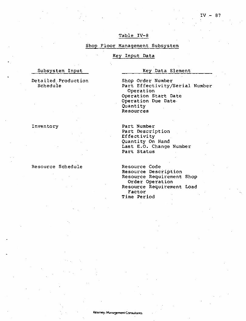
IV - 87
Table IV-8
Shop Floor Management Subsystem
Key Input Data
Subsystem Input
Detailed( ProductionSchedule
Key Data Element
Shop Order NumberPart Effectivity/Serial NumberOperation
Operation Start DateOperation Due DateQuantityResources
Inventory Part NumberPart DescriptionEffectivityQuantity On HandLast E.O. Change NumberPart Status
Resource Schedule Resource CodeResource DescriptionResource Requirement ShopOrder Operation
Resource Requirement LoadFactor
Time Period
Kearney: Management Consultants

IV - 88
cc-» c•" o3 -^£t. -u-. 10v y•" <2on J
Q
Uin
ffl
«C r-f
O O—1 LiJJ 4-110 eu oo-uao
uCO
aCO
inc r->o o—< u4J 4J10 Cu o41 Uao
(8 -I
oou
•r4JJ O W U
>, «8 co c wU O1 !< O *o o> i -* i4J U w AJ »r*C. IT CQ <0 ffl0> 4) C/J Li CO-> CO 3 4) Pe a.
II
ci•u yL. c£3c ol« o
CO
cLi O 0>oj x.-* yl; L. aJ CLi O 10 0)O -O Li 3e a) a-c. 3 a a>O 2 O CO
ui
X. 0)D.T33 OO Ou0 0)
y01 Liy 3LI o3 inO 0)to av(X
01yc0)
\ 3Li o>0) 0)
•D COLlO X
y
o a
GOVi3
WJ3D
CO
6OJC7^(CCCO
oo
a
-en
me
4JaCb4-J3o
T3•c oO U
— < CJLi >o oa. u
jo:fen
!a•C fc01 0>ij e
>-,20>co
ooo*H
** cH 36 -<
— o i o•J > o: o<r o
" H
SMycC3cr0)LIt_
o
o•— 1
o
•co
o) n0 Q
V>•.-*
— < 01-4 er
1Co
jj
8i-HCv
a0JCCO
20)co
ooin
oom
0•O O0) ^n in u.
10 10a> a
XrH O
•-( 01 £-i K CO
2
s01
ooo
opCO
13 001 ^
to en u.ID 1)ai a>i^ O^H 0) J=--< K CO
3 OCO
y <o•u x10 ye. 10tr, a.
teco
at my —iLi 3a tro o>m «o
10c
*H n10 -
-< 3LI a1
o> o>•u K.10i:
Kearney: Marvvjement Consuliants

IV - 89
Table IV-9
Shop Floor Management Subsystem
Key Output Data Elements
Subsystem Output
Dispatch Packages
Resource Requisitions
Key Data Element
Shop Order NumberPart Number/Effectivity/Serial Number
Part DescriptionOperations CodeOperations DescriptionOperations Start TimeOperations Due DateWAD Cross-ReferenceDrawing Cross-ReferenceWork Center InformationLabor TicketsResource InformationPicking List Cross-ReferencePrevious OperationsParallel OperationsSucceeding Operations
Resource CodeResource DescriptionShop OrderOperations CodeOperations DescriptionResource Delivery Time/DateResource Time RequiredResource Return Time/Date
Material Requisitions Shop Order (parent part)Pick List Release CodePart/Effectivity/StatusSerial NumberStorage LocationQuantityPart Find Cross-ReferenceNumber on Parent Drawing
Kearney: Marwvjement Consultants

(e) Operations Control •
The primary functions of the Operations Contrql Subsystem
(Figure IV-15) are to.track the resources expended to. a shop p.r-der,
including labor, material and parts, GSE and tools, etc., and tp
track the status of open shop orders.
1. Subsystem Narrative; A dispatch package (1) from
the Shop Floor Management Subsystem is passed to this subsystem.
All resources utilized, including materials (2) labor (3), and
other resources (4), as well as exception materials issued (5)
and exception processes and rework, are logged against the shop
orders (7). This provides information to update ghpp order sta-
tus (8) and to compare actual activity and resource usage to
the production schedule (9).
There are two outputs of this comparison, shop order
status reports (10) and exception reports (11). The exception,
reports provide management with summary information pn resource
usage variances, and overdue operations. If management dpes not
see a need for schedule changes (12), the exception reports that
have been issued are logged in as shop order w-prk activity. If,
hpwever, it is determined that rescheduling is necessary (13.), the
degree of impact (14) on the detailed production schedule (15), the
master schedule (16), and/or the launch schedule (17) need to be
determined. Thus, rescheduling can range from a manual adjustment
of shop floor priorities or a revision in the target dates in the
automated production control' system, depending pn the ne.e.ds seen
by management.
.Kearney: A/Urwvjement Consultants

IV -.91
Figure IV-15
Operations Control Subsystem
CURRENT ACTIVITY DATA FILES
(2)
(7)
LOG WORKACTIVITYTO SHOPORDERS
I
VMATERIALSRELEASED
(8)
UPDATESHOP ORDERSTATUS
(11)EXPEDITE NOTICES 1
(LATE OPERATIONS )l STATUSREPORTS
(13)
DETERMINERESCHEDULING
NEEDS
(4)
RESOURCEUSAGE
(6)
EXCEPTIONPROCESSESAND REWORK
(9 )
( DETAILED /PRODUCTION I
SCHEDULE V
(10)
(5)
EXCEPTIONMATERIAL
ISSUED I(3 )
LABOR REPOR'
TIMESKILLOPERA'
P O R T S f
.TION \
(17)
Kearney: Management Consultants
IV - 92
2. Key Input Source and Data Elements. Figure IV-16
shows a summary of the key inputs required for the Operations
Control Subsystem. The "topical reference" refers to the major "
subsystem input indicated on the flow chart.t
Table IV-10 indicates the key data elements associated
with each of the inputs identified.
3. .Key Output Definitions and Data Elements*
Figure IV-17 shows a summary of the key outputs provided by the
Operations Control Subsystem. The "subsystem output" reference
refers to either a report, CRT screen, file update, or a combina-
tion of the three.
Table IV-11 indicates the key data elements associated}
with the subsystem output.
Kearney: Management Consultants

IV - 93
ea>wW
tot— I
1!>M
0)Vt30~>
••-it,
W
•Ho^14-1couWcO
••HJl
4— 'a)
0)a,o
>(0E
3C/3
j_>3CucM
o>uA)W
*
01E3
#-4
O
^
•co>*J
E
0)u
LiO \4J 1Q1C AJ
^ ffi- S-»* vuiLi OO
4)yU Uj3 OOto
^M<Q
U•*4
aoE-
•DO>
3
<03CC
<
>iyc0)3CT01Li
CL,
u
01a
..ycOJ3crLl(L.
c01 1
10U
i_3
aJJ
10a
o>yc01Li01U-l
0)OS
to uC -( ViO O *
(0 C ECLi O Wai u oa0
•04)C
ELi0)
41 jj0 0)
C
0101C7*10aooo
I-H
>,,_!
v4
3
CPc u
— < wjr *:y i10 ea in01 O.*40
jjC £01 O>
Cu E ^O ft> o;J= Li O> >,w o re 01
O C.jQe -i 10 3o u. z u)Lltu
0!01
J^ CT*y rajj j^10 ya 1001 0..,-«a
010) Cy •** uc LI inP X* f
O c touj O 00L. S 3o>
•D0>C
E. Li
414) JJ
CD 01
01•cLi0ya>
ooCO
(N
'-'
>^,_<.v4
s
oLi "o ^O l-i 1
c c aoi O in> 0 3c
01coJJ
>i yLi IBO 0)*J Cc >oOi Li> E-ic•-1
•D01
—< W10 10
- CJLi — I0* 01*•* C£10r
cr>Oi Cy — ' cjc LI in10 o *:£ ^ 1
o c auj o inLi 3E 3Oia
•o01c
ELi01
41 JJfflg
TJOC
EU41
01 -Ua oi
•D
^
^^^-«4
5
u>!-* WLI o *:O Li 1
c c aoi o inc
0!Cojj
x yLl /OO o>jj CC (001 Li> E-C
I— 1
^H
C 10O — « TJ
-< Li ClJJ 0> 3D. JJ VI
U Z MX
C<01 Cy -^ oC Li W10 o *:E 4J 1
O C Quj o WL. r 3ata
•D01c
ELiOi
01 JJffi 01
Q
01•DLiOy0)
o uom
>,,_4
^H
a
01 OC -H W
O 0 :«:-4 U 1
<o c cLi O WO U 3ao
inco
f4
JJ
yO> 10y 01Li C3 /C0 »J
a>c:
01y oi3 (0O 0!01 301
p<01 Cy — • uC Li V.1C O *E JJ 1
0 c eUJ o Wu r 301a
•co>c
ELiO
01 JJ»g
I*TILi
JJ Cy u4! o: 01W L; CJ >o
— ' 41 E Li•O * ~> J= O O
LI jj u o yo o 10 m oio j m w r- csm*•*
^•M
C
K UC ~^ I/"'O C *
-< Li 1
(0 C SLi O '.'.0) U 3c.o
tr,c
_cJjyi01c
Ll C0 Li03 E-C"
RjjLl£
LI 2.• c c-"c•
0>01 C
c LI cn10 0 *E 4J 1
0 c ffiUJ o W
0>o.
•DOlC
ELi01
41 JJ
H
T;o>cgLi
. 4)41 JJffig
Q
P
^f-t
'i
c4
Li UO W
in c i01 -*H *H
u c inO b3 3Lia
wcO
Li JJoi y•c <oLI u;O c
>oa u0 Hjrw
01 LiV O
C 01 SO 01 41
••* 0) Oijj yc^ o TJ01 Li Cy a 10X
CO
Kearney: Management Consultants

IV - 94
Table IV-10
Operations Control Subsystem
Key Input Data
Subsystem Input
Dispatch Packages
Material Releases
Exception Material Issued
Resource Usage
Labor Reports
Key Data Element
Shop Order NumberPart Number/Ef fectivity./
Serial NumberPart DescriptionOperations CodeOperations DescriptionOperations Start TimeOperations Due DateWAD Cross ReferenceDrawing Cross ReferenceWork Center InformationLabor TicketsResource InformationPicking List Cross ReferencePrevious OperationsParallel OperationsSucceeding Operations
Shop Order (parent part)Pick List Release CodePart/Effectivity/StatusSerial NumberStorage LocationQuantityPart Find Cross Reference
Number on Parent Drawing.
Shop Order (parent part)Pick List Release CodePart/Effectiyity/StatusSerial NumberStorage LocationQuantityPart Find Cross Reference
Number on Parent Drawing
Resource CodeResource DescriptionShop OrderOperations CodeOperations DescriptionResource Delivery Time/DateResource Time RequiredResource Return Time/Date
Worker Clock NumberLabor Skill certificationShop OrderOperationsTime Clocked on the OperationTime Clocked off the Operation
Exception Processes andRework
Shop Order CodeOperation CodeOperation DescriptionOperation SequenceResource Delivery Time/DateResource Time RequiredResource Return Time/Date
Kearney: M^rvvjement Consultants

IV - 95
ecyCO£*-(
COXJD
r- co•H
1 1-H> oM \J
-pa- cJ-J OD UO"*
•H COCM C
O
4J
*^V-l
QJao
x.c0
«HJJ3o-^L>
tn• *4
O
JjLloa.o>e:
•D0LI
>•( 01W CM
03EED
CO
4J
0*O j e
4J 3
o I•O0>JJIDE
jJmu
E01jj01
tno3
CO
• HJJ
10oo
0>uc013CT01to
•DO>Li
>ou
in0)
/oa.
tn01c
• iH
J
>,
Ucc3CTOl
Ck
JJ3ajj3O
O 0 -HLi Li OJJ JJ LlC C JJO 0 CU CJ O
tr> oc cj c u in u uO CO •*-* CO C CO ' >i tO• H £ £ J H L £ O^ Ll idJJ 1 O 1 — • 1 O 1
D a ' l o e ' r e a t r aT3 CO O.CO LiCO OlCOO 3 in o o* 3 > 3Li -H C- Ca. o o IH
cO
a -io ^-*
JC Li 10to O> VJX.T3 0)oi LI aJJ O O10Cl
ID1 </!C 0)
•M O1 0
.V LiLi C.OS
0
ooin
•D0>Li'•*3cr0>l-i
«<
co
— < tyJJ -HO 3
•D 3 T301 •O 0)JJ O SZ<0 Li O•D 0, tOC.
OLijjC.0ucoJj
313O
a
V.
o>•oLiO
aoj=to
ic
•H1
LiOs
a>eo
0>aoH
X,
(0o
coJJao>uXu
uCOic1
cCOo
c0
JJ10Li01ao
inin01uOa.
•Do>.E
0)JJ
01c
*D0>C
Eo>JJ01Q
U5JJLiOa01K
O •-!Li OJJ LiC JJo c0 0
c u in o u—i CO C tO >,CO.c *: o LI xo i — i i o i10 a <o CQ c cCjCO lw CO 01 toin n> 01 o > o-^ a cD O M
Li —101 i-lJJ *HC X 0101 tO CJ
Li O Li Li Li Li O)O O kJ O O 3 T3
Ji! O -U OOLi J3 Li tn UO 10 10 Q)3 -3 0. K
tn01
tn o2 -( uft. 10 3O -H O
ij LI ij m01 o 01 o> 01jj ao jj f. o:ID 10 10 JJ•-2 iJ 2C C
. . . .
O
JJcoucoJJo3•ooa
LiO>'DLiO
a0c.to
1c
At
o
0rH
C0in
•D0>
.rH
3or0>c:
to
injjLi0aV
in3JJ10JJto
oto
1
cto3
CO
JJflj
Olao
inin01u0
a
tnc. t->•- < tor* J£U 1
m cC.COin 3
*•"*D
X.
OlJJc01uwLiO
oLiJJCOoinco
reLiOlao
x.a>TJ
O
ao.cCO
_loLijJC0u
u uCO XW
1 O 1
a c Qto o to0 > 3
C
C0Jj10
01ao
Kearney M^rvt^jemeni Consultants

IV - 96
Table IV-11
Operations Control Subsystem
Key Output Data Elements
Subsystem Input
Updated Production Schedules
Exception Reports
Late Operation
Labor
Key Data Element
Shop Order NumberPart Number/Effectivity/SerialNumber
CodeDescriptionStart DateDue Date
OperationOperationOperationOperationQuantity
Shop Order NumberPart Number/Effectivity/Serial
NumberOperation CodeOperation DescriptionOperation Start DateOperation Due DateQuantityActual Time StartedActual Time CompletedSupervisor Notes
Shop Order NumberPart Number/Effectivity/SerialNumber
Operation CodeOperation DescriptionOperation Start DateOperation Due DateQuantityLabor Skill Certification Re-
quirementsLabor Skill Certification Standard
t imeLabor Skill Certification ActualTime
Supervisor Notes
Kearney: Management Consultants

IV - 97
Table IV-11
Operations Control Subsystem
Key Output Data Elements (Cont'd.)
Subsystem Input
Material
Other Resources
Key Data Element
Shop Order NumberPart Number/Effectivity/SerialNumber
CodeDescriptionStart DateDue Date
OperationOperationOperationOperationQuantityMaterial Pick ListShorted MaterialExtra Materials Released
Shop Order NumberPart Number/Effectivity/SerialNumber
Operation CodeOperation DescriptionOperation Start DateOperation Due DateQuantityResource RequiredResource Time RequiredResource Actual Time
Status Reports Shop Order NumberPart Number/Effectivity/SerialNumber
Operation CodeOperation DescriptionOperation Start DateOperation Due DateQuantity
Kearney: Marwgemeni Consultants

IV - 98
(f) Performance • • : .. .Analysis
The Performance Analysis Subsystem (Figure IV-18) is designed
to track performance on shop orders on a periodic basis or as
requested by management. Some of the reports which are available
to management include:
- Planned versus actual schedule performance:.
- Planned versus actual labor performance.
Planned versus actual work center performance.
- Planned versus actual costing performance.
Planned versus actual operating budget performance.
1. Subsystem Narrative. Upon a request from manage-
ment (1) for one or more specific performance reports (or on a
periodic basis), the performance analysis subsystem requires the
updated status of shop orders (2), shop order activity files (3),
and the detailed, updated, production schedule (4). One of the
mechanisms of the subsystem is to purge and summarize the acti-
vity files (5) to create more useful performance reports. This
summarized information is then cycled back through the activity,
data files.
The comparison of planned performance to actual perfor-
mance (6) produces a series of performance reports (7) on schedule,
labor, work centers, cost and operating budgets.
2. Key Input Sources and Data Elements. Figure IV-19
shows a summary of the key inputs required for the Performance
Analysis Subsystem. The "topical reference" refers to the major
subsystem input indicated on the flowchart.
Kearney Management Consultants

IV - 99
Figure IV-18
Performance Analysis Subsystem
CD (2)
PERFORMANCEANALYSISREQUEST
(PERIODIC)
SHOP ORDERSREPORTED ASCOMPLETED
II (6)
COMPAREPLAN
VERSUSACTUAL
i
j
J
\
1m
. OPERATING BUDGETS t \
. COST
WORK CENTERS
ACTIVITYDATAFILES
DETAILED .PRODUCTIONSCHEDULE
UPDATED STATUS\
(5)PURGED ANDSUMMARIZED
ACTIVITY FILES
. BUDGET SUMMARY^
LABOR
SCHEDULE
PERFORMANCEREPORTS
Kearney: A/Urwserneni Consultants

IV - 100
•Table IV-12 indicates the key data elements, associated
with each of the inputs identified. -±~.
3. Key Output Definitions and Data Elements. Figure
IV-20 shows summary of the key outputs provided by the Performance
Analysis Subsystem. The "subsystem output" reference refers to
either a report, CRT screen, file update or a combination of the
three.
Table IV-13 indicates the key data elements associated
with the subsystem output.
Kearney Management Consultants

IV - 101
EQ)
-UC/)£>»
COJD3
CO
r-H U)
1 -^J> [/)M >i
•-I0) (0JJ C3 <CT.
•i-l (Dt, U
C
1r-loiJ0)
CU
•DOlin~3
Olto01.cS
_H
IB3Ce<
01E3
"3 >i> o
c3tr01
u.
010,
£7m 73 £KE O U
S (BO3 E 3rn -H cT
JJ 0CC Li
JJ U U,3aC toM 0
•u X C10 ITJ OC JJ -H
••* (D JJ
—i Oto U-l OO O J
0> (0(J 4JLi (03 D0
CO «-iO
Ol0
r-l CIB 01O U
•r< £]CL ujO 01
'£"* 0£
OlOl CO —ic u•s cE JJLl ••Ho cu-i oLI s:0a,
T3Olc
ELlOl
01 JJ£Q 0)
QoE-I
•o01c
•HE
4)O 4J
m oG
O
XX >i TJ>i— 1 Cr-i A; 10s: oi EJJ 01 C 0)c s o cos:
Oi 0) 1310) C O O C UC -H CO C -r* i/)O JJ X <V JJ •*
•~* Oi 1 E Li 1
IB 'D D O Q« CQLi 3 W u-i 0) [/)oi a o LI K oex a>o o.
c3
•o-J Ll3 O•c a01 01£ Ko
CO
010C JJIB inE 0U 30 CPu-i aiI- KO1
a.
rj
Ol Co •->C toIB OE JJLl -~4
O Cuj OLI s:Olc.
•oOlc
KtoOi
01 JJCC Oi
c0
•oOlc
•*-H
E
01Ol JJffl Oi
cofr
r-t
(0D
en cjc r-i enO O x
10 C ELi O Wo> (j a
°
0)
"HIJU
W *DVJ QJC/ f-f'C C*Jj ^Jjo a
Ea oo or*
W
CT^01 CU ~lc uIB O£ JJto •«<0 Cu-i oLI z:o>D.
•o01c'gij
0101 JJ
CO O/c
0£-
•oc
-MEU01
CJ 4Jffi o>
cof-
r-l
(0Q
<n cjc r-i en0 0 *•H Ll |
IB c caU O WO) O 3a0
01
.,_(a.
en0>r-l••*
^i rr -JJ~> 10> JJ
•- < 10JJ Q
0
Ol01 CO •-!C LiITJ O6 JJto --,O Cu-i oLI 5;Olc.
•oOlc£
0)01 JJ
CO Ola
£-4
•D0>C
E
01O JJ
CC OlQ
£^
i-l
IBQ
W)
C O
j= JJ OU IB Li
10 -D Ol Ca c a oin IB O uC
01
>r4
a.
cO— < ojJ -^
*C CJ 30) 3 "3
—1 T3 O>— i O SZIB Li U•u a wOlQ
Ucni
CO
Kearney. Marw»3emenr ConsulMnis

IV - 102
Subsystem Input
Performance Request
Shop Orders Completed
Table IV-12
Performance Analysis Subsystem
Key Input Data
Key Data Element
Request Code (Type-)Report Date
Shop Order NumberOperationOperation Time LogException Operations
Activity Data Files Shop Order NumberOperationOperation Time LogWork Center NumberWor.k Center Standard Duration TimeWork Center Actual TimeLabor Certification .NumberLabor Certification Standard TimeLabor Certification Actual TimeSupplies RequisitionedSupplies UsedTools/GSE/Subcontractor NumberTools/GSE/Subcontractor Standard
Duration TimeTools/GSE/Subcontractor Actual Time
Detailed ProductionSchedules
Shop Order NumberOperations CompletedOperations Time Log
Kearney: Marv»3ement Consultants
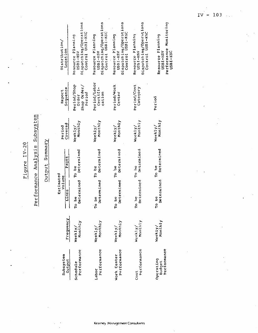
IV - 103
oCN
1
t 1
QJ
-J
O"1•H
fa
E
-p
^*tCO**13
CO
CO•HCO
,_,(0£
QJUC03E
OM-l
PM
x^CO
jj3
-^ .LiJJm
Q '
jju
a41E
•ooLI4>D.
^j03EE
CO
1)
Ou4J T33 41 41
0 £§E -I
— OAJ ^
in
c0
u10uS
1>:413tr4)JO
1341
4>>Ou
in41CPa.
inc
^
toc0
jjc^ ^C Li• O)c aC 0«H cnCL. > C
CO -H4i =: j=0 1 0
3 CD *^O W Q-W O I/I<y — •*K Q
a \O Li
CO T3
•O 41 G0 -0
Li O O41 JCa co
>,i— i
V^ r*1
*>^ JJ-H C^ O4) E41
3T
•D41C
e41
4) JJJO 4)
Q
H
T3
C— e41
41 JJ
O
UC/j*•<
1*-lC2003
^^OLl
C0o
•ooHLl41a
o;cO
•^•J
JJ Uen <s coC Ll iC
•-< 4> 1c a--'c o a10 \ W
a > cCO " i~i
4> S £ OO 1 O Li
3 CO (0 Co w a, oin o co u0) —ios o
U0
JO 1fO •••*i-3 y-i C
•O JJ -O Li JJ
— i 4) <0Li CJ O4>a.
>,.—i
v^ f"
^1 JJ-1 CJ^ O4) E41
•o41C
•gQ41
4) JJ
OoE-1
T34>C•*4
E4)
41 JJ
O
incO
*-H
JJ UC7^ O '1OC U X
— ' 4) 1C Qi »- <C O D10 \CO
f— I CT> Ocu > c
CO — " — iv = £ o. 0 1 0 Li
3 D (0 Co co a oin o in cj41 •»*
<£ Q
J^ij
OS L.V. 4)*Q Jj
o c-*4 c^U U41a.
>,i-H
x^ f>| JJ-H C.* O4> y4)
•D41C
"gC4>
41 JJ_ft 4*
QH
•D41C
14) .
0 JJ
Oe-
r^c-*^ccID,_ia00
3O
6c
jjKCO1
6••*L<Oa
\>.^H
JiTOas
V
0t-
j;cH
01co
•*4
JJ U.T 1CLi XS) 1
oa*^ ^oCT1 ^
> CJl -~* ~4
= ^ O1 0 Li
£ C CCTy C. 0
3 in u-«4
^
>1
LiOCTOjJ10)
><»^orjjco2
•—oce.Llc>JJ
c
.»;
O
E
O
42
c^c
•~4
c.c.10
w—i
c. >CO
41 =:U 1
o coW 34>o:
-co
-*•<
u010-
>l1— 1
^x «C>1 JJr* CX O41 £ClS
T34>C
ELiO
41 JJ
"" C0•
•c4)C
U41
O JJ
OE-
^tc—*LiOJJ
— *C0r010 CJC COt!3 Sr£E 1
O 03vu COLi 301a.
oca'3tr4>LiCu
>, JJ-H C>: On s:os
•?. °
£01JJ JJCO 3x ain JJJ3 33 O
CO
41OC10
4! Li-H O3 <JJ•D Li41 41z. ao
CO
41OC10E
Li LlO 41jo a10
4)o
Li C41 mJJ EC Li41 O
CJ ujLi
X. 0'
O
ou
EUOu-'U
JJ Ciin z.O
Kearney. Management Consultants

IV - 104
Table IV-13
Performance Analysis Subsystem
Key Output Data Elements
Subsystem Input
Schedule Performance
Key Data Element
DateShop OrderOperation NumberOperation Scheduled StartOperation Actual StartOperation Scheduled Due DateOperation Actual Due Date
Labor Performance DateShop Order NumberOperation NumberLabor CertificationLabor CertificationLabor Certification
CodeStandard TimeActual Time
Work Center Performance DateShop Order NumberOperation NumberWork Center CodeWork Center Standard Duration TimeWork Center Actual Duration Time
Cost Performance DateShop Order NumberOperation NumberResource CodeResource Standard CostResource Actual Cost
Operating BudgetPerformance
PeriodBudgetBudgetBudgetBudgetBudget
ElementElementElementElementElement
DescriptionBudgeted CostActual CostVariance
Kearney: Marwjjement Consultants
. IV - 105
SRB/APC INFORMATION FLOW
The SRB production control system information flow is shown
in Figure IV-21. It is described in the paragraphs below.
(a) LaunchSchedule
The launch schedule is the primary criteria for production
planning and scheduling. Refurbishment scheduling uses the
planned recovery schedules based on the launch schedule. Resource
planning uses the information from the launch rate, launch dates,
and the refurbishment schedule to plan resource requirements.
An objective of the SRB/APC system is to provide management
with needed information with sufficient lead time to make decisions
which ensure mission compliance.
(b) DesignEngineering
The design engineering function (sustaining engineering)
is responsible for the creation of and/or changes to:
1. Drawings.
2. Engineering bills of material.
3. Part master.
The impetus for design engineering changes and, therefore,
information flows, will come from:
1. Analyses of operations performance and exceptions.
2. Industrial engineering requests.
3. Flightworthiness improvement programs.
Kearney: Management Consultants
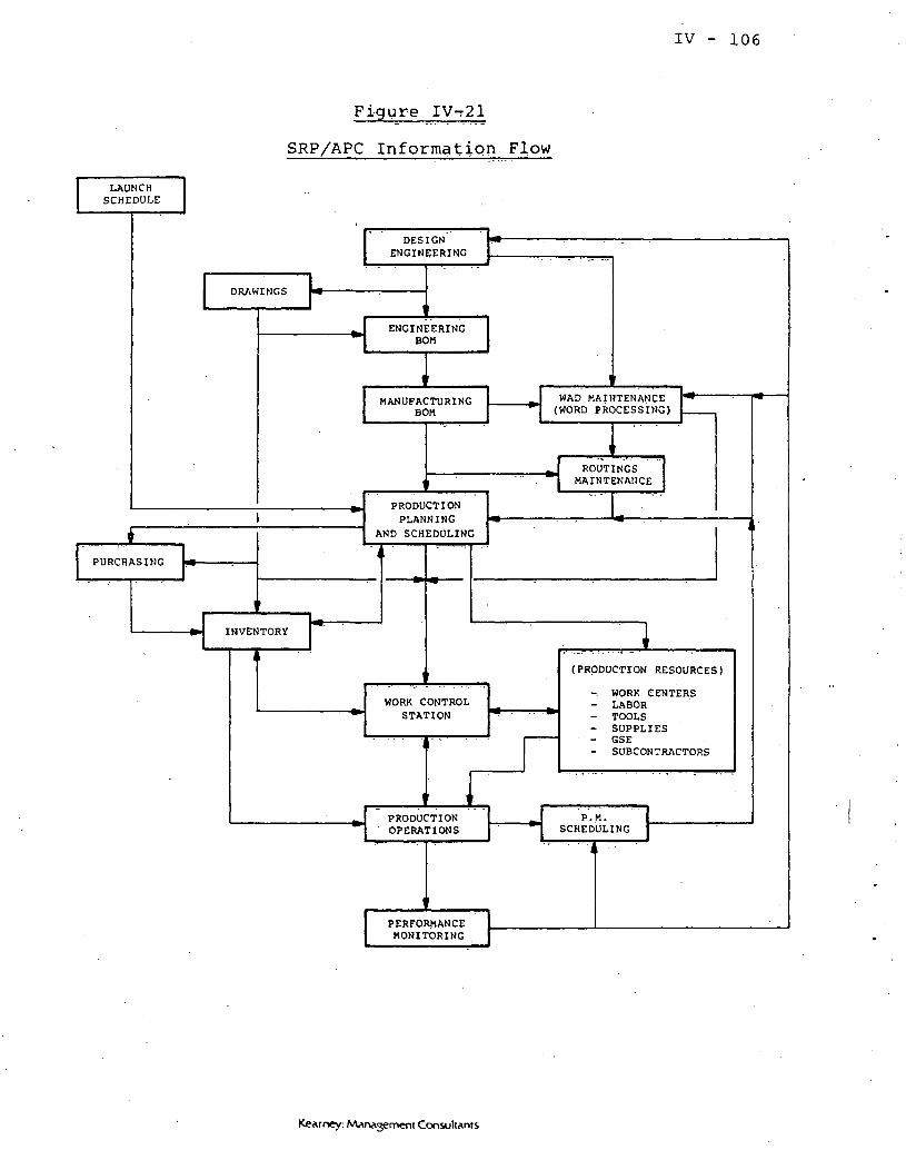
IV - 106
Figure IVr^l
SRP/APC Information Flow
LAUNCHSCHEDULE
DRAWINGS
PURCHASING
INVENTORY
DESIGNENGINEERING
ENGINEERINGBOM
MANUFACTURINGBOM
WAD MAINTENANCE(WORD PROCESSING)
PRODUCTIONPLANNING
AND SCHEDULING
ROUTINGSMAINTENANCE
WORK CONTROLSTATION
PRODUCTIONOPERATIONS
PERFORMANCEMONITORING
(PRODUCTION RESOURCES)
- WORK CENTERS- LABOR- TOOLS- SUPPLIES- GSE- SUBCONTRACTORS
P . M .SCHEDULING
Kearney: M^rvvjement Consultants

IV - 107
4. SRB and component useful life improvement programs.
* 5. Weight reduction programs.
6. Cost reduction programs.
7. Purchasing and vendor requests.
Design engineering information and the manufacturing BOM
will be used to trigger creation of, or changes to, WADs.
(c) Drawings
The drawings are the graphic representations (cartoons) of
the physical part or assembly. Drawings will be developed for
each item to be inventoried, and will be communicated from design
engineering to the engineering bill of materials.
Drawings are used for the following purposes.
1. Communications with vendors regarding part dimensions
and specifications.
2. Definition of part effectivity changes.
3. Graphic representation of engineering BOM com-
ponent installation location.
4. Production operations support information. The
drawings would be included in the job packet.
(d) Engineering BOM
The engineering BOM is a structured parts list (generation
breakdown). This list will identify each level of assembly and
the components of that level. For example, the SRB flight
Kearney: Management Consultants
IV - 108
set would be one level, an SRB another level, and the aft skirt
another level.
Engineering changes to drawings or part specifications would
require changes to the engineering BOM, thus requiring an informa-
tion flow.
(e) ManufacturingBOM
The manufacturing BOM is a revised structured parts list
based on the engineering BOM. This restructuring is required
to coordinate the materials flow to the production operations
flow.
This restructuring will include creation of new levels to
the BOM, or exclusion of some engineering BOM levels from the
manufacturing BOM.
The manufacturing BOM is the primary data source for the
time-phased material requirements explosion .of the production
master schedule, and therefore mus't be communicated' to produc-
tion planning and scheduling.
WAD and routing maintenance will use these manufacturing
BOMs as reference materials. Each level of the BOM will re-
quire a routing. Each operation of a routing will require a
WAD or a section of a WAD.
Parts lists previously included in the WAD could also now be
maintained in the manufacturing BOM. A time-phased release of
. Kearney Management Consultants

IV - 109
parts in multiple pick lists will be coordinated by a release
off-set lead time.
(f) WAD Maintenance
Work authorization document (WAD) maintenance is the main-
taining of current production process instructions. These docu-
ments are detailed narrative descriptions of every work step
required to perform a task.
Design engineering changes or production process changes
will require WAD rewrites or modifications. The volume of
narrative is not needed for production control purposes, but
hard copy WADs are needed on the shop floor to provide instruc-
tions to labor and to record quality inspection "buy-offs". As
a result of these needs for these voluminous documents and as a
consequence of frequent design or process engineering changes,
it appears to be most practical to maintain WADs on some type
of word processing equipment.
WADs relating to the assembly of one level in the manufac-
turing BOM are grouped into a routing network. Each WAD, or WAD
section, is summarized in a routing operation.
Hard copies of the WADs about to be released to the shop
floor are maintained in the work control station.
(g) RoutingMaintenance
Routing maintenance is the organization of production
operations needed to complete an assembly and includes the
Kearney: Management Consultants

IV - 110
the identification of resources required to perform each operation
Production operations will be org-ariized into a network of parallel
and series work activities.
Resources required by an operation will include:
1. Work centers.
2. Labor by skill certifications.
3. Supplies.
4. Tools.
5. GSE.
6. Subcontractor support.
7. Alternate resources.
Routings may be adjusted because of WAD or manufacturing
BOM charges. In addition, a routing operations sequence may
be changed based on feedback from production operations or in-
dustrial engineering.
Routings are the primary data source for loading and sched-
uling production resources. The time required at a work center
and the labor skills needed are scheduling constraints. The
scheduling of a shop order routing is adjusted to ensure that
scheduled work does not exceed the available capacities of con-
strained resources.
Kearney: \Vina3ement Consultants
IV - 111
(h) ProductionPlanning andScheduling .
Production planning and scheduling is the core of the pro-
duction control system. This activity includes:
1. Master scheduling.
2. Materials requirements planning.
3. Capacity requirements planning.
4. Shop floor dispatching.
Master scheduling takes the launch schedule and translates
it into a production schedule of new and refurbished major
assemblies. This subsystem module then validates that the
production resources required to meet the production schedule
will be available.
Materials requirements planning explodes the master sched-
ule into time-phased detailed materials requirements.
Capacity requirements planning explodes the materials
requirements schedule of production shop orders into detailed
time-phased resource requirements, including work center, labor,
tools, supplies, GSE and subcontractors.
Shop floor dispatching assigns available resources to each
production shop order and schedules the release of each shop
order. Shop orders are released to the shop floor through a
production work control station.
Kearney. Marwgemeni Consultants
IV - 112
The production and scheduling activity also incorporates
the various feedback loops in the system, and is therefore driven
by production operations and preventive maintenance scheduling,
performance monitoring and resource availability.
t(i) Purchasing
Purchasing receives purchase requisition information from
materials requirements planning. These requisitions are satis-
fied by placement of vendor purchase orders. Drawing's and part
specifications would accompany purchase orders when they are
placed.
Purchase orders and due dates would be recorded as a plan-
ned inventory receipt of materials.
(j) Inventory
Inventory is the central coordination point for SRB/APC
operations information. Each launch date, dictated by the launch
schedule, is a requirement for an inventory control item; i.e., an
SRB flight set. The shop order to stack this flight set is a
"replenishment order" which satisfies a launch date, but requires
major assemblies. Major assembly shop orders satisfy major
assembly requirements and so on down to material requirements,
which are satisfied by purchase orders or on-hand inventory.
The materials flow is coordinated through the inventory
system, and scheduled by exploding the manufacturing BOM.
Kearney AAarwgerneni Consultants
IV - 113
Inventory receipts recording data are accomplished with
purchase and shop order receiving documents. The purchase order
receiving documents would be_^released to receiving in hard copy
form as a receipt arrives. These receiving documents, which
may include part identification tags, then are sent with the
materials to inspection. The receiving personnel would enter
receiving information into a CRT. This information would include
purchased items received per planned receipt, date received and
by whom, serial number information, and the location of the
items (e.g., inspection). This automated record of receipts
would be used by purchasing to verify vendor invoices.
Inspection would receive a hard copy of the receiving doc-
ument plus the part "data pack" from the vendor. Inspection would
verify part flightworthiness, or determine rework needed to
make the part flightworthy. A rework shop order would assign a
rework status to the part; e.g., hold for rework, rework immedi-
ately, return to vendor, etc. Later allocation of that part to
a requirement would schedule the rework shop order to be due
when the part is required. Inspection would also review the
vendor data pack and enter relevant information into the part
"as built" configuration information file.
The shop order receiving documents will be included in the
job packet. This would be an input document used to signal the
completion of a shop order, and the location to which it was
moved. This location could be an inventory segregation area or
Kearney: Management Consultants

IV - 114
another work center if the shop order routing provides that
instruction.
Inventory disbursements recording data are accomplished
wi.th picking lists. Picking lists 'of materials -required by a
shop order are controlled by the manufacturing 'BOM. 'When a .S'hop
order is to be released to the production floor 'the :time-phased
release of materials associated with the shop order creates a
series of pick lists. These pick lists are used to disburse
parts to production as required.
Dispatching and the work control station activities will pre-
verify that the inventory is on hand to satisfy each picking list.
Shortages, or potential shortages, Will 'be expedited 'two ,to four
weeks in advance. Picking lists on which a part is .shorted -can
be released by a manual authorization, and the shorted '-part
would then be expedited and a shorted parts picking list created.
Pick lists would accompany the parts to the shop floor,
where parts and part serial numbers received would be recfrecked
against the pick list and acceptance would be indicated on the
list. The signed-off pick list .wou-ld then be turned in to the
work control station to become part of the "as ibuilt" hard
copy backup.
Pick lists would be printed in advance of picking to pro-
vide a capability to manually control picking activities needed
for shop floor activities. This manual control capability is
Kearney: Management Consultants

IV - 115
necessary to provide backup in case the SRB/APC system "goes
down".
Production planning and scheduling activities, purchasing
activities and shop floor activities will shift planned receipts
and disbursement schedules. Therefore, the documentation needed
to support receiving and disbursement will not be created until
needed. However, the information would be available through on-
line terminals, when requested.
(k) Work ControlStations
Work control stations are the major shop floor data collec-
tion and information distribution and control points. The activ-
ities performed in these stations will support shop floor
supervisors by supplying information needed to coordinate "people,
parts, and paper" (or information in a paperless environment) and
will support the SRB/APC information update needs by recording
data from the shop floor.
These work control stations will be located on the produc-
tion shop floor, close to the work being performed. These work
control stations would function similarly to the current "TAIR"
stations.
The work control station activity priorities will differ
based on the type of work being performed. For example, work
control station activities include WAD issuance, as built
configuration data collection, resource assignments, etc.,
Kearney: MArwvjement Consultants
• •;. . "• " • . ... -•- • " .. • • '•' IV. - 1.16
while the major activities of the work control stations are:
1. Assembly of job packet information.
2. Prerelease verification of resource availability
and resource assignment to each shop order.
3. Monitoring and control of shop floor operations.
4. Gathering of data to support SRB/APC system needs
and to provide configuration backup in hard copy, .as well as input
to other systems such as ACMS, ADRS, etc. ,
The critical nature of work control activities makes it
necessary to have job packets and resources verified .early
enough to provide manual backup in case the SRB/APC system
"goes down".
(1) Production Resources
Production resources are the resources needed to perform
work. Production planning and scheduling will provide work
scheduling capacity loading or requirements for the.se resources.
Work scheduling will be performed for each work center.
Production shop order operations will be queued at each work
center based on the shop order priority.
Capacity loading will be performed for work centers, and
labor certification. The time period (weekly) requirements will
be compared against the resource capacity available. Requirements
will be specified for tools, supplies, GSE and subcontractors.
Kearney Management Consultants

IV - 117
Work control stations will reverify the .assignment or com-
mitment of resources to a shop order, then release requisitions
to acquire these resources.
(m) ProductionOperations
Production operations is where work is performed. This activ-
ity is also responsible for reporting progress and exceptions.
Production operations supervisors receive job packet informa-
tion from the work control station. Inventory, and production
resources would be scheduled to be delivered to the appropriate
work center as work begins. This scheduling would be coordinated
by the work control station, but work center selection of opera-
tions from the queue would be' directed by the production super-
visor.
The production supervisor's performance will be monitored
against the operations queue priorities. Special circumstances
may require that the supervisor select other than top priority
operations. The system will identify most of these exceptions.
For example, some exceptions might be:
1. Material kits not picked.
2. Resources schedule delivery conflicts which may
cause adjustments to work center operations priorities.
3. Certified labor not available.
4. Need to expedite work for work centers of subsequent
operations. (This should adjust the shop order priorities.)
Kearney: Marwvjement Consultants

IV - 118
Actual work performed will be tracked through data capture
of operations progress, resource usage, and production exceptions
This information is reported back to the work control stationi '
which updates the SRB/APC system*
PM scheduling will also use exception information, as weil
as GSE usage history, to plan maintenance.
(n ) PM Scheduling
PM scheduling plans maintenance based on GSE usage, main-
tenance logs and production exceptions *, These scheduled PM
shop orders must be supported by WADs and routings.
PM orders use the same work centers and labor skill cer-
tifications as production shop orders. Therefore, capacity
loading and work scheduling will be performed by the same pro-
duction planning and scheduling activity.
(o) Performance.Monitoring
Performance monitoring will report the following:
1. Shop order schedule compliance.
2. Shop order .labor skill certification productivity.
3. Shop order work center utilization.
4. Configuration deltas.
5. Shop order exceptions.
6. Period schedule compliance.
7. Period labor productivity.
8. Period work center utilization.
Kearney: Management Consultants

IV - 119
9. Subcontractor schedule compliance.
10. GSE schedule compliance.
11. Materials shorted.
12. Cost variance analysis.
13. GSE history report.
These performance reports will provide feedback to design
engineering and process engineering, so that potential improve-
ments can be analyzed. In addition, these reports may trigger
PM work to be scheduled.
SRB PRODUCTION OPERATIONSFLOW EFFECTS ON WORKCONTROL STATIONS
The work control station emphasis changes based on the types
of work being performed. The following sections will describe
SRB/APC activities performed within each type of work. The SRB
production operations flow is illustrated in Figure IV-22 on the
following page.
(a) RecoveryOperations
The work control stations for recovery operations have four
major functions:
1. To assemble recovery order job packet.
2. To record changes to the recovery due dates.
3. To record recovery loss of an SRB.
4. To record actual time and labor against an operation
Kearney MArwjement Consultants
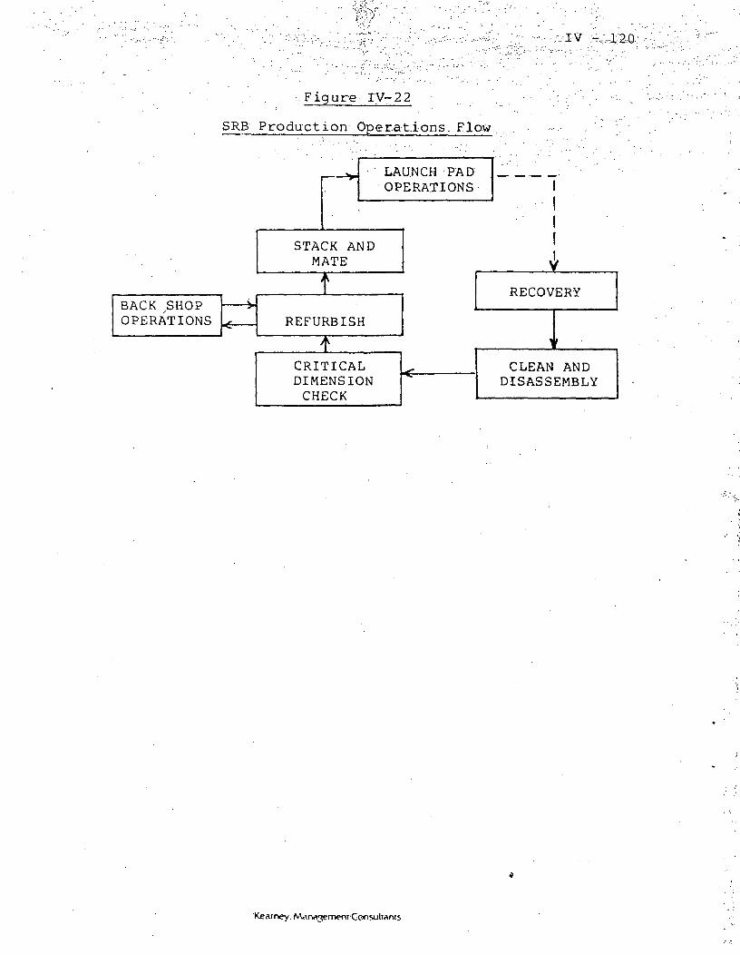
. Figure IV-22
SRB Production Operations. Flow.
LAUNCH PADOPERATIONS
STACK ANDMATE
BACKOPERATIONS REFURBISH
RECOVERY
CRITICALDIMENSIONCHECK
CLEAN ANDDISASSEMBLY
'Kearney. Management-Consultants

IV - 121
(b) Clean andDisassembleOperations
The work control stations for clean and disassemble operations
have the major objective of meeting a delivery schedule to provide
spent refurbishable major assemblies.
The work performed may be less critical than refurbishment,
and the labor skills may be more flexible; therefore, less control
of these resources may be needed.
The work control stations' major functions are:
1. To assemble clean and disassemble order job packets.
2. To schedule capacity of critical work centers.
3. To record changes to the spent assemblies due dates.
4. To record exceptional damage status for non-
refurbishable major assemblies.
5. To record actual time and labor against an operation.
(c) CriticalDimension Check
The work control stations for Critical Dimension Check opera-
tions have the major objective of recording Dimension Check results
which will determine materials needed and production resources
needed to perform refurbishment.
The work performed may not require materials but does require
special work centers, labor skill certifications and testing
equipment. Therefore, control is centered on work centers, labor
and tools.
Kearney: Man menr Consultants

IV - 122
The work control stations' major functions are:
1. To assemble testing order job packet information.
2. To schedule capacity of work centers (including hot
fire).
3. To schedule capacity of labor skill certifications.
4. To schedule tool requirements.
5. To record results of activities performed.
(a) Components to be replaced.
(b) Component test results.
(c) Probable component disposition.
6. To record changes to due dates.
7. To record actual time and labor against an operation
(d) Refurbishment andBuildup Operations
The work control stations for refurbishment and buildup
operations have two major objectives. These are to meet aisle
transfer schedules and to manage the utilization of scarce re-
sources.
The work to be performed uses critical work centers, labor
skill certifications, tools, GSE and subcontractors.
Work centers must be scheduled by operations priorities to
maximize work center utilization, and to achieve shop order due
date targets.
Kearney: Marvvjement Consultants

IV - 123
Labor skill certification must be scheduled by operations
priorities to maximize labor productivity and utilization (time
on standard measured work).
Tools, GSE and subcontractors must be supplied to scheduled
operations. The commitment schedules of shared GSE and subcon-
tractors may change schedule operation priorities for preceding
operations of the same shop order.
The work control stations' major functions for this type of
work are:
1. To assemble refurbishment and buildup order job
packets.
2. To schedule capacity of work centers.
3. To record shop order priority changes.
4. To provide current shop order priority and status
and to provide resource status information to shop floor super-
visors .
5. To record shop floor activity information.
(a) Work center start time.
(b) Work center stop time.
(c) Work center substitutions.
(d) Worker labor certification actualclock time on an operation.
(e) GSE and subcontractor time, loggedby operation.
Kearney: Management Consultants

IV - 124
6. To provide shop floor supervisors with the following
i nformation:
(a) Work center utilization.
(b) Labor productivity,
(c) Shop order schedule compliance.
(e) Back ShopOperations
The work control stations for back shop operations have the
major objective of creating or reworking components (LRUs) to
flightready status, as required by refurbishment or buildup
shop orders. This may also include effectivity upgrades, rework
requested by inspection, rework requested by life management, and
spent component rework.
The work performed requires materials, laborj and work prior-
ity management. The materials for rework will not always be known
until rework is in process. Labor loads will also be difficult
to plan for each order because the amount of rework required is
difficult to project. Work, priorities will primarily be set
based on part due date commitment to a refurbishment or buildup
shop order. Some back shop orders may be upgraded to inventory
stock, and may have a low priority.
The work control stations' major functions are:
1. To assemble back shop order job packets.
2. To record shop order priority changes.
Kearney: Management Consultants

IV - 125
3. To provide current shop order priority and status
changes to shop floor supervisors.
4. To input rework inventory requisitions to be communi-
cated to the inventory segregation area.
5. To alert shop floor supervisors and dispatchers to
potential work center or labor skill capacity problems.
(f ) Stack and MateOperations
The work control stations for stack and mate operations have
two major objectives. These are to meet work schedules which are
dictated by launch schedules and to manage.the utilization of
scarce resources.
The work performed uses critical work centers, labor skill
certifications, (including inspection certifications), tools, GSE
and subcontractors.
The scheduling difficulty of shop order operations is com-
pounded by resource availability, hazardous operations, and inte-
gration with other contractors.
The work control stations' major functions are:
1. To assemble stack and mate order job packets.
2. To schedule capacity of work centers.
3. To record shop order priority changes.
4. To coordinate resource assignments and shop order
operations priorities.
Kearney: Management Consultants

IV - 126
5. To provide current shop order priority and status to
shop floor supervisors.
6. To record shop floor activity information.
7. To provide shop floor supervisors with performance
information.
(g) Launch PadOperations
The work control stations for launch pad operations have the
major objective of coordinating work and resources with contractor
integration requirements.
The criticality of time available to perform an operation
mandates that resources be ready prior to start of that operation.
The work control stations' major functions are:
1. To assemble launch pad order job packets.
2. To ensure on-site arrival of all required resources
at the time needed.
3. To provide current shop order priority and status
changes to shop floor supervisors and dispatchers.
4. To coordinate schedule changes with contractor inte-
gration management.
Kearney. Management Consultants

V - COMPUTER SYSTEM DESCRIPTION
INTRODUCTION
In this section, Kearney's recommendations for the APC Computer
System are presented. Hardware requirements are defined in Section
VIII.
Section V is organized as follows:
Computer System Rationale - A discussion of key issues
considered in the computer system design.
High Level System Design - The proposed design is
presented in flowcharts and narrative.
File Definitions - The files identified in the high-
level design are described.
Evaluation of Existing NASA Systems - Eighteen
existing or proposed NASA systems are reviewed for their applica-
bility to the APC.
Conceptual Integration - A discussion of the conceived
integration or interface of ten NASA systems with the APC.
COMPUTER SYSTEMRATIONALE
1. Centralized versus Distributed. The two major loca-
tions with processing requirements are Huntsville (HSV) and Kennedy
Space Center (KSC). The ideal processing solution would be to
distribute the processing capacity (i.e., computer configurations)
and information capacity (i.e., data files) to the location with
primary responsibility for each activity associated with the
Kearney: Marwjement Consultants
V - 2
automated production control system.
For example, USBI/KSC could utilize its own computer to
process activities that primarily occur there (e.g., inventory
control, detailed capacity requirements planning, shop floor
reporting) and USBI/HSV could utilize its own computer to pro-
cess the activities that primarily occur there (e.g., master
scheduling, material requirements planning, purchasing, mainte-
nance to the manufacturing bills of material).
This approach would call for a distributed data base
capability to allow a singular automated production control
system to process data independent of file location. The
potential benefits of this approach would include reduced com-
munication costs, smaller computers in each location which could
provide reflective backup capabilities, and reduced risk of
total data base failure.
However, some of the difficulties posed by this approach
include data base concurrency control, security, administration,
and recovery.• The risks associated with these problems would
have to be weighed carefully against the potential benefits before
making the design decision.
The vendors offering manufacturing resource planning
software were each queried as to their capability to process in
a distributed data base environment. No vendor indicated that
they could. Thus to our knowledge, there is no existing software
on the marketplace which would support such a concept. Indeed,
distributive data base processing is a relatively .new art and much
Kearney. Management Consultants
V - 3
progress remains to be made before it is through its pioneering
stage.
Consequently, the approach recommended by Kearney util-
izes a centralized data base. This greatly facilitates control,
administration, security, and recovery of the data base.
The added communications cost is not significant since
the recommended location of the hardware is at KSC, where the
majority of processing occurs. The data base will be distributed
over multiple disk units to reduce the risks of total failure.
Backup hardware is provided to reduce the risks of processing fail-
ure.
2. Interactive versus Distributed Processing. The
recommended hardware architecture calls for interactive processing
from all distributed peripherals. It is recognized that there is
an opportunity to distribute some of the processing to peripherals
supported on-line by minicomputers or intelligent controllers.
This may be appropriate with the inventory control and shop floor
reporting subsystems. Primary transactions (e.g., issues, receipts,
labor reporting) could be collected interactively on minicomputers
and batched on a daily basis to the central computer(s). This
would relieve some of the communications load and central computer
processing requirements. The risk of processing interruptions
would be transferred from the potential failure of the communica-
tions network/central computer to the distributed minicomputers.
This could potentially reduce the risks of processing downtime.
The trade-offs to this approach are that it would call
Kearney. Management Consultants
V - 4
for customized programming at the minicomputer level, and increase
the problems of data control, backup, and security.
The recommended approach utilizes the design philosophy
of existing large-scale manufacturing resources planning software
packages, and offers the greatest control qver data transactions
and communications. The question of whether it may be more ad-
vantageous to distribute some portions of the system data entry
can be more concisely answered during the detail technical design
phase of the project.
3. Location of Central Computing Site. The recommended
location of the central computing site is Kennedy Space Center
for three primary reasons:
(a) Approximately 85% of the distrib^-uted peripherals are located inKennedy Space Center.
(b) There do not appear to be majorrequirements to interface withNASA/MSFC systems after the *SRBdesign responsibility is trans-ferred to USBI (estimated to be1983).
(c) There could be significant require?-ments to interface with KSC systems(e.g., KDMS, AUTOGQSS, Sims II) inthe years 1983 and beyond.
4. Backup/Contingency Provisions. The hardware
architecture, described in Section VIII, depicts backup disk storage
and access, tape storage and access, central processors and main
memory, printers, and communication controllers. This approach
is designed to minimize the risk of the failure of any critical
centralized hardware component that would cause system failure.
Kearney: Manasement Consultants
V .- 5
The distributed hardware (i.e., communication control-
lers, video display units, and printers) are user replaceable in
the field, should hardware failure occur there and not be restor-
able in an adequate time frame. It is recommended that a safety
stock (one or two each) of these equipment types be maintained in
the event of equipment failure.
The following section also defines levels of file backup
requirements according to the critical nature of the files. The
levels are defined as follows:
(a) H igh: Requires continuous audittrail transaction register, storedoff-site on daily basis. Requirescopy of complete file made onweekly basis and stored off-site. ,::
Objective: File recovery withinfour hours if needed.
(b) Medium; Requires continuous audittrail register, stored off-site onweekly basis. Requires copy ofcomplete file made on semimonthlybasis and stored off-site.
Objective: File recovery withineight hours if needed.
(c) Low; Requires continuous audittrail register, stored off-site onweekly basis. Requires copy ofcomplete file made on monthly basisand stored off-site.
Objective: File recovery within24 hours if needed.
Levels of backup requirements and specific plans to
accommodate these needs should be reviewed and refined during the
detail design phase.
5. Physical Security Requirements. The hardware must
Kearney NVuvvjement Consultants

V - 6
be physically protected from illegal access* Requirements for
the central computer site should include:
(a) Guards monitoring installationaccesses.
(b) All pe-rsonnel required to wearbadges.
(c) Sign-in and sign-out logs.
(d) Man-traps (i.e./ dual doors forsingular access).
(e) Electronic video observation equip-ment.
Security requirements for off-site storage need only
include items (b) through (d).
6. Access Security Requirements. Access security
requirements for the data base files which are discussed in the
following section are defined below:
(a) Critical; Requires terminal key,authorized terminal identifier,log-on password and data basepassword for read access.Requires two data base passwordsfor write access. Produceslogging trail of access whichmust be reviewed by USBI securityofficer.
(b) High; Requires terminal key, log-on password and data base passwordfor read/write capability.
(c) Medium; Requires terminal key,and log-on password for readcapability. Requires data basepassword for write capability.
7. Contingency Requirements. It is not recommended
that detailed backup manual methods be developed for SRB automated
production control contingency requirements. These contingencies
Kearney: Marvvjement Consultants

V - 7
should be accommodated by processing key activities (e..g. ,
printing material requisitions,., routings) at least eight hours
in advance of need. . .
The hardware manufacturer service levels should be
established for on-site call within two hours of system failure.
8. Existing NASA Processing Capacity. The processing
requirements of the APC system were reviewed against existing
capacity at KSC, NASA/MSFC, and Slidell. None of these locations
has or can make available adequate processing requirements to
accommodate the APC requirements.
HIGH LEVELSYSTEM DESIGN
In this section, a flowchart and accompanying narrative de-
picts system interfaces, inputs, updates and outputs for each of
the following mainstream subsystems:
Master Scheduling Subsystem.
Material Requirements Planning Subsystem.
Capacity Requirements Planning Subsystem.
- Shop Floor Management Subsystem.
- Operations Control Subsystem.
- Performance Analysis Subsystem.
jf-f,:\; . Kewrey.MAtwgenient Consultants

V - 8
(a ) MasterSchedulingSubsystem
The master scheduling subsystem is depicted in Figure V-l.
The.. la;unch schedule (1) is input into the system via CRT or
punched cards. This file is used to determine and anticipate
scheduled receipts of major assembly refurbished units by applying
the standard lead times to refurbish each unit (2), and creates a
file with this data in it (3). The automated production control
system provides the bill of materials (4) from which the major
assembly bill of materials file is extracted (5). the launch
schedule is exploded by using the major assembly bill of materials
to meet the launch schedule (6). These are known as the major
assembly gross requirements and are stored in a working file (7).
The current inventory status of major assemblies (9) is Extracted
from the automated production control system inventory status
file (8). A file of scheduled receipts of new build major assem-
blies (10) is extracted from the automated production control sys-
tem new build orders file (11). The availability of inventory to
meet the major assembly gross requirements over a time-phased
schedule is checked (12), by comparing the time-phased gross require-
ments (7) with the inventory status of major assemblies (9), sched-
uled receipts of new build major assemblies (10), and scheduled
receipts of refurbished major assemblies (3). The SRB major as-
sembly manufacturing order file (13) is created, reflecting the
orders to build new and/or refurbished major assemblies to meet
the launch schedule. This file is processed with the summary
Kearney. NUr«3ement Consultants

V - 9
l-{\
J>
<1)3Cn
• f-(Cu
e
W>-len1— 1o1 1
J— 'co
CJ
co"jjo3t30
Oi
T-j
0)4J(0604J
eQJ
CO>,tn•§en
enc
•H
3•oOJ.r;O
O4J(0(0£
*J X U
•isu o
S S 5 0
£1zu
(j O«
$0 Z
"2UH
u a. w- i qCJ u JXX. O.
C b. zu u
a a: 01
§< u&. uU < X
u u
0 •«01 0 >•
o ia
—O
Kearney: MArw\3ement Consultants

V - 10
resource requirements file (14) and the summary resource availa-
bility file (15) to determine the gross capacity plan and gross
operating budgets (16) which are produced as repor.ts (17). Based
on acceptability of the gross operating budget and gross capacity
plan, the solid rocket booster major assembly manufacturing orders
file (13) is passed to the material requirements planning subsys-
tem of the automated production control system, as the master
schedule (18). This master schedule is also available as a computer
printout (19).
(b) MaterialRequirementsPlanningSubsystem
The master schedule (I)/ produced in the master scheduling
subsystem, is input into the material requirements planning subsys-
tem (2), depicted in Figure V-2. The master schedule is processed
with the manufacturing bill of materials file (3), to produce a
detailed explosion (4), which identifies all of the gross material
requirements necessary to build the major assemblies and SRB (5).
The .manufacturing bill of material file is maintained with the
engineering data base and pending effectivities for new parts/
components (6), and the refurbishment forecasted bill of materials
estimates (7). The gross material requirements file (5) also be-
comes (by firm order) the "as designed" configuration for each launch
(8). This file will be used later to produce the "delta" report
between the "as designed" configuration and the "as built" configu-
ration. The inventory module (9) transactions provide for a current
Kearney: M/trvigement Consultants
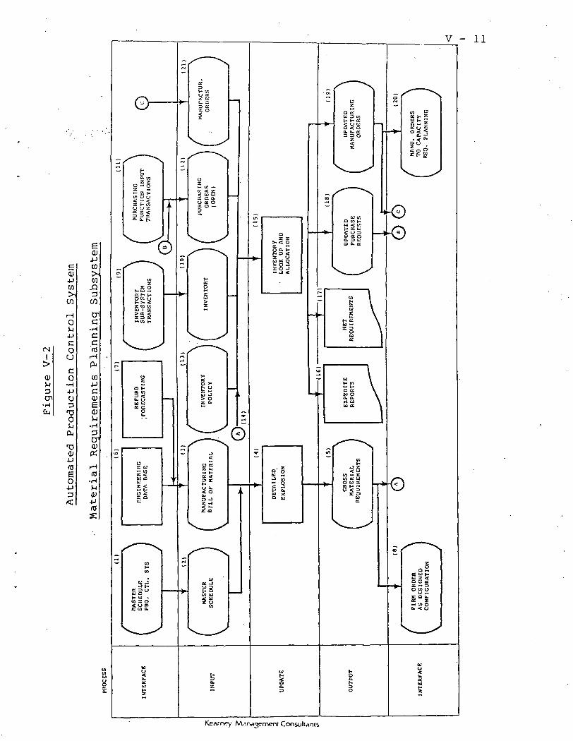
CNI
Q>
3Cn
E<D4JCO
CO
O
-ucouco
•H4J
uD
(X
T3CU4J03EO4J
- 11
Kearr>ey

V - .12
inventory status file for all parts associated with the solid
rocket booster (10). The purchasing function (11) transactions
create an open purchase order file (12) which reflects the sched-
uled receipts of parts. An inventory file (13) is maintained of
inventory policies which may dictate stock levels (e.g., safety
stock). The gross material requirement file is then processed (14)
with the inventory policy file, the inventory status file, the
open purchase order file, and existing manufacturing orders of
work-in-process (21) and an inventory look-up and allocation is
performed (15) to determine the current availability or scheduled
availability of parts to meet the gross material requirements. As
a result of this process, expedite reports may be generated (16)
to expedite the scheduled receipts of parts on current open pur-
chase orders. A report showing net requirements (i.e., part
requirements beyond current on-hand and scheduled receipts to meet
the gross material requirements) (17) is produced. Requests for
purchase orders (18) are produced to acquire the necessary parts
which are bought to meet the net requirements. Existing manufac-
turing orders are updated and new manufacturing orders are created
to build all of the various components and assemblies of the SRB
to meet the launch schedule (19). This file becomes the manufac-
turing orders file (20) which is passed to the capacity require-
ments planning subsystem.
KeArney

V - 13
(c) CapacityRequirementsPlanningSubsystem
The manufacturing orders produced in the material require-
ments planning subsystem (1) are input to the capacity requirements
planning subsystem (Figure V-3) as manufacturing orders (2). These
manufacturing orders are then translated into detailed shop orders
(3) by processing the manufacturing orders file with the routings
file (4). The routings file is maintained with the work authori-
zation document module (5). The output of this process is a file
of time-phased shop orders (6). This file is then merged with
preventive maintenance requirements file (7) which is created and
maintained by preventive maintenance transactions (8), the excep-
tion process documents file (9) which is maintained by the auto-
mated production control shop floor operations subsystem (10),
and the process constraints file (11). The detailed scheduling
process is then performed (12) to schedule not only the time-phased
shop orders but also preventive maintenance and exception processing
requirements within the limits of process constraints. This pro-
duces the detail scheduled shop orders file (13). These detailed
scheduled shop orders (14) are then processed with the work center
capacities file (15) and the resource and skill capacities (16)
and a load summarization (17) process is performed producing se-
veral outputs. The labor skill loads are reported (18), as are
the resource requirements (19). The work center capacity load and
rescheduling recommendations (20) report is produced and utilized
by the capacity planners to determine the extent of rescheduling
Kearney: Marvvjement Consultants

CO
>OJS-iDCn
0
a>(0Cu
w>ico
o4JcOCJ
o•H^JuD
T3O
cu'O<y4JfO
O-pD
V - 1.4
Kearney: A<^rw^3enr)ent Ccxisult

V - 15
E0)4JU)
I>
0)
CN
(N
Cn <Pcnto
cO
co4Ju3
O
cu
O
wJD3
cnc
•r-l
Cc03
•—IPu
W
C0)e0)S-i
3D1
(S
U(0
(0U
01cnu
Kearney M-irv»3ement Consultants

V - 16
required (21). Should there be a requirement for rescheduling,
the shop orders are rescheduled and reinput with the time-phased
shop orders (22) and the detailed scheduling module is reexecuted.
The major output of the capacity requirements planning subsystem
is the detailed production schedule file (23) which is then passed
to the shop floor management subsystem (24).
(d) Shop FloorManagementSubsystem
The detailed production schedule (1) from the capacity re-
quirements planning subsystem is input to the shop floor management
system (Figure V-4) as the detailed production schedule (2). In
order for prerelease verification to take place (3), the detailed
production schedule is compared with current inventory status of
parts (4) to determine if the required' materials are available,
and with the resource schedule file (6) to determine if the re-
quired resources are available. The inventory status file is main-
tained in the automated production control system (5). As a
result of the prerelease verification module, several outputs are
produced. Expedite messages (7) are produced to expedite the
availability of parts or materials required' for the detailed pro-
duction schedule. A dispatch package is printed to authorize
work to begin on operations in a detailed production schedule for
which parts or materials and resources are available (8). Resource
requisitions are printed (9) to draw upon resources; and materials
requisitions are printed (10) to draw the materials required1 for the
shop orders. Should some materials or resources not be available,
Kjearney: A/Urvvjement Consultants
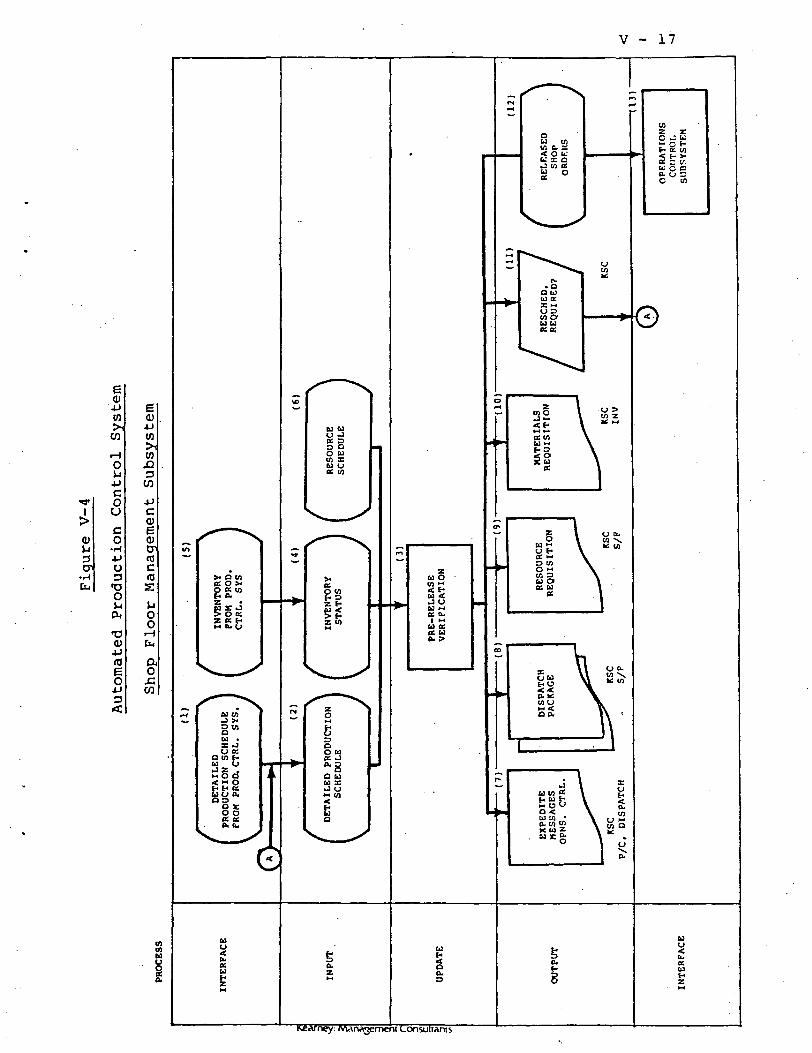
V - 17
0)VI3
••H[LI
4JCO>i
CO
Couco
•1-14Jo3TJOVICk
TJ(U-P
O4J3
r>earney: /vwvrwvjeme

V -r .18 . ' - . -
then there is a requirement to reschedule the shop order (11) and
the shop order will be reinput in its rescheduled mode at the
beginning of the shop floor management subsystem. The released
shop 'orders (12) are then passed to the operations control sub-
system (13 ). .
(e } . OperationsControlSubsystem
The released shop orders (1) are passed to the operations con-
trol system (Figure V-5) from the shop floor management subsystem
(2). All activity against the released shop order is posted to
the shop order file. This includes materials released for the
shop order (3), exception material issued to the shop order ( ),
resource usage against a shop.order (5), labor expended for a
shop order (*>), exception processes and rework for the shop order
(7), and schedule changes to the shop order (^), These activities
are posted against the shop order file (9). A file of materials
installed against the shop order (10) is maintained and utilized
by the automated configuration management system to produce the
"delta" reports showing variances between the "as designed" eonfigu-
ration and the "as built"* configuration (H). Exception reports
are produced as necessary (12). Status reports of the shop orders
are produced '(13). Files are maintained of updated shop orders
(14), completed shop orders (i5), and all activity posted against
* This comparison between "as built" versus "as designed" willprobably not be in sufficient detail to satisfy the NASAbuy-off requirements. As a result ACMS, or a similar system,will probably be needed.
Kearney; Management Consuliants

inI
QJiJ3CT>
•HCu
e<D
CO
oS-iJ->co
CJ
co
•l-(4JuD
TDOS-i
(0EO
Kearney: Management Consultants

V - 20
the shop orders (16). These files are passed to the performance
analysis subsystem (17).
(f) Performance . kAnalysisSubsystem
The operations control subsystem provides three files (1) to
the performance analysis subsystem (Figure V-6). These files are
the updated shop orders completed shop orders and activity data.
These three files are input to the performance analysis subsystem
(2) and are used to compare actual performance against the plan
(3). Various reports are produced, including the scheduled per-
formance report (4), the labor performance report (5), the work
center performance report (6), the cost performance report (7)
and the operations budget performance report.
FILE DEFINITIONS
Each of the files depicted in the high-level flowcharts is
described in more detail in this section.
Each file is described as follows:
1. Purpose. The reason for the file's existence.
2. Source. Which functional organization creates and/ort
maintains the file.
3. Mode of Input. The type of input medium used to
create and/or maintain the file.
4. Key Data Elements. The primary data fields associated
with the file and estimated field lengths. The total of the field
Kearney: M^rwvjemeht Consultants

V - 21
fc,
eOJ4Jin
en
Oujjcoo
co
oD
oQ*
T5O-P(0eojja<
eOJ^jin>,inXID
CO
w
(0c
0)uc(0eS-io
U-li-J0)a<
e.O
0 -enK aH uE o-= .au >oa. ••
OU
US •- Q COCJO H03 e to• •or Joo a.csec HCbk. U
nto1C
ECu
o
a
DE
TA
ILE
DP
RO
DU
CT
IOS
CH
ED
ULE
a.z
M
b.
11W O
5Cx
1
£K
Kearney Marvvjemeni ConstilMnts
. . V - 22 - ,..
lengths is the e.stimated record length of the file. It is recog-
nized that in actual operation the record may contain- additional
data fields for other internal or external system purposes. The
probable key(s) to each file are denoted.
5. Number of Records. An estimate for the number of
records each file will contain.
6. File Size. The record length times the estimated
number of records.
7. Processing Location. Where in the system the file
is created, processed, and/or maintained.
8. Peripheral Requirements. The noncentral hardware
requirements required to create/maintain and; print the file. Each
piece of hardware is designated with a code number which will be
referred to in Section VIII.
9. Access Requirement. The time frame during the day
when the file must be accessible for on-line use.
10. Criticality of Response Time. An estimate of the need
for quick response to use of the file.
11. Security Requirements. A classification of the meas-
ures that should be used to prevent unauthorized access to the
file. The classification scheme is described in a previous section.
12. Backup Requirements. A classification of the actions
that should be taken to ensure the capability to restore the file
should the need occur. The classification scheme is described in
a previous section.
Besides presenting an overview of the APC data requirements,
Kearney. Management Consultants

"--- 23
this section develops the volume estimates us'ed-:' 0--fi''d|,M't.-ify-. the
disk storage requirements in Section VIII. Av':siti'mma.. '":;p£'.;-'the files
completes this section." . / ' vi ' f' ?:—"••
(a) Launch ScheduleFile
Purpose
This file is input to the master scheduling module. It
represents the customer's orders for which material, labor, and
other resources will eventually be scheduled to build the re-
quired solid rocket boosters.
Source
NASA provides the launch schedule to USBI.
Mode of Input "
It is anticipated that the Master Scheduling Subsystem will
be manual during the early project stages. When the subsystem is'
automated at a later date, the mode of input would be direct
entry through a•CRT or punched cards.
Key Data Elements
Name
1. Launch Number ( K e y )
2. Launch Date
Total
Number of Records
Estimated Field -.Length
N3
N6
9 Bytes
One per flight; total number dependent upon number of flights
Kearney. Management Consultants

• • • ' . . . . . ..'_ "• - -... ; ' • ' V - 24
being scheduled. For purposes of estimating related files, it Is
assumed that 200 flights are being scheduled (.representing a
five-year time frame).
File Size
200 records x record length of 9 = 1800 bytes = .. 002
megabytes (MB).
Processing Location
Entry to be done at USBI (Resource Planning).
Peripheral Requirements
One CRT (designated Al); one printer (designated PI).
Access Requirement
As required.
Criticality of Response Time
Medium.
Security Requirements
Medium.
Backup Requirements
Low.
(b) Major AssemblyManufacturingBill ofMaterials
Purpose?
This file is input to the master scheduling module and is

V - 25
used with the launch schedule file to determine the due dates for
each of the major assemblies associated with each flight.
Source
This file is extracted from the automated production
control system manufacturing bill of materials.
Mode of Input
Interface from Automated Production Control System.
Key Data Elements
Name Estimated Field Length
1. Part Number (Key) A15
2. Part Description A26
3. Final Assembly LeadTime • R3
Total 44 Bytes
Number of Records
Estimated to be thirty major assemblies per SRB flight
set.
File Size
30 x 44 = 1,320 bytes = .001 MB.
Processing Location
In the central computer.
Peripheral Requirements
None.
Kearney MArwjjement Consultants

V - 26
Access Requirements
As required.
Security Requirements
Medium.
Backup Requirements
Low.
(c) Major AssemblyInventory File
Purpose
This file is used to determine if major assemblies currently
exist in stock.
Source
This file is extracted from the automated production control
system inventory status file.
Mode of Input
Interface from Automated Production Control System.
Key Data Elements
Name .. Estimated .Field Length
1. Part Number (key) A15
2. Quantity-on-Hand/Planned R2
3. Due Date (if planned) N6
Total 23 Bytes
Kearney: Management Consultants

V - 27
Number of Records
Thirty (one for each major assembly) per flight set x 200
flight sets = 6,000.
File Size
6,000 x 23 = 138,000 bytes = .138 MB.
Processing Location
Within central computer.
Peripheral Requirements
None.
Access Requirements
As required.
Security Requirements
Medium.
Backup Requirements
Low.
(d) Major AssemblyNew Build OrdersFile
Purpose
This file is used to provide the scheduled receipt dates
of new major assemblies.
Source
This file is extracted from the automated production
control system new build order file.
Kearney: Management Consultants

V - 28
Mode of Input
Interface from Automated Production Control System.
Key Data Elements
Name Estimated Field Length
1. Part Number (Key) A15
2. Scheduled Completion Date N6
3. Quantity To Be Completed R2
Total 23 BytesNumber of Records
Dependent upon number of new assemblies being built.
Probably would not exceed 100 at any given time.
File Size
100 x 23 = 2,300 bytes = .002 MB.
Processing Location
Within central computer.
Peripheral Requirements
None.
Access Requirements
As required.
Security Requirements
Medium.
Backup Requirements
Low.
Kearney: Marwjjement Consultants

V - 29
(e) Major AssemblyRefurbishmentSchedule File
Purpose
This file is used to provide the estimated scheduled receipt
dates of refurbished major assemblies.
Source
This file is created in the master scheduling module by
calculation. For each refurbishable assembly, "x" days
are added to the launch date for SRB recovery, and then the
average refurbishment lead time is added to determine the
estimated date for scheduled receipt of the refurbished
major assembly.
Mode of Input
None; this file is created.
Key Data Elements
Name Estimated Field Length
1. Part Number (Key) A15
2. Scheduled Receipt Date N6
Total 21 Bytes
Number of Records
Estimated to be 10 per launch. For the assumption of a
200-launch horizon, there would be 2,000 records.
File Size
2,000 x 21 = 42,000 bytes = .042 MB.
Kearney: Marwvjement Consultants

V - 30
Processing Location
Within central computer.
Peripheral Requirements
None.
Access Requirements
As required.
Security Requirements
Medium.
Backup Requirements
Low.
(f) Major AssemblyGrossRequirements
Purpose
This file represents the due dates for completion of major
assemblies to accomplish the launch schedule.
Source
This file is created in the master scheduling module by
using the launch dates from the launch schedule file and the
major assembly requirements and lead times to determine the
due dates of major assemblies and activities.
Mode of Input
None, this file is created in the master scheduling module
Kearney; Management Consultants

V - 31
Key Data-Elements
Name Estimated Field Length
1. Major Assembly Number (key) A15
2. Description A26
3. Due Date N6
Total 47 Bytes
Number of Records
30 per launch. Assuming a planning horizon of 200 launches,
there would be 6,000 records.
File Size
6,000 x 47 = 282,000 bytes = .282 MB.
Processing Location
Within central computer.
Peripheral Requirements
None.
Access Requirements
As required.
Security Requirements
Medium.
Backup Requirements
Low.
Kearney: Management Consultants
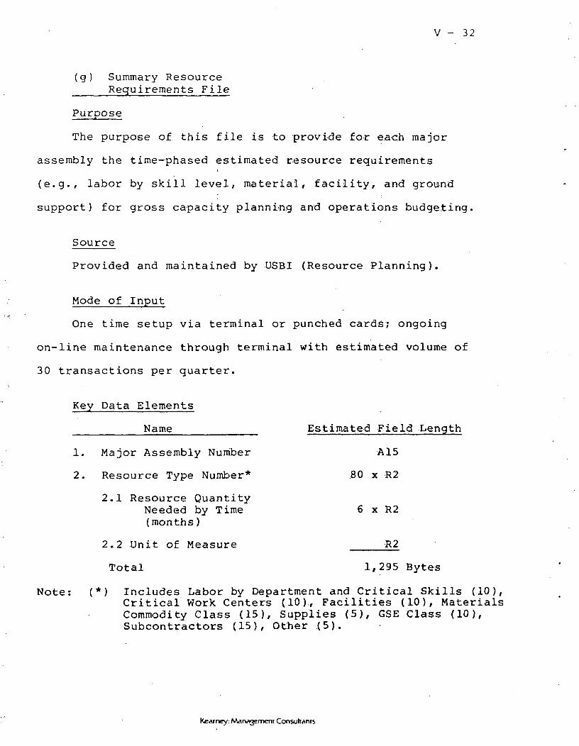
V - 32
(g) Summary ResourceRequirements File
Purpose
The purpose of this file is to provide for each major
assembly the time-phased estimated resource requirementsi
(e.g., labor by skill level, material, facility, and ground
support) for gross capacity planning and operations budgeting.
Source
Provided and maintained by USBI (Resource Planning).
Mode of Input
One time setup via terminal or punched cards; ongoing
on-line maintenance through terminal with estimated volume of
30 transactions per quarter.
Key Data Elements
Name Estimated Field Length
1. Major Assembly Number A15
2. Resource Type Number* 80 x R2
2.1 Resource QuantityNeeded by Time 6 x R2(months)
2.2 Unit of Measure R2
Total 1,295 Bytes
Note: (*) Includes Labor by Department and Critical Skills (10),Critical Work Centers (10)., Facilities (10), MaterialsCommodity Class (15), Supplies (5), GSE Class (10),Subcontractors (15), Other (5).
Kearney: Management Consultants

V - 33
Number of Records
30.
File Size
1,295 x 30 = 38,850 bytes = .039 MB.
Processing Location
Input via CRT from USBI headquarters, Huntsville.
Peripheral Requirements
One CRT (designated Al); one printer (designated PI).
Access Requirements
0800-1700 Daily.
Criticality of Response Time
Medium.
Security Requirements
Critical.
Backup Requirements
High.
(h) Summary ResourceAvailability File
The purpose of this file is to identify planned availability
of resource by time period (monthly for five years).
Source
Provided and maintained by USBI (Resource Planning).
Kearney: Management Consultants
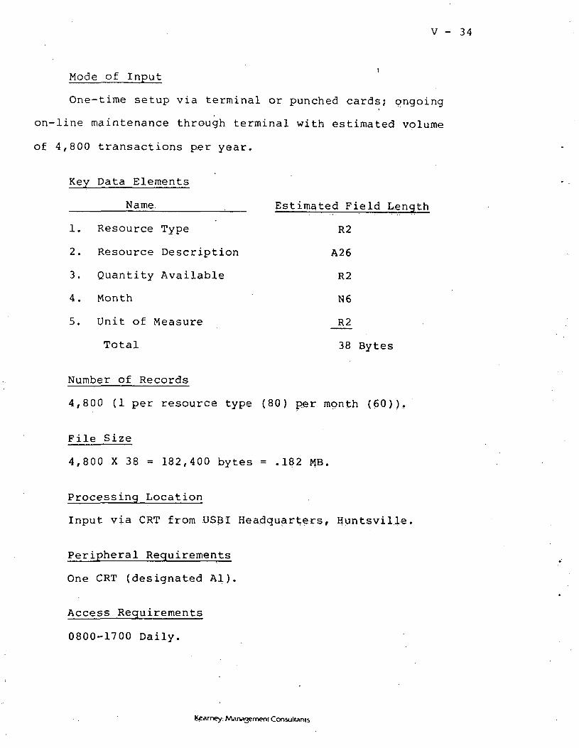
V - 34
Mode of Input
One-time setup via terminal or punched cards; ongoing
on-line maintenance through terminal with estimated volume
of 4,800 transactions per year.
Key Data Elements
Name. . Estimated Field Length
1. Resource Type R2
2. Resource Description A26
3. Quantity Available R2
4. Month N6
5. Unit of Measure R2
Total 38 Bytes
Number of Records
4,800 (1 per resource type (80) per month (60)).
File Size
4,800 X 38 = 182,400 bytes = .182 MB.
Processing Location
Input via CRT from USBI Headquarters, Huntsville.
Peripheral Requirements
One CRT (designated Al).
Access Requirements
0800-1700 Daily.
: MArv^ement Consultants
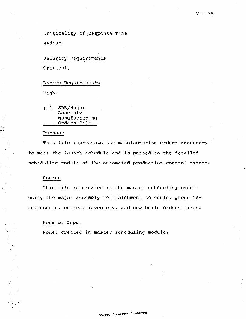
V - 35
Criticality of Response Time
Medium.
Security Requirements
Critical.
Backup Requirements
High.
(i) SRB/MajorAssemblyManufacturingOrders File
Purpose
This file represents the manufacturing orders necessary
to meet the launch schedule and is passed to the detailed
scheduling module of the automated production control system.
Source
This file is created in the master scheduling module
using the major assembly refurbishment schedule, gross re-
quirements, current inventory, and new build orders files.
Mode of Input
None; created in master scheduling module.
K£Arncy: Management Consultants

V - 36
Key Data Elements
Name Estimated Field Length
1. Major Assembly/Number (key) A15
2. Due Date N6
3. STS Number (key) R2
4. Order Type (new or refurb) Al
5. Major Assembly Serial Number AID
Total 34 Bytes
Number of Records
Assuming a launch horizon of 200 flights, and 30 major
assemblies per flight, there would be up to 6,000 records
(some major assemblies may be in stock or be work-in-process).
File Size
6,000 x 34 = 204,000 bytes = .204 MB.
Processing Location
Within central computer.
Peripheral Requirements
None.
Access Requirements
As required.
Security Requirements
Medium.
Kearney: MArw^jement Consultants

V - 37
Backup Requirements
To be backed up immediately after each creation,
(j) ManufacturingBill Of MaterialFile
Purpose
The Bill of Material (BOM) File provides the parts and
their relationship to higher/lower assemblies data necessary
to explode the major assembly requirements into the components
and parts that make up those assemblies. It also provides
the lead time necessary to acquire or assemble a part/component.
Source
The current engineering BOM is maintained in the engineering
data .base. The manufacturing BOM is extracted from that data
base.
Mode of Input
None; the file is maintained through an integration with
the engineering data base.
Kearney: Management Consultants

V - 38
Key Data Elements
Name Estimated Field Length
1. Parent Part Number A15
2. Component Part Number A15
3. Quantity Used R4
4. Find Number 12
5. Effectivity (by STS NumbersFrom/To) 2 x 13
6. Unit of Measure 2 X 12
7. Engineering Change Number R2
8. Engineering Change Date N6
9. Drawing Number A1Q
Total 64 Bytes
Number of Records
There are an estimated 250,000 items in the bill of
material, assuming effectivity changes by line item or component
record.
File Size
250,000 x 64 = 16,000,000 bytes = 16.0 MB.
Processing Location
USBI/HSV Design Engineering; USBI/KSC Process Engineering;
USBI/KSC Quality Assurance.
Peripheral Requirements
3 CRTs (designated A2, A3, and Kl); 2 Printers .(designated
PI and P2).
Kearney. Management Consultants

V - 39
Access Requirements
24 hours per day.
Criticality o£ Response Time
High.
Security Requirements
High.
Backup Requirements
High.
(k) Inventory File
Purpose
This file is a multipurpose file. In addition to tracking
•inventory levels through issues, receipts, cycle counts, and
adjustments, the inventory data base provides the key record for
storing other records (e.g., serialized part information, configu-
ration data).
Source
The file is primarily maintained by the inventory control
function of the production control system.
Mode of Input
Assuming 50,000 .controlled parts per SRB, there are likely
to be 1,000,000 transactions in the system on an annual basis
(i.e., 12 flows + additional stock). Therefore, the mode of
Kearney: Marvijjement Consultants
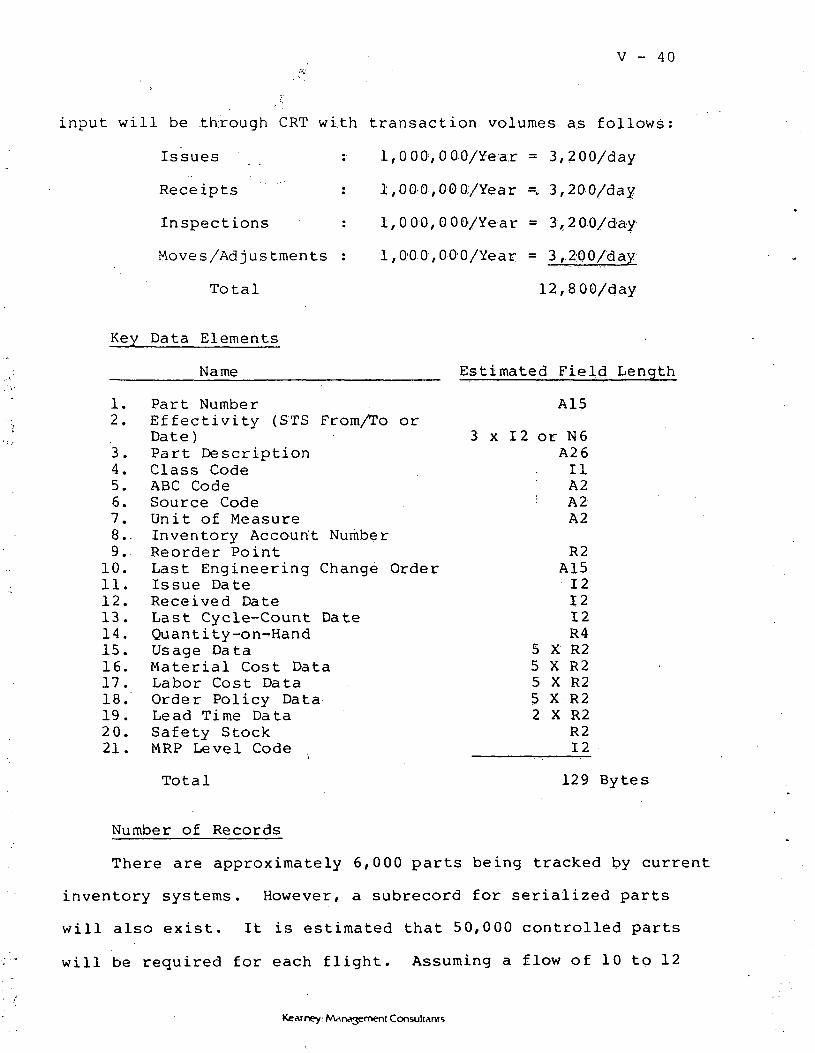
V - 40••"V
input will be .through CRT with transaction volumes as follows:
Issues : 1,000,000/Year = 3,200/day
Receipts : 1,000,000/Year =,. 3,200/day
Inspections : 1,000,000/Year = 3,200/day
Moves/Adjustments : 1,0:00,000/Year = 3,200/day
Total 12,800/day
Key Data Elements
Name Estimated Field Length
1.2.
3.4.5.6.7.8..9.
10.11.12.13.14.15.16.17.18.19.20.21.
Part NumberEf fec t iv i ty (STS From/To orDate)Part DescriptionClass CodeABC CodeSource CodeUni t of MeasureInventory Accoun't NumberReorder PointLast Engineering Change OrderIssue DateReceived DateLast Cycle-Count DateQuant ity-on-HandUsage DataMaterial Cost DataLabor Cost DataOrder Policy DataLead Time DataSafety StockMRP Level Code
A15
3 x 12 or N 6A2611A2
'•• A2A2
R2A15
121212R4
5 X R25 X R25 X R25 X R22 X R2
R212
Total 129 Bytes
Number of Records
There are approximately 6,000 parts being tracked by current
inventory systems. However, a subrecord for serialized parts
will also exist. It is estimated that 50,000 controlled parts
will be required for each flight. Assuming a flow of 10 to 12
Kearney: Management Consultants

V - 41 .
flights, there will be 500,000 to 600,000 records.
File Size
600,000 x 129 = 77,400,000 bytes = 77.4 MB.
Processing Location
Inventory Segregation Areas (KSC).USBI Headquarters, Huntsville.
Peripheral Requirements
Based on 12,800 transactions per day, and a 20-hour day,
the processing rate would be 640 transactions per hour. Assuming
a throughput of 60 transactions per hour per terminal, 11 CRTs
would be required. An additional 6 CRTs would be provided
for inquiry and maintenance for a total of 17 CRTs, 14 in
KSC (designated K2 through K15), and 2 in Huntsville (designated
A4, A5). Two printers (P3, P4) would be needed at KSC; printer
PI can be used for Huntsville.
Access Requirements
24 hours per day.
Criticality of Response Time
High.
Security Requirements
High.
Backup Requirements
High.
Kearney: Marwyment Consultants

V - 42
(1) Purchase OrderRequest File
Purpose
In addition to its use in a purchasing system (off-line),
the purchasing order request file would' be used by the MRP
module to provide data' related to scheduled receipts of
materials.
Source
Interface from purchasing subsystem (off-line).
Mode of Input
None; extracted from purchasing subsystem (off-line).
Key Data Elements
Name E's t i ma ted F i e Id; Length
1. Part Number (key) A15
2. Purchase Order Number A10'
3. Order Quantity R2
4. Purchase Order Unit Cost R2
5. Due Date 12
6. Vendor-Promised Delivery Date 12'
7. User-Specified Delivery Date 12
8. Quantity Returned to Vendor R2
9. Vendor Code A10
10.. Account Number . A. 1-0.
Total 57 Bytes
Kearney: Management Consultants

V - 43
Number of Records
Estimated to be about 1,000 open P.O.'s.
File Size
1,000 x 57 = 57,000 bytes = .057 MB.
Processing Location
USBI/HSV (Purchasing).
Hardware Requirements
Two CRTs for purchasing designated A4 and A5. One
printer (designated PI).
Access Requirements
24 hours per day.
Criticality of Response Time
Medium.
Security Requirements
Medium.
Backup Requirements
High.
(m) Gross. Requirements File
Purpose
The gross requirements file contains all the assemblies/parts
required to meet the master schedule.
Kearney: Management Consultants

V - 44
Source
Created in the MRP module.
Mode of Input
None; it is a created file.
Key Data Elements
Name Estimated Field Length
1. Part Number/Effectivity (key) A15
2. Required Quantity R2
3. Required Date 12
4. STS Number ' R2
5. Next Higher Assembly A15
6. Serial Number AlO
Total • 46 Bytes
Number of Records
Assuming a launch horizon of 120 flights and 50,000
assembly parts per flight, there would be 6,000,000 records.
File Size
6,000,000 X 46 = 276,000,000 bytes =276 MB.
Processing Location
Within central computer.
Peripherals Required
None.
Kearney: Management Consultants

V - 45
Access Requirements
As required.
Security Requirements
High.
Backup Requirements
High; this file should be backed up immediately
after creation.
(n) ManufacturingOrder File
Purpose
The purpose of the manufacturing order file is to provide
the information regarding the due dates of assemblies required
during the manufacturing process.
Source
This file is created through the netting logic of the MRP
module.
Mode of Input
None, it is created by the Material Requirements Planning
Subsystem.
Kearney: Management Consultants

V - 416
Key Data Elements
Name Estimated, Field, Length
1. Part Number/Ef.factivity (key)- A15
2.. Planned Quantity ' R2
3, Start Date " 12
4.. Due Date 12
5. Next Higher Assembly . A15
6. Launch. Number 12:
Total 38 Bytes.
N.'umber of Records
Assuming a launch horizon of 120; flights, and up to 50,000
manufacturing orders requ-ired: per flight,, there could- be up to
6,000,000 records.
File Size
6,000,000 x 38. = 228,,0;00,00.0; bytes =? '228, MB.;
Processing Location
Within central computer.
Peripheral Requirements
Non,e.
Access .Requirements
24 hours per day.
Criticality of Response Time
High.
Kearney: Marw»3emeni Consultants
V - 47
Security Requirements
High.
Backup Requirements
Critical.
(q) Routing File
Purpose
The routing file provides the detailed operations for each
shop order, showing work centers, operations, GSE requirements,
tooling requirements, and labor requirements by skill.
There would also be routings to: (1) upgrade the effectivity
of a part; (2) -rework a part to flightworthy status; and
(3) other purposes as required.
Source
This file is maintained in conjunction with the Work
Authorization Document system by USBI/KSC (Process Engineering).
Mode of Input
Batch one time setup. On-line maintenance (daily).
Kearney: Marvvjemeni Consultants

V - 48
Key Data Elements
Name Estimated Field Length
1. Part Number (key) A15
2. Sequence Number 12
3. Operation Code (key) A10
4. Operation Description A30
5. Tool Numbers 5 x A10
6. Work Center A10
1. Standard Setup Hours R2
8. Standard Run Hours R2
9. Standard Transit/Queue Hours R2
10. GSE Requirements 5 x A20
11. Labor Skill/Certification. Requirement 5 x A30
Total 373 Bytes
Number of Records
20 Fits x .250 Routings = 5,000 Records + 1,0-00 Baseline
Routings = 6,000 records x 5 operations per routing =
3.0,000 records.
File Size
3 0 , 0 0 0 x 373 = 11,190,000 bytes = .11.19 MB.
Processing Location
Used w i th in central computer; mainta ined by USBI/KSC
Process Engineering.
.Kearney: Management Consultants

. . . . V - 49
Peripheral Requirements
I CRT (K60.)
Access Requirements
24 hours daily.
Criticality of Response Time
Medium.
Security Requirements
High.
Backup Requirements
High.
(p) Exception ProcessDocuments File
Purpose
To provide work orders for exception processes (TPS, DR, PR)
for incorporation in the scheduling module.
Source
USBI/K3C Shop Floor and USBI/KSC Process Engineering.
Mode of Input
CRT.
Kearney: Management Consultants

y - so
Key Data Elements
Name Estimated Field Length
1. Part Number (key) A15
2. Sequence Number 12
3. Operation Code (key) Al.O
4. Operation Description A3Q
5. Tool Numbers 5 x A10
6. Work Center A 1,0
7. Standard Setup Hours R2
8. Standard Run Hours R2
9. Standard Transit/Queue Hours R2
10. GSE Requirements 5 x A20
11. Labor Skill/Cert ificationRequirement 5 x A3Q
Total 373 Bytes
Number of Records
Estimated to be 4,000 records; ongoing maintenance estimated
jto be 25 records per day.
File Size
373 x 4,000 = 1,492,000 bytes = 1.49 MB.
Processing Location
USBI/KSC Shop Floor and Process Engineering.
Peripheral Requirements
2 CRTs (Kl, K16), in addition to shop floor terminals.
Kearney: M-in^gement Cqn.suli.$nts

V - '51
Access Requirements
24 hours per day.
Criticality of Response Time
High.
Security Requirements
High.
Backup Requirements
High.
(q) ProcessConstraintsFile
Purpose
To identify specific routings that prohibit the simultaneous
performance of other routings due to the nature of the specific
routing.
Source
USBI/KSC (Process Engineering).
Mode of Input
CRT.
Kearney: Management Consultants
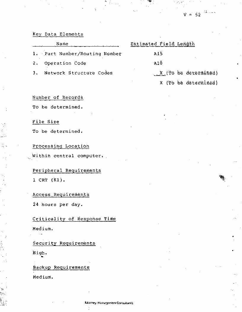
V - 52
key Data Elements
Name .
1; '.Part Number/Routing Number
2. Operation Code
3. Network Structure Codes
Estimated.. Fi.eia, Le.nf.feh
A15
AlS
. . X/(I'd fee aet'ermin§a')
X (To be a'efcermlMal
Number, of Records.
To be determined;
File Size
To be determined;
Process ing Loca.tib.n
Within central computers
Peripheral Requirements
1 CRT (Klj.
.Access,. R.equirernen.ts
24 hours per day.
Criticality of Response Time
Medium.
Security Requirements
High.^
Backup Requirements
Medium.
rney: Afl v<2emi•nt Cbnsultflnts

. ; V - 53
• t
(r) GSE PreventiveMaintenance WorkOrders
Purpose
To provide work orders for preventive maintenance for
scheduling purposes.
Source
Input by USBI/KSC (Preventive Maintenance).
Mode of Input
By CRT daily.
Key Data Elements
Name Estimated Field Length
,1. Part Number (key) A15
2. Sequence Number 12
3. Operation Code (Key) A10
4. Operation Description A30
5. Tool Numbers 5 x A10
6. Work Center A10
7. Standard Setup Hours R2
8. Standard Run Hours R2
9. Standard Transit/Queue Hours R2
10. GSE Requirements 5 x A20
11. Labor Skill/CertificationRequirement 5 x A30
Total 373 Bytes
Kearney: Marwvjement Consultants

V - 54
Number of Records
500 (Estimated).
File Size
500 x 373 = 186,500 bytes = .187 MB.
Processing Location
Input at KSC (Preventive Maintenance); processed in
central computer.
Peripheral Requirements
One CRT (K17) at KSC.
Access Requirements
24 hours per day.
Criticality of Response Time
Medium.
Security Requirements
Medium.
Backup Requirements
Medium.
(s) Work Center/Capacity File
Purpose
The purpose of this file is to describe a unique work
center and its capacity.
Kearney. MAnasement CorisultAnts

V - 55
Source
Created on a one-time basis; maintained thereafter by
USBI/KSC Process Engineering.
Mode of Input
Maintained through CRT.
Key Data Elements
Name Estimated Field Length
1. Work Center Number A10
2. Description A30
3. Capacity Hours/Day R2
4. Setup Rate R2
5. Labor Rate R2
6. Utilization Data 52 X R2
7. Reserved A20
Total 170 Bytes
Number of Records
Estimated to be 100 records.
File Size
100 x 170 = 17,200 bytes = .017 MB.
Peripheral Requirements
1 CRT (K60).
Kearney: AAarwvjement ConsultAnts

V - 56
(t) Resource SkillCapacities File
Purpose
The purpose of this file is to identify the capacity
levels by resource type.
Source
Created and maintained by USBI/KSC Process Engineering,
Mode of Input
CRT.
Key Data Elements
' Name
1. Resource Number
2. Description
3. Capacity Hours/Day
4. Setup Rate
5. Labor Rate
6. Utilization Data
7. Reserved
Total
Number of Records
Estimated Field Length
A10
A3Q
R2
R2
R2
52 X R2
20
170 Bytes
One each per resource type (80) and labor skill (100)
180 records.
File Size
180 x 170 = 30,600 bytes = .031 MB.
Kearney: Marwymenc Consultants

V - 57
Processing Location
Maintained by Process Engineering/USBI.
Peripheral Requirements
1 CRT (Kl).
Access Requirements
24 hours per day.
Criticality of Response Time
Medium.
Security Requirements
High.
Backup Requirements
High. . , .
(u) Time-PhasedShop Orders
(Scheduled Detail Shop Orders)(Activity Data File)(Detailed Production Schedule)(Completed Shop Order File)
Purpose
The purpose of the shop order file is to provide the detailed
operations/shop order for scheduling, posting, and performance
analysis.
Source
This file is created by applying the manufacturing orders
Kearney: Management Consultants
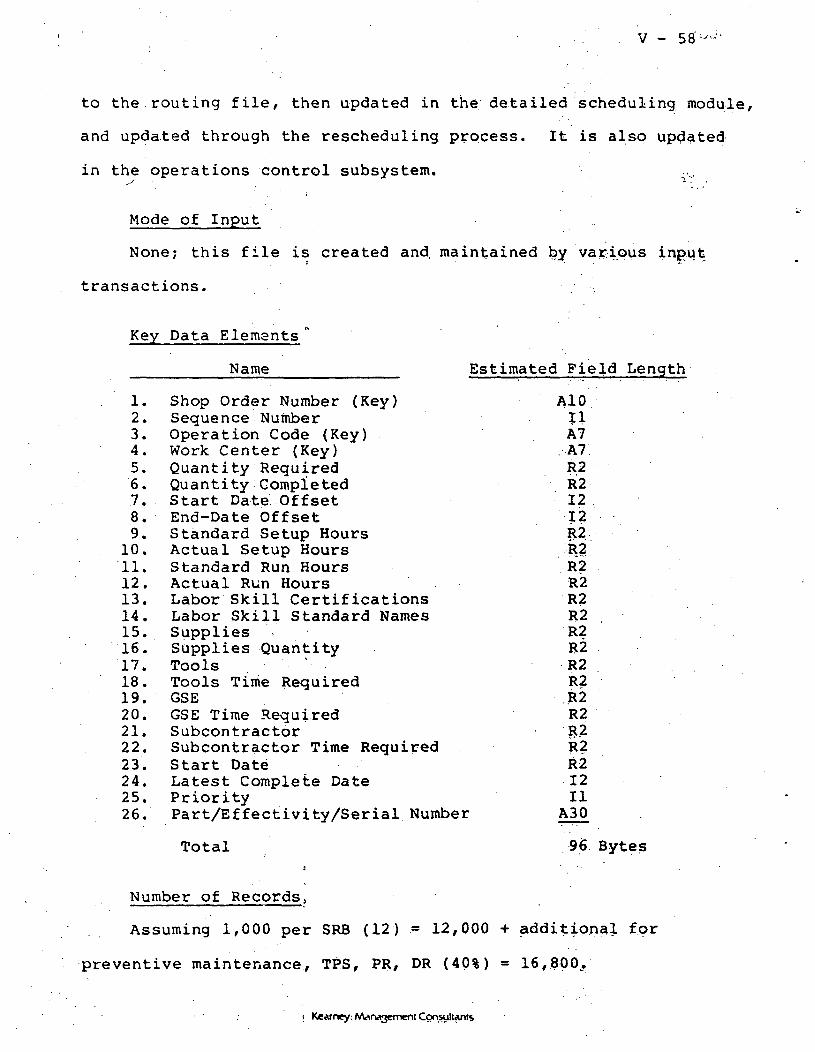
V - 58
to the routing file/ then updated in the detailed scheduling module,
and updated through the rescheduling process. It is also updated
in the operations control subsystem.*S ~* -' _•
Mode of Input
None; this file is created and. maintained by various input
transactions.
Key Data Elements "
Name Estimated Field Length
1. Shop Order Number (Key) AlO2. Sequence Number II3. Operation Code (Key) A74. Work Center (Key) . A75. Quantity Required R26. Quantity Completed R27. Start Date Offset 128. End-Date Offset I?9. Standard Setup Hours R210. Actual Setup Hours R211. Standard Run Hours R?12. Actual Run Hours R2 :13. Labor Skill Certifications R214. Labor Skill Standard Names R215. Supplies \ • R216. Supplies Quantity R217. Tools ' R218. Tools Time Required R219. GSE R220. GSE Time Required R221. Subcontractor R222. Subcontractor Time Required R223. Start Date R224. Latest Complete Date 1225. Priority II26. Part/Effectivity/Serial Number A30
Total 96 Bytess '
Number of Records?
Assuming 1,000 per SRB (12) = 12,000 -f additional for
preventive maintenance, TPS, PR, DR ( 4 0 % ) = 16,800.
i Kearney: A/Unagement Consultants
V - 59
File Size
16,800 x 96 = 1,612,800 bytes = 1.61 MB.
Processing Location
Created within central computer. Modified by USBI/KSC
(Production Control).
Hardware Required
Five CRTs (designated K61 through K65) and one printer
(designated P5) would be required at KSC.
Access Requirements
24 hours per day.
Criticality of Response Time
High.
Security Requirements
High.
Backup Requirements
High.
(v) ResourceSchedule File
Purpose
This file provides data relating to the availability of re-
sources required to work a shop order at the time of prerelease
verification, in order to ascertain that those resources will be
available at the time the shop order is released to the floor.
Kearney: Management Consultants

V - 60
Source
Generated by production scheduling functions.
4
Mode of Input
None; maintained within central computer.
Key Data Elements
Name Estimated Field Length
1. Resource Code (key) AlO
2. Resource Description A30
3. Resource Requirement R2
4. Resource RequirementLoad Factor R2
5. Time Period R2
6. Shop Order Operation AlO
Total 56 Bytes
Number of Records .
80 (one for each resource type) for each time period
(12 per day x 30 days) = 360.
File Size
80 x 360 =28,800 bytes = .029 MB.
Processing Location
Within central computer.
Peripheral Requirements
None.
Kearney: Marvvjement Consultants

. •- V - 61
Access Requirements
24 hours per day.
Security Requirements
High.
Backup Requirements
High.
(w) Resource UsageFile .
Purpose
The purpose of this file is to clock the utilization of
tools, GSE, and other equipment against a shop order.
Source
USBI/KSC (Operations Control).
Mode of Input
CRT.
Kearney: Management Consultants

V -. 62
Estimated Field Length
A15
12
A6
12
12,
I-?
12
A6
AT.
44 Bytes
Key Data Elements
Name
1. Shop Order Number
2. Date
3. Resource Type
4. Date Started
5. Time Started
6. Date Complete
7. Time Complete
8. Work Center
9. Operation Code
Total
Number of Records
Estimated to be 500 per day.
File Size
500 x 30 x 44 = 660,000 bytes = ,66 MB.
Processing Location
Data entered through operations control work centers.
Peripheral Requirements
1 CRT per work center (K18-K59),
Access Requirements
24 hours daily.
Criticality of Response Time
High.
Kearney: Management Consultants

V - 63
Security Requirements
High.
Backup Requirements
High.
(x) ExceptionProcesses AndRework File
Purpose
To create additional shop orders to accommodate additional
work requirements.
Source
USBI/KSC Operations Control.
Mode of Input
CRT.
Key Data Elements
Name Estimated Field Length
1. Shop Order Number (key) A15:
2. Operation Code (key) AIDi
3. Operation Description A30
4. Operation Sequence 12
5. Operation Work Center AID
6. Operation Labor Certifications 5 x A30
7. Operation Resource Requirements 10 x A15
8. Special Notes To Be Determined
To Be Determined
Kearney: Management Consultants

V - 64
Number of Records
To be determined.
File Size
To be determined.
Processing Location
USBI/KSC Process Engineering.
Peripherals Required
5 CRTs (K61-K65) in addition to operations control
work stations.
Access Requirements
High.
Criticality of Response Time
High.
)
Security Requirements
High. .
Backup Requirements . .".
High.
(y) Labor ReportingFile
Purpose
This file is used to report labor against a shop order,
Kearney: Marvtfjement Consultants
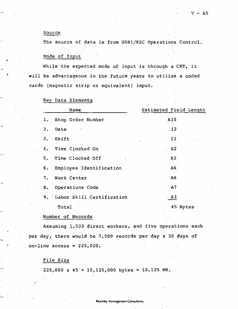
V - 65
Source
The source of data is from USBI/KSC Operations Control.
Mode of Input
While the expected mode of input is through a CRT, it
will be advantageous in the future years to utilize a coded
cards (magnetic strip or equivalent) input.
Key Data Elements
Name Estimated Field Length
1. Shop Order Number A15
2. Date • 12
3. Shift , 12 .
4. Time Clocked On R2
5. Time Clocked Off . R2
6. Employee Identification A6
7. Work Center A6
8. Operations Code A7
9. Labor Skill Certification A3
Total 45 Bytes
Number of Records
Assuming 1,500 direct workers, and five operations each
per day, there would be 7,500 records per day x 30 days of
on-line access = 225,000.
File Size
225,000 x 45 = 10,125,000 bytes = 10.125 MB.
Kearney: Management Consultants
V - 66
Processing Location
USBI/KSC Operations Control.
^Peripheral Requirements
1 CRT per work station (K18-K59).
Access Requirements
24 hours daily.
Criticality.of Reponse. Time
High.
Security Requirements'
High. :
t?
Backup Requirements
Low.
(z) Activity DataFile
Purpose
This file contains summarized activity data beyond the 30
days of detail kept in the APC. It is used in the performance
evaluation subsystem.
Source
Created by Operations Control Subsystem.
Mode of Input
None, created from other files.
Kearney: MArwgenient Consultants

r ; V - . 6.7
Key Data Elements
Name Estimated Field Length
1. Shop Order Number A10
2. Operation Time Log R2
3. Work Center Number A.5
4. Work Center Standard :Duration Time R2
5. Work Center Actual Time R2
6. Labor Certification Number A10
7. Labor Certification StandardTime R2
8. Labor Certification ActualTime R2
9. Supplies Requisitioned A10
10. Supplies Used R2
11. Tools/GSE/Subcontractor A10Number
12. Tools/GSE/SubcontractorStandard Duration Time R2
13. Tools/GSE/SubcontractorActual Time . R2
Total 61 Bytes
Number of Records
To be determined.
File Size
To be determined.
Processing Location
Within central computer.
Kearney: Management Consultants
V -- 6-8"
Peripherals Required
None.
.•
Access Requirements
As Required.
Security Requirements
High.
Backup Requirements
High.
Kearney.- Management. ConsujMrrts

v -
The following table summarizes the file storage requirements,
Table V-l
File Name
Launch Schedule
Major Assembly BOM
Major Assembly Inventory
Major Assembly NewBuild Orders
Major Assembly Refurb
Schedule
Major Assembly GrossRequirements
Summary ResourceRequirements
Summary ResourceAvailability
Major AssemblyManufacturing Orders
Manufacturing BOM
Inventory
Purchasing Order Request
Gross Material Requirements .
Manufacturing Order File
Routings File
Exception ProcessDocuments File
Process ConstraintsFile
P.M. Wort Orders -
Work Ctfnter Capacity
Shop Orders
Resource/Skill Capacity
File Summary
Record Length Number of Records
9 200
44
23
23
21
47
1,295
38
34
60
127
57
47
38
3'3
373
373
172
96
172
30
6,000
100
2,000
6,000
30
4,800
6,000
250,000
600,000
1,000
6,000,000
6,000,000
30,000
4,000
500
2,100
16,800
180
File Size (bytes)
1,800
1,320
138,000
2,300
42,000
28,200
38,850
.182,400
204,000
16,000,000
77,400,000
57,000
276,000,000
228,000,000
11,190,000
1,492,000
To Be Determined
186,500
17,200
1,612,800
30,960
Resource Schedule
Resource Usage
Exception Process andRework
Labor Reporting
Activity Data File
44
45
1,500
225,000
Total
66,000
To Be Determined
10,125,000
To Be Determined
622,816,330 + "TBD"
Kearney: Management Consultants

V - 7'0
EVALUATION OF -EXISTING NASASYSTEMS
A key consideration by the project team was th'e pdss-ibiii'ty
of using existing NASA or USBI systems to perform all or a part
of the-functional requirements .for. th"e',.. Aut6mate'd.-fe.r'ddu'c.t.iSn Con-
trol System.
Accordingly, the project team reviewed the capabilities of
existing NASA and USBI systems to determine whether thds£ systems
should:
1. Be integrated into the APC System arid thu£ perforiti
some portion of its functional requirements, or
2. Interface with the APC System either to perform sdme
APC function or to provide a supporting function td the APC> or
3. Be replaced by the APC System; or
4. Exist coincidehtally with the APC :Systiem for sdme dther
purpose.
The conclusions df the project team follow.
(a) SI MS/SI MS; II
KSC's primary purpose in providing SIMS to its c'dntractots
was twofold: (1) to provide GSA with the ability to review con-
tractor inventory levels; (2) to provide a co'ntrac'tor-integrated
inventory system that may lend itself to contract swapping of
needed inventory.
SIMS is a basic inventory system, processing receipts arid
Kearney: Management Consultants
V - 71
issues of inventory and producing weekly and monthly reports of
inventory status and activity. USBI was the first shuttle con-
tractor to utilize SIMS; however, they utilize it in a "parallel
mode" only and rely on internal systems for actual inventory con-
trol. The system suffers from poor response time/ due in part
to inadequate hardware resource allocation.
Additional difficulties with the system have been noted and
a new set of functional requirements for SIMS II have been issued.
It is anticipated that the current SIMS will be redeveloped and
redeployed using more current hardware and software.
It is not recommended that SIMS or SIMS II be utilized in
place of, or to supplement, the Automated Production Control System
for the following reasons:
1. The inventory records are a key data base in the APC
System; it provides the root record for all part references through-
out the system. There is no satisfactory alternative to providing
an inventory data base which is integrated (with many other records)
in the APC System data base. This file is crucial in design,
accessibility and integrity to the APC System.
2. Due to the criticality of inventory transactions
in the APC system, sufficient processing capacity must be contin-
ually provided to ensure timely processing of the estimated
13,000 transactions per day. NASA/KSC has historically provided
only limited processing capacity to the SIMS application. Failure
to provide adequate processsing capacity in the APC environment
Kearney-. Management Consultants
V - 72
would severely hamper the effectiveness of APC System.
3. There would be no cost savings, since NASA/KSC would
have to develop software, and provide mainframe and peripheral
processing capacity.
4. GSA requirements to review contractor inventories
can be met by the APC System.
(b) AUTOGOSS ,
The AUTOGOSS system is operated at KSC by the Vehicle Opera-
tions Directorate. It is oriented to a task structure, tracing
tasks and requirements in SRB assembly operations. It is a work
control system currently hampered by inadequate hardware capacity,
funding, and technical design.
The system is not an MRP system, in that it does not generate
manufacturing orders based upon material requirements. Once
tasks are input, it does track their status and produces a schedule
(using the given tasks and start and end dates). AUTOGOSS has
achieved 20% of its targeted capabilities. Limited funding
accounts for some of this shortfall.
Future plans called for adding equipment lists, OMI/task
tracking, resource management, configuration management and other
modules.
The AUTOGOSS system represents the closest existing system
to meeting the needs of an APC System. However, the KDMS project
team has suggested that the technical design of AUTOGOSS will not
Kearney: Management Consultants
V - 73
effectively support the additional modules needed for an APC Sys-
tem. If AUTOGOSS is to be expanded in future KSC operations, it
will have to be redeveloped.
Therefore, it is not recommended that AUTOGOSS be used as
the automated production control systems for the following reasons:
1. Since AUTOGOSS would have to be redeveloped to in-
corporate all the features of the APC System described in the
business system design section, the development effort would es-
sentially be developing an APC System from scratch. The disadvan-
tages of this approach have been previously discussed in this
section.
2. It would not be feasible to utilize AUTOGOSS as a
subsystem of the APC System since the development effort to create
a subsystem that integrates with the APC System would be greater
than modifying the existing subsystems in the proposed package to
meet specific requirements.
AUTOGOSS may complement the APC System by being the external
module that handles the scheduling of shared contractor resources.
(c) Kennedy DataManagementSystem (KDMS)
The Kennedy Data Management System (KDMS) is. currently in
the requirements definition phase, which is not expected to be
completed until the summer of 1981. As of January 1981, its
scope had not yet been agreed upon.
It is not contractor specific, but instead focuses on
Kearney: Management Consultants

V - 74 . .
existing KSC systems. USBI management and personnel were not
scheduled for interviews to define their information heeds.
It is not possible to say in what way KDMS could be integrated
with an APC System, since the KDMS requirements have not yet 'bee'n
defined. We anticipate that the final report will recommenci re-
developing most existing KSG systems. This effort will be immense*
both in cost and time. Given the existing uncertainties in this
effort, it is not recommended that KDMS be considered a cost effec-
tive and timely alternative to the recommendation that existing
software be modified to meet USBI's needs.
(d) AutomatedDrawing ReleaseSystems (APRS)
ADRS is a system with a completed set of functional require-
ments as of October 30, 1980.
The system's primary function is to maintain the engineering
data base, and to manage engineering changes applied to that data
base. It is intended to interface with NASA's SCIT and CMA sys-
tems - which provide status accounting and change assurance of
ECNs to NASA. Additionally, ADRS will provide to ACMS the "as
designed" bill of material in order for ACMS to be able to provide
the delta listings (i.e., "as built" versus "as designed"). Thus,*
ADRS is an important function to the APC System.
Rath and Strong, the recommended software vendor, have esti^-
mated three man-months of effort to modify their existing system
i
Kearney: Management Consultants
V - 75
to incorporate the features necessary to produce the reports similar
to those outlined in Section 3.2 of the ADRS functional requirements
document.* It is therefore recommended that many of the ADRS
functions be integrated within the APC System package in so far as
joint requirements of the APC System and NASA reporting are met.
However, two additional factors must be considered. First, NASA
has extremely stringent requirements for configuration and documen-
tation management. An APC System is merely a shop environment
"tool" that does not require much of the massive detail and audit
trail capabilities that ADRS (and ACMS) could provide.
Second, the total installation of the APC System is not
scheduled until the end of 1983 (or beginning 1984). It would ap-
pear that this time frame would not be satisfactory to meet the
short-term needs'of NASA or USBI. As a result, consideration
should be given to treat ADRS and the APC System as two separate
systems (at least for the time being) until a preliminary system
design can further identify timing requirements and opportunities
for possible integration/interface.
(e) AutomatedConfigurationManagementSystems (ACMS)
ACMS tracks part activity history (e.g., installations, re-
movals) and provides a record for the installation of each part
(*) United Space Boosters, Inc., "Functional Requirements forthe Automated Documentation Release System (ADRS)",October 30, *1980.
Kearney: Management Consultants
V - 76
in a SRB (i.e., "as built" configuration). Using the "as -designed"
configuration, it produces a "delta" listing showing all discrep-
ancies between the "as built" versus "as designed". ,';
The system has recently entered production status. Howevesrv
consideration is being given to redesigning the system 'to irVtfl'gr'a'te
it with ADRS. This will eliminate the tedious process of extracting
an "as designed" configuration from the NASA/DRS system.
ACMS also performs a limited inventory function/ keeping track
of receipts, installations, and removals.
The system has significant value in the NASA/USBI SRB
production environment due to its capability to provide a history
for each part and also the "delta" listing of variances between
the "as designed" configuration and the "as built" configuration.
Therefore, it is recommended that modifications to the APG
System include incorporating, but in the short term, not replacing
the capabilities of ACMS for the following reasons:
1. Since ACMS would be redeveloped to be integrated
with ADRS, the cost of incorporating ACMS functions in the APC
System should not represent a cost above the cost of redeveloping"
ACMS.
2. The ACMS data base should be integrated into the
APC System data base to facilitate producing the "delta" listing.
This approach eliminates problems associated with interfacing" two
systems on different computers should ACMS be redeveloped separately
Kearney: Management Consultants
V - 77
(f) Integrated PartsStatus System(IPSS)
IPSS was reviewed for its potential to be the APC System for
USBI. We do not recommend its use for that purpose for the fol-
lowing reasons:
1. It is currently in a development phase with completion
not expected until late 1982. It would be difficult to begin
modification of the package to meet USBI needs until the IPSS
package has accomplished some degree of completion.
2. IPSS is not MRP driven, but is work driven. This
approach was due to the many changes the external tank engineering
data base is experiencing. Also, there are no plans to stock
subassembly inventory levels, or to purchase/manufacture/refurbish
in economic lots.
3. The system does not accommodate automatic back-
scheduling to determine an activity start-date.
4. IPSS does not accommodate labor and tools capacity
planning.
5. Complete user documentation and overall training
programs have not been developed.
6. IPSS does not report the status of critical parts
at vendors.
(g) Material ControlSystem (MCS)
The MCS is primarily a data base which records the inventory
status of all flight hardware. Reports generated include shortage
Kearney: Management Consultants
V - 78/
lists. The system resides in Huntsville and the data from KSC
is mailed to Huntsville.
The system is not sophisticated enough to perform as an APC
function. It would not be desirable to utilize this system as the
Inventory Control System for the APC System, since the APC System
requires inventory data to be integrated into the data base.
Thus, this system will be replaced by the APC System.
(h) Drawing ReleaseSystem (DRS)
The DRS system is operated and maintained by USBI/MSFC. The
system's primary purpose is to store the engineering data base and
subsequent generation breakdown. It is our understanding that this
system will be phased out when NASA/MSFC relinquishes the SRB de-
sign responsibility.
<We do not recommend its use in the APC System since it will be
functionally replaced by the integrated ADRS function.
(i) Project OrientedManagementInformationSystem (PROMIS)
PROMTS is used by USBI to do resource and milestone planning
at the master scheduling level through the use of PERT or critical
path algorithms. Since this module of the master scheduling
subsystem is scheduled for implementation late in the project,
we recommend that PROMIS be retained in a mode external to the
automated production control system. It could be replaced at a
Kearney: Management Consultants
V - 79
later date by a more sophisticated resource planning and operations
budgeting system..
(j) BoosterSimulation Model(BOSIM)_
The BOSIM system is a shuttle program modeling technique for
SRB production requirements, used to approximate the costs of the
full program and to evaluate production policy decisions (e.g.,
spares impact, attrition forecasting).
There is no functional overlap between BOSIM and the APC Sys-
tem; thus neither replaces or can replace the other.
(k) PerformanceMonitoringSystem (PMS) •
The PMS system is intended to evaluate contractor work. It
compares the value of work scheduled with the value of work ac-
complished. It is not being used to measure USBI during the de-
sign development, test and evaluation phase.
The operations budgeting tracking techniques in the automated
production control system will be an upgraded version of the PMS
which could serve USBI's production management as well as NASA's
supervisory requirements. This subsystem will not become opera-
tional until late 1983. Consequently, the PMS system could be
appropriate until that time.
Kearney: Management Consultants

V - 80
(1) Standard ChangeIntegration AndTracking System(SCIT) •
SCIT tracks engineering change notices from conception toi
approval by the board. It then passes this information to the
Configuration Management Accounting system (CMA).
This function was included in the Change Status System (CSS)
of ADRS and will be provided in the APC system. Thus the SCIT
will no longer be necessary when the ADRS features of APC System
becomes operational.
(m) Change ManagementAccounting (CMA)
The CMA system tracks approved engineering change notices
through actual incorporation. These functional requirements were
noted as part of the Change Status System of ADRS, which could be
incorporated in the APC System.
Thus, the CMA system will no longer be required when the
ADRS features of the APC System become operational.
(n) Computer AssistedDrawing (CAD)
The CAD system is a software package used to facilitate
origination and maintenance of engineering drawings. The CAD
system will still be required to produce the necessary graphics,
and neither duplicates or is duplicated by any function in the
APC System.
Kearney: Management Consultants

V - 81
(o) Provisioning System
This system defines the maintenance/support requirements to
engineering drawings and advises what to buy or not to buy to
support an item. Its end purpose will be to develop inventory
level policy, specifically safety stock levels.
It does 'not appear to functionally duplicate or be duplicated
by the APC system. It may be used to determine inventory policy
criteria in the APC System.
(p) Central DataProcessingSystem (CDS)
This system is used by KSC to satisy NASA requirements for
identification of problem areas through capturing problem reports.
This KSC requirement could be met by feeding problem reports into
it from the APC system.
(q) Problem ReportingAnd CorrectiveAction System(PRACA)
The USBI Problem Reporting System receives and stores prob-
lem reports encountered during USBI operations in the SRB assembly
process.
It is recommended that this system continue to function with
an interface with the APC System to provide it with an administrative
record of problem reports. The APC System will capture problem
reports on the shop floor.
Kearney: Management Consultants

V - 82"" -
At a later time, it may be feasible to incorporate the admini-
stration of problem reporting into the APC System.. < .
(r) IBM System 6
This hardware is used for word processing associated with
generating work authorization documents (e.g., OMIs, BOSs).
It neither duplicates or is duplicated by any function in the APC
System. It would be desirable for the APC system to be able to
automatically extract routing resource requirements from the WADs.
The feasibility of this function should be examined in the Detail
Design Phase.
(s) AutomaticCheck-Out (AGO)
This system is used by NASA and USBI for automatic check-out
of shuttle functions and processing of sensor calibration telemetry.
It neither duplicates or is duplicated by any APC function.
CONCEPTUAL .INTEGRATION
Figure V-7 depicts the conceptual integration of the automated
production control system with existing NASA/USBI systems. Thiss
conceptual integration is explained below by system:
1. BOSIM. There is no actual integration or interface
of the APC system with BOSIM. However, it is recognized that both
systems are separately concerned with estimated costs and impacts
of production policy on the launch schedule.
2. PROMIS. PROMIS could receive the major assembly
gross requirements file from the APC System, and process it against
Kearney: Management Consultants

Figure V-7
Automated Production Control System
Conceptual Integration
V - 83
BOSIM
PROVISIONING
SYSTEM 6
MASTERSCHEDULE
MATERIALREQUIREMENTS
PLANNING
A CMS ADRS
CAPACITYREQUIREMENTS
PLANNING
ISHOP FLOORMANAGEMENT
ISHOP FLOORCONTROL
IPERFORMANCEEVALUATION
PROMIS
POPs
"II
CAD
AUTO-GOSS
CDS
PMS _J
Kewney: Management ConsultAnts

V - 84
the summary resource requirements file to. prodi^e res.ouree and
milestone planning reports to the master scheduling subsystem. <•'• c
3. Provisioning. While there may not be a direct f- •
interface between the APC System and the Provisioning system,, theT
Provisioning system can assist in making inventory, policy- decisiems '*
(e.g., safety stock) that can be input to the invento,ry pp.liey/
file of the materials planning requirements subsystem.
4. APRS. ADRS could be functionally integrated into
the APC System to the extent required by the APC System. The
engineering data base could be maintained within the bill o.f
materials module which could maintain both the engineering and
manufacturing bills of material. The bill of materials module
could track current ECN status. A subsystem could be developed to
track milestones (e.g., authorization points, implementation ac^
tivities) of pending/approved ECNs, routing changes, problem
reports, and other items requiring administrative accounting,
5. CAD. The engineering data base in the APC-System
will provide parts lists numbers to the epmputer^aided drawing
function. .
6. AUTOGOSS.' Manufacturing resource re.quiremen.ts
pertaining to contractor-shared GSE equipment could be passed to
AUTOGOSS, if KSC were to agree to use AUTOGOSS for the purpose of >f
scheduling shared GSE equipment. Upon scheduling the equipment, i' ~ j
AUTOGOSS would send the scheduled or nonscheduled requirement *
back to the .APC System. •
7. IBM System 6. While there may be no direct interface
Kearney: Management Consultants

. V - 85
between the word processing equipment responsible for text
maintenance to the work authorization documents, these WADs are
needed on the shop floor at the appropriate times. Prior to
these requirements, the required WADs will be identified, printed,
and distributed to the operations control/dispatch areas.
8. ACMS. ACMS could be integrated into the APC System
data base (to the extent required by the APC system), as a replen-
ishment record for an assembly linked to the requirement record
(explicit pegging) for a component part. Additionally, shop order
routing could be linked to the replenishment record, which would
facilitate tracking of installations, removals, and problem
reports. It could produce the material "delta" listing by comparing
the requirement record generated by the bill of material with the
replenishment record of the part actually installed.
9. CDS/PRACA. Problem reports captured in the shop
floor operations subsystem by the APC System will be interfaced to
the KSC/CDS system and the USBI/PRACA system. No return interface
is required.
10. Performance Monitoring System (PMS). Data required
by the PMS system will be provided by the APC System performance
evaluation subsystem. This will be compared with data provided
by POPs and PROMIS to develop performance reports.
Kearney: Management Consultants


![siqgur pRswid ] jwpu sRI muKvwk pwiqSwhI 10] - Jaap Sahib [Gurmukhi].pdf · nmo srb kwly ] nmo srb idAwly ] nmo srb rUpy ] nmo srb BUpy ]19] nmo srb Kwpy ] nmo srb Qwpy ]](https://img.dokumen.tips/doc/110x75/5f56cad0ac1b37535378eb67/siqgur-prswid-jwpu-sri-mukvwk-pwiqswhi-10-jaap-sahib-gurmukhipdf-nmo-srb.jpg)