Embed Size (px)
Citation preview

Design Report Agile Surface Combatant (ASC)
VT Total Ship Systems Engineering
Trimaran ASC-HI2 Option Ocean Engineering Design Project
AOE 4065/4066 Fall 2003 – Spring 2004 Virginia Tech Team 2
David Cash ___________________________________________ 17147
Gerritt Lang ___________________________________________ 19588
Dorothy McDowell – Team Leader ___________________________________________ 17788
Cory McGraw ___________________________________________ 21514
Scott Patten ___________________________________________ 19592
Joshua Staubs ___________________________________________ 21529

ASC Design – VT Team 2 Page 2
Executive Summary
This report describes the Concept Exploration and Development of an Agile Surface Combatant (ASC) for the United States Navy. This concept design was completed in a two-semester ship design course at Virginia Tech.
The ASC requirement is based on the LCS Flight 0 Preliminary Design Interim Requirements Document and ASC Acquisition Decision Memorandum (ADM). ASC will operate in littoral areas, close-in, depend on stealth, with high endurance and low manning. ASC must perform ISR, MCM, ASW and ASUW missions using interchangeable, networked, tailored modular mission packages built around off-board, unmanned systems. It must support Spartan UCSV’s, VTUAV’s and LAMPS, providing for launch and takeoff, recovery and landing, fueling, maintenance, weapons load-out, planning and control. The VTUAV’s will provide surface, subsurface, shore, and deep inland intelligence, surveillance, reconnaissance (ISR) and electronic warfare. LAMPS will provide Anti-Submarine Warfare (ASW) and Anti-Surface Ship Warfare (ASUW) defense. The UCSV’s can engage surface threats with anti-surface armaments, conduct SAR operations, support and conduct intelligence collection, and conduct surveillance and reconnaissance.
Concept Exploration trade-off studies and design space exploration are accomplished using a Multi-Objective Genetic Optimization (MOGO) after significant technology research and definition. Objective attributes for this optimization are cost (ship acquisition cost and life cycle cost), risk (technology, cost, schedule and performance) and military effectiveness. The product of this optimization is a series of cost-risk-effectiveness frontiers which are used to select the ASC HI2 Baseline Concept Design and define Operational Requirements (ORD1) based on the customer’s preference for cost, risk and effectiveness.
ASC HI2 is the highest-end alternative on the life-cycle cost frontier. This design was chosen to provide a challenging design project using higher risk technology. ASC HI2 characteristics are listed below. ASC HI2 has a wave-piercing tumblehome (WPTH) hullform to reduce radar cross section and improve high speed performance in waves, and a unique moon pool for launching and recovering UCSVs and mine hunting UAVs (RMS). It uses significant automation technology including an automated mess, an Integrated Survivability Management System (ISMS), and watch standing technologies that include GPS, automated route planning, electronic charting and navigation (ECDIS), collision avoidance, and electronic log keeping. Concept Development included hull form development and analysis for intact and damage stability,
structural finite element analysis, IPS system development and arrangement, general arrangements, machinery arrangements, combat system definition and arrangement, seakeeping analysis, cost and producibility analysis and risk analysis. The final concept design satisfies critical operational requirements within cost and risk constraints with additional work required to improve structural and system vulnerability and reduce structural weight.
Ship Characteristic Value LWL 126.3 m Beam 24.9 m Draft 4.2 m D10 10.1 m Lightship weight 2193 MT Full load weight 2825 MT Sprint Speed 42.7 knots Endurance Speed 20 knots Sprint Range 1241 n m Endurance Range 3881 nm
Propulsion and Power 2 LM2500+ engines, 2 225SII Kamewa waterjets, Secondary Integrated Power System (IPS)
BHP 69733 HP Personnel 88 OMOE (Effectiveness) 0.635 OMOR (Risk) 0.691 Ship Acquisition Cost $489M Life -Cycle Cost $877M Combat Systems (Modular and Core)
SSDS, TISS, AN/SPS-73, AN/SLQ-32A(V)3, 2xCIWS, 1xCIGS, 7m
RHIB, AN/SLQ-25 NIXIE, UUV, RMS, MK XII AIMS IFF, Sea
Giraffe AMP Radar UCSVs (Spartan) 2 VTUAVs 3 LAMPS 1

ASC Design – VT Team 2 Page 3
Table of Contents
EXECUTIVE SUMMARY.................................................................................................................................................................. 2
TABLE OF CONTENTS .................................................................................................................................................................... 3
1 INTRODUCTION, DESIGN PROCESS AND PLAN................................................................................................................ 5 1.1 INTRODUCTION.............................................................................................................................................................. 5 1.2 DESIGN PHILOSOPHY, PROCESS, AND PLAN ............................................................................................................. 5 1.3 WORK BREAKDOWN..................................................................................................................................................... 7 1.4 RESOURCES.................................................................................................................................................................... 7
2 MISSION DEFINITION.......................................................................................................................................................... 8 2.1 CONCEPT OF OPERATIONS........................................................................................................................................... 8 2.2 PROJECTED OPERATIONAL ENVIRONMENT (POE) AND THREAT .......................................................................... 8 2.3 ASC OPERATIONS AND MISSIONS.............................................................................................................................. 9 2.4 MISSION SCENARIOS .................................................................................................................................................... 9 2.5 REQUIRED OPERATIONAL CAPABILITIES................................................................................................................. 11
3 CONCEPT EXPLORATION................................................................................................................................................. 12 3.1 STANDARDS AND SPECIFICATIONS........................................................................................................................... 12 3.2 TRADE-OFF STUDIES, TECHNOLOGIES, CONCEPTS AND DESIGN VARIABLES................................................... 12
3.2.1 Hull Form Alternatives...............................................................................................................................12 3.2.2 Sustainability Alternatives..........................................................................................................................16 3.2.3 Propulsion and Electrical Machinery Alternatives................................................................................16 3.2.4 Automation and Manning Parameters.....................................................................................................21 3.2.5 Combat System Alternatives.......................................................................................................................22
3.3 DESIGN SPACE............................................................................................................................................................. 35 3.4 SHIP SYNTHESIS MODEL............................................................................................................................................ 35 3.5 MULTI-OBJECTIVE OPTIMIZATION........................................................................................................................... 37
3.5.1 Overall Measure of Effectiveness (OMOE).............................................................................................38 3.5.2 Overall Measure of Risk (OMOR) ............................................................................................................42 3.5.3 Cost.................................................................................................................................................................43
3.6 OPTIMIZATION RESULTS............................................................................................................................................ 44 3.7 HI2 BASELINE CONCEPT DESIGN ............................................................................................................................. 45
4 CONCEPT DEVELOPMENT (FEASIBILITY STUDY)......................................................................................................... 49 4.1 GENERAL ARRANGEMENT AND COMBAT OPERATIONS CONCEPT (CARTOON)................................................. 49
4.1.1 Mission Operations.....................................................................................................................................50 4.1.2 Machinery Room Arrangements................................................................................................................50
4.2 HULL FORM AND DECK HOUSE ................................................................................................................................ 50 4.2.1 Hullform (Needs Floodable Length Curve).............................................................................................50 4.2.2 Deck House...................................................................................................................................................52
4.3 STRUCTURAL DESIGN AND ANALYSIS..................................................................................................................... 53 4.3.1 Geometry, Components and Materials ....................................................................................................53 4.3.2 Loads..............................................................................................................................................................55 4.3.3 Adequacy.......................................................................................................................................................55
4.4 POWER AND PROPULSION.......................................................................................................................................... 60 4.4.1 Resistance......................................................................................................................................................60 4.4.2 Propulsion.....................................................................................................................................................61 4.4.3 Electric Load Analysis (ELA) ....................................................................................................................64 4.4.4 Fuel Calculation..........................................................................................................................................64
4.5 MECHANICAL AND ELECTRICAL SYSTEMS............................................................................................................. 65 4.5.1 Integrated Power System (IPS) .................................................................................................................66 4.5.2 Service and Auxiliary Systems...................................................................................................................67 4.5.3 Ship Service Electrical Distribution.........................................................................................................67

ASC Design – VT Team 2 Page 4
4.6 MANNING..................................................................................................................................................................... 67
4.6.1 Executive/Administration Department.....................................................................................................69 4.6.2 Operations Department..............................................................................................................................69 4.6.3 Weapons Department..................................................................................................................................69 4.6.4 Engineering Department............................................................................................................................69 4.6.5 Supply Department......................................................................................................................................70
4.7 SPACE AND ARRANGEMENTS.................................................................................................................................... 70 4.7.1 Volume ...........................................................................................................................................................70 4.7.2 Main and Auxiliary Machinery Spaces and Machinery Arrangement...............................................71 4.7.3 Internal Arrangements................................................................................................................................74 4.7.4 Living Arrangements...................................................................................................................................76 4.7.5 External Arrangements...............................................................................................................................78
4.8 WEIGHTS AND LOADING............................................................................................................................................ 78 4.8.1 Weights ..........................................................................................................................................................78 4.8.2 Loading Conditions.....................................................................................................................................79
4.9 HYDROSTATICS AND STABILITY............................................................................................................................... 79 4.9.1 Intact Stability ..............................................................................................................................................80 4.9.2 Damage Stability..........................................................................................................................................82
4.10 SEAKEEPING................................................................................................................................................................. 85 4.11 COST AND RISK ANALYSIS........................................................................................................................................ 89
4.11.1 Cost and Producibility................................................................................................................................89 4.11.2 Risk Analysis.................................................................................................................................................90
5 CONCLUSIONS AND FUTURE WORK............................................................................................................................... 91 5.1 ASSESSMENT................................................................................................................................................................ 91 5.2 FUTURE WORK............................................................................................................................................................ 91 5.3 CONCLUSION ............................................................................................................................................................... 92
REFERENCES ................................................................................................................................................................................. 93
APPENDIX A– ACQUISITION DECISIO N MEMORANDUM........................................................................................................ 94
APPENDIX B– OPERATIONAL REQUIREMENTS DOCUMENT.................................................................................................. 95
APPENDIX C – MACHINERY EQUIPMENT LIST......................................................................................................................... 99
APPENDIX D – WEIGHTS AND CENTERS SUMMARY...............................................................................................................101
APPENDIX E – SPACE AVAILABLE SUMMARY.........................................................................................................................103
APPENDIX F - MATHCAD MODEL ..............................................................................................................................................108

ASC Design – VT Team 2 Page 5
1 Introduction, Design Process and Plan
1.1 Introduction
This report describes the concept exploration and development of an Agile Surface Combatant (ASC) for the United States Navy. The ASC requirement is based on the LCS Flight 0 Preliminary Design Interim Requirements Document (PD-IRD), and Virginia Tech ASC Acquisition Decis ion Memorandum (ADM), Appendix A. This concept design was completed in a two-semester ship design course at Virginia Tech. ASC must perform the following missions using interchangeable, networked, tailored modular mission packages built around off-board, unmanned systems:
1. Intelligence, Surveillance, and Reconnaissance (ISR) 2. Mine Counter Measures (MCM) 3. Anti-Submarine Warfare (ASW) 4. Anti-Surface Ship Warfare (ASuW) 5. Anti-Air Warfare (AAW) self defense
Unmanned systems may include the Spartan Unmanned Combat Surface Vehicle (UCSV) and the Vertical Takeoff Unmanned Air Vehicle (VTUAV), both transformational technologies in development. “Transformation is about seizing opportunities to create new capabilities by radically changing organizational relationships, implementing different concepts of warfighting and inserting new technology to carry out operations in ways that profoundly improve current capabilities and develop desired future capabilities.”
ASC will be capable of performing unobtrusive peacetime presence missions in an area of hostility, and immediately respond to escalating crisis and regional conflict. ASC is likely to be forward deployed in peacetime, conducting extended cruises to sensitive littoral regions. Small crew size and limited logistics requirements will facilitate efficient forward deployment. It will provide its own defense with significant dependence on passive survivability and stealth. As a conflict proceeds to conclusion, ASC will continue to monitor all threats.
The concepts introduced in the ASC design include moderate to high-risk alternatives.
1.2 Design Philosophy, Process, and Plan
The traditional approach to ship design is largely an ‘ad hoc’ process. Experience, design lanes, rules of thumb, preference, and imagination guide selection of design concepts for assessment. Often, objective attributes are not adequately synthesized or presented to support efficient and effective decisions. This project uses a total system approach for the design process, including a structured search of the design space based on the multi-objective consideration of effectiveness, cost and risk.
The scope of this project includes the first two phases in the ship design process, Concept Exploration and Concept Development, as illustrated in Figure 1. The Concept Exploration process is shown in Figure 2. The results of this process are: a preliminary Operational Requirements Document (ORD1) that specifies performance and cost requirements; technology selection; and a baseline concept design with principal characteristics, “one-digit” weights, identification of major HM&E and combat systems, performance predictions and a Class “F” cost estimate. Concept Development follows the more traditional design spiral as illustrated in Figure 3. This process results in a more detailed ship geometry with “two -digit” weights, additional definition of HM&E and combat systems, rough order general arrangements, additional performance prediction and analysis, manning estimate, draft Operational Requirements Document (ORD1), a Preliminary Design Plan, a System Development Plan, and a study report.
In Concept Exploration, the ship design is completed to a level of detail called “Rough Order of Magnitude (ROM)”. It considers those design parameters that have a significant impact on ship balance. The acquisition and design process is normally initiated by a Mission Need Statement (MNS) that includes policy, threat, mission, non-material and material alternatives, and constraints. Specific material alternatives, technologies, and general concepts to be explored are then specified in an Acquisition Decision Memorandum (ADM). The initial ASC project requirement is based on the Littoral Combat Ship (LCS) Interim Requirements Document and ADM, Appendix A. The mission definition is developed from a number of LCS mission presentations (Chapter 2). The naval architect must then translate this general requirement into specific engineering terms, identify specific design alternatives and variables, and specify the design space to be considered for ship synthesis, screening, and optimization. A multiple -objective design optimization is used to search the design space and perform trade-offs. The Agile Surface Combatant (ASC) Concept Exploration considers two types of hull form, the catamaran and the

ASC Design – VT Team 2 Page 6
trimaran. Monohull alternatives are considered in a separate study. It also considers various propulsion systems, combat systems, and automation alternatives using mission effectiveness, risk, and acquisition cost as objective attributes that must be defined mathematically. A ship synthesis model is used to balance these parameters in total ship designs, to assess feasibility and to calculate cost, risk and effectiveness. In more traditional monohull designs, parametric equations may be used in place of physics-based models to speed up the ship synthesis optimization. Because of the unique nature of the ASC Catamaran and Trimaran designs, physics-based analysis must first be used to generate response surface (parametric) models (RSMs) for the ship synthesis model. The final design combinations are ranked by cost, risk, and effectiveness, and presented as a series of non-dominated frontiers. A non-dominated frontier (NDF) represents ship designs in the design space that have the highest effectiveness for a given cost and risk. Concepts for further study and development are chosen from this frontier.
The Concept Development process shown in Figure 3 represents the more traditional design process used in the second stage of this project. A complete circuit around the design spiral is frequently called a Feasibility Study. It investigates each step in the traditional design spiral at a level of detail necessary to demonstrate that assumptions and results obtained in concept exploration are not only balanced, but also feasible. In the process, a second layer of detail is added to the design and risk is reduced.
ConceptExploration
ConceptDevelopment
PreliminaryDesign
ContractDesign
DetailDesign
ExploratoryDesign
Mission orMarketAnalysis
Concept andRequirements
Exploration
TechnologyDevelopment
ConceptDevelopment
and FeasibilityStudiesConcept
BaselineFinalConcept
Figure 1 - Design Process [4]
MNSMission Need
ADM / AOAGeneral
Requirement
Define Design Space
ModelingDOE - Variable Screening & Exploration
RSM
Data
Expert Opinion
Physics-BasedModel
Effectiveness Model
Cost Model
Optimize - Generate
NDFs
Alternative or New
Technology
Ship Aquisition Decision
Alternative Requirement
Definition
ORD1Ship MS1
Technology Acquisition & Development
Ship System Design &
Development
Production Strategy
Ship Aquisition Decision
ORD1Ship MS1
Technology Acquisition & Development
Ship System Design &
Development
Production Strategy
Feasibility & Sensitivity Analysis
Variable Probability
Risk Model
Technology
Figure 2 - Concept Exploration Process [4]

ASC Design – VT Team 2 Page 7
Requirement
Seakeeping
General Arrangements
Weights and Stability
Manning and Automation
Hull Geometry
Resistance and Power
Structures
Mechanical and Electrical
Cost and Effectiveness
Subdiv, Area and Volume
Machinery Arrangements
Figure 3 - Concept Development Design Spiral (Chapter 4) [4]
1.3 Work Breakdown
The ASC Trimaran team consists of six students from Virginia Tech. Each student is assigned areas of work according to his or her interests and special skills as listed in Table 1. This specialization allows members to concentrate efforts on thoroughly understanding a subject. A team leader was also selected to effectively coordinate the efforts of the team. Although each team member had his/her own area of expertise there was generally a great deal of overlap. This is a team effort!
Table 1 - Work Breakdown Name Specialization
Dorothy McDowell (Team Leader) Feasibility, Cost, Risk, Seakeeping David Cash Writer, Effectiveness Gerritt Lang General Arrangements, Machinery Arrangements Cory McGraw Hull Form, Structures, Combat Systems Scott Patten Weights and Stability, Subdivision Joshua Staubs Propulsion and Resistance, Electrical, Manning
and Automation
1.4 Resources
Table 2 - Tools Analysis Software Package
Arrangement Drawings AutoCAD Hull form Development FASTSHIP Hydrostatics FASTSHIP, HECSALV Resistance/Power NavCAD Ship Motions SWAN Ship Synthesis Model MathCad/Model Center/ASSET Structure Model MAESTRO
When software is used, much time and effort is applied to learning and completely understanding the theory behind the input and outputs of each program. In order to ensure our answers make sense, rough order of magnitude calculations are made.

ASC Design – VT Team 2 Page 8
2 Mission Definition
The ASC mission definition is based on the Littoral Combat Ship Flight 0 Preliminary Design Interim Requirements Document (PD-IRD) and ASC Acquisition Decis ion Memorandum (ADM), Appendix A, with elaboration and clarification obtained by discussion and correspondence with the customer, and reference to pertinent documents and web sites referenced in the following sections.
2.1 Concept of Operations
ASC will operate in littoral areas, close-in, depend on stealth, with high speed, minimum external support, and low manning. ASC will contribute to Sea Power 21 and the emerging Global Naval Concept of Operations. It will have tactical employment in future contingency and wartime operations. ASC will rely on modular mission packages built around off-board, unmanned systems. It will provide a Sea Strike basis by performing persistent ISR, enabling forced entry, and engaging in power projection with USMC and Special Operations Forces. It will perform a Sea Shield basis by providing assured access and sea/littoral superiority by conducting MIW, littoral ASW, SUW, ISR, and SOF support mission and supporting homeland defense. ASC will provide Sea Basing by projecting persistent offensive and defensive power, providing security for joint assets and enable sea-based forces with a maneuver and logistics element for joint mobility and sustainment. The Agile Surface Combatant will support the breadth of its mission through the use of interchangeable, networked, tailored mission modules. Table 3 lists ASC modular mission packages and their capabilities.
Table 3 - ASC Modular Packages and their Capabilities Modular Package Modular Mission Capabilities
Mine Counter Measure package
Provide organic punch through capability Search, map, avoid with limited neutralization Support remote & autonomous UV’s and operate helos Massed ASC Division = Dedicated MCM capability
Littoral ASuW package Integrated surface surveillance using on-board/off-board sensors Employ, reconfigure, and support MH-60 series helicopters Conduct SUW Battle Damage Assessment Contribute to and receive the Common Tactical Picture Deploy, control, and recover off-board systems
Littoral ASW package Integrated with multiple off-board sensor systems Automatic on-board processing Helicopter(s) Permits dedicated ASC ASW division
Inherent missions SOF Maneuver, logistics, replenishment NEO MIO Medical, etc.
Mission packages use “plug-in” technology, which interfaces with ASC core support systems. They may require additional “trained” personnel to operate. Packages are built for rapid reconfiguration, are scalable and transportable by air and ship. They will rely on unmanned, distributed off-board systems. Like an “airframe”, visualize ASC as a “sea frame”.
ASC will be capable of performing unobtrusive peacetime presence missions in an area of hostility, and immediately respond to escalating crisis and regional conflict. ASC is likely to be forward deployed in peacetime, conducting extended cruises to sensitive littoral regions. Small crew size and limited logistics requirements will facilitate efficient forward deployment. It will provide its own defense with significant dependence on passive survivability and stealth. As a conflict proceeds to conclusion, ASC will continue to monitor all threats.
2.2 Projected Operational Environment (POE) and Threat
ASC will provide worldwide operation against two distinct classes of threats. These threats include: (1) Threats from nations with a major military capability, or the demonstrated interest in acquiring such a capability. Specific weapons systems that could be encountered include land and surface launched cruise missiles, and significant land based air assets and submarines; and (2) Threats from smaller nations who support, promote, and perpetrate activities that cause regional instabilities detrimental to international security and/or have the potential

ASC Design – VT Team 2 Page 9
development of nuclear weapons. Specific weapons systems include diesel/electric submarines, land-based air assets, chemical/biological/radiological/nuclear weapons, and surface to air missiles (mobile and fixed). Since many potentially unstable nations are located on or near geographically constrained bodies of water, the future tactical picture will be on smaller scales relative to open ocean warfare. Many encounters may occur in shallow water. This increases the difficulty of detecting and successfully prosecuting targets.
Mission modular packages must be able to operate in the following environments:
§ Dense contact and threat environment § Conventional and nuclear weapons environments § Open-ocean (sea states 0 through 8) and littoral regions
2.3 ASC Operations and Missions
ASC operation types include the following: § Integrated with CSG/ESG § Notionally, 2 to 3 ASC ships assigned to each strike group - operational environment drives ASC
configuration § Mission configuration will complement other strike group combatants - provides defense against mine
threat, littoral ASC threat, and small boat threat § Commander determines “tailored” mission configurations – ASC sprint speed results in rapid mission
execution thereby eliminating the threat early on and enabling flow of follow-on forces § ASC Division Operations § Forward deployed, separate from but in support of CSG/ESG § Collective flexibility & versatility while providing mutual support § Maintain a continuous presence in critical theaters of operation § First response capability to anti-access crisis, defeats threats early on § Integrated with Joint Task Force assets to execute access assurance § Rapid reconfiguration to meet mission needs
§ Limited Independent Operations § Inherent (mobility) mission tasking in a known threat environment § Insertion/extraction of Army, USMC, & SOF personnel § Movement of Cargo and Personnel § Logistics support of operations ashore § Replenishment of ASC force § Rapid response to contingency mission tasking
2.4 Mission Scenarios
Mission scenarios for the primary ASC missions are provided in Table 4 through Table 7.
Table 4 - Mine Counter Measures (MCM) Mission Day Mission scenario for MCM
1-21 Small ASC squadron transit from CONUS 21-24 Port call, replenish and load MCM modules 25-30 Conduct mine hunting operations 29 Conduct ASuW defense against small boat threat 31-38 Repairs/Port Call
39 Engage submarine threat for self-defense 41 Engage air threat for self defense 39-43 Conduct mine hunting operations 43 Unrep 44-59 Join CSG/ESG, continue mine hunting and mapping
60+ Port call or restricted availability

ASC Design – VT Team 2 Page 10
Table 5 - Anti-Submarine Warfare (ASW) Mission Day Mission scenario for ASW
1-21 ASC Squadron Transit from CONUS 21-24 Port call, replenish and load ASW modules 25-30 Conduct ASW operations in the littoral area 26 Engage air threat for self defense 27-35 Conduct ISR
36 Unrep 37-42 Sprint to area of hostility 43-50 Support LAMPS operations against submarine threat 43-45 Mine avoidance 47 Engage small boat threat in ASUW self-defense
51 Unrep 52-59 Support LAMPS operations against submarine threat
60+ Port call/restricted availability
Table 6 - Anti-Surface Warfare (ASUW) Mission Day Mission scenario for ASuW
1-21 ASC Transit from CONUS 21-24 Port call, replenish and load ASUW modules 25-30 Conduct ASUW operations in the littoral area
26 Target and engage enemy submarine, ASW self defense 31-35 Support helo operations against surface forces 36 Unrep 37-38 Transit to port 39-42 Changeout/offload modules to support SOF personnel insertion
43-45 Sprint to SOF insertion point 45 Insert SOF Personnel 45-58 Conduct ISR, support SOF 47 Engage air threat for self defense 52 Mine avoidance
57-59 Extract SOF personnel and transit to port 60+ Port call / restricted availability
Table 7 - Independent Operations Scenario Day Mission scenario for Independent Ops
1-21 Transit from CONUS 22 Unrep
23-33 Deliver humanitarian aid, provide support 34-35 Defend against surface threat (ASUW) on return from aid mission 36 Import, load MCM modules 37-58 Conduct mine hunting and mapping 50 Avoid submarine threat (ASW)
56 Engage air threat for self defense 59 Transit to port 60+ Port call / return home

ASC Design – VT Team 2 Page 11
2.5 Required Operational Capabilities
In order to support the missions and mission scenarios described in Section 2.4, the capabilities listed in Table 8 are required. Each of these can be related to functional capabilities required in the ship design, and, if within the scope of the Concept Exploration design space, the ship’s ability to perform these functional capabilities is measured by explicit Measures of Performance (MOPs). ASC will have focused mission capabilities of Mine Warfare (MIW), Littoral Surface Warfare (SUW) against small, highly armed boats, and Littoral Anti-Submarine Warfare (ASW).
Table 8 - List of Critical ASC Required Operational Capabilities (ROCs) ROCs Description
MOB 1 Steam to design capacity in most fuel efficient manner MOB 3 Prevent and control damage MOB 3.2 Counter and control NBC contaminants and agents MOB 5 Maneuver in formation MOB 7 Perform seamanship, airmanship and navigation tasks (navigate, anchor, mooring, scuttle, life boat/raft
capacity, tow/be-towed)
MOB 10 Replenish at sea MOB 12 Maintain health and well being of crew MOB 13 Operate and sustain self as a forward deployed unit for an extended period of time during peace and war
without shore-based support
MOB 16 Operate in day and night environments MOB 17 Operate in heavy weather MOB 18 Operate in full compliance of existing US and international pollution control laws and regulations AAW 1 Provide anti-air defense in cooperation with other forces AAW 1.2 Provide unit self defense AAW 5 Provide passive and soft kill anti-air defense AAW 6 Detect, identify and track air targets AAW 9 Engage airborne threats using surface-to-air armament ASU 1 Engage surface threats with anti-surface armaments ASU 2 Engage surface ships in cooperation with other forces ASU 6 Disengage, evade and avoid surface attack ASW 1 Engage submarines ASW 1.2 Engage submarines at medium range (LAMPS) ASW 1.3 Engage submarines at close range (torpedo) ASW 4 Conduct airborne ASW/recon (LAMPS) ASW 5 Support airborne ASW/recon ASW 10 Disengage, evade, and avoid submarine attack by employing countermeasures and evasion techniques MIW 1 Conduct mine-hunting MIW 4 Conduct mine avoidance MIW 6.7 Maintain magnetic signature limits CCC 3 Provide own unit CCC CCC 4 Maintain data link capability SEW 2 Conduct sensor and ECM operations SEW 3 Conduct sensor and ECCM operations FSO 6 Conduct SAR operations FSO 7 Provide explosive ordnance disposal services FSO 8 Conduct port control functions INT 1 Support/conduct intelligence collection INT 3 Conduct surveillance and reconnaissance NCO 3 Provide upkeep and maintenance of own unit NCO 19 Conduct maritime law enforcement operations

ASC Design – VT Team 2 Page 12
3 Concept Exploration Chapter 3 describes ASC Concept Exploration. Trade-off studies, design space exploration and optimization
are accomplished using a Multi-Objective Genetic Optimization (MOGO).
3.1 Standards and Specifications
The ABS Guide for Building and Classing High Speed Naval Craft will be used as the primary concept design standard. In addition to this requirement, the following standards shall be used as design “guidance”:
§ Stability and Buoyancy: DDS 079-1 (2002) § Endurance Fuel: DDS 200-1 § Electric Load Analysis: DDS 310-1
3.2 Trade-Off Studies, Technologies, Concepts and Design Variables
Available technologies and concepts necessary to provide required functional capabilities are identified and defined in terms of performance, cost, risk and ship impact (weight, area, volume, power). Trade-off studies are performed using technology and concept design parameters to select trade-off options in a multi-objective genetic optimization (MOGO) for the total ship design. Technology and concept trade spaces and parameters are described in the following sections.
3.2.1 Hull Form Alternatives
The ASC hull form must satisfy the following general requirements:
§ Speed of 40 – 50 knots § Transport Factor of 10 – 20 § Displacement of approximately 2000 to 3500 MT § Low cost § Good seakeeping characteristics § Draft of 3-5 meters § Hull Service Life of 20 – 30 years § Support Various Modular Mission Packages
The Transport Factor (TF) provides a non-dimensional relationship between weight, speed, endurance and propulsion power [12]:
WFL = Full load weight of the ship WLS = Light ship weight WFuel = Ship’s fuel weight WCargo = Ship’s cargo or payload weight VS = Sustained speed VE = Endurance speed SHPTI = Total installed shaft horsepower including propulsion and lift systems R = Range at endurance speed SFCE = Specific fuel consumption at endurance speed
Figure 4 displays Transport Factor as a function of speed for a range of hull forms . The red line represents a theoretical limit on TF as a function of speed for displacement ships. Four possible hull form alternatives were selected for ASC using this curve, and based on satisfying the speed requirement (40-50 knots) with at least a modest lift capacity or Transport Factor (10-20). These are:
§ Slender monohull § Catamaran § Trimaran § Surface Effect Ship (SES)

ASC Design – VT Team 2 Page 13
0
10
20
30
40
50
60
0 20 40 60 80 100 120 140
Speed (knots)
Tra
ns
po
rt F
ac
tor
(TF
)
SES
SemiPlaning
Disp
ACV
Planing
2627
28
25
22,2324
19
21
2029
30
Figure 4 - Examples of Transport Factors [12]
Each of the hull form types was assessed based on the ASC requirements with the following conclusions:
§ Conventional Monohull - An optimized conventional monohull form with bow flare is the most traditional design considered. Shipyards have more experience building monohulls and this could improve producibility and reduce construction cost. Monohulls have larger large-object space than most other hull form alternatives for a given displacement. The structural characteristics are well known. Conventional monohulls have a large residuary resistance at high speeds. The radar cross-section for a ship with bow flare and vertical or flared sides may be significant. Compared to multi-hulls there is less usable deck area.
§ Catamaran - The Catamaran or twin-hull concept has been employed in high-speed craft design for several
years. The component hulls (demihulls) usually have V-type sections and a cut-off transom stern. The division of displacement and waterplane area between two relatively slender hulls results in a large deck area, good stability, and smaller roll angles than monohulls of similar displacement under similar sea conditions. However, seakeeping qualities in terms of angle and rate of pitch are poor compared to a monohull. This problem can be reduced using active control of pitching motions. The wetted surface area ratio, slenderness ratio, and hull spacing strongly affect the resistance of a catamaran. The wetted surface area ratio is high compared with planing monohulls of the same displacement. Thus, catamarans have relatively high resistance at low speeds (Fn < 0.35) where skin friction is dominant. At higher speeds, the low wave-making resistance provides low total resistance. Beneficial wave interference can be achieved by the cancellation of part of the divergent wave systems of each demihull. Catamarans have a relatively high radar cross section, especially end-on. The displacement to length ratio is high and the large object volume is relatively low compared to a monohull. The cost for building a catamaran is higher than that for a monohull of the same displacement. U.S. shipyards have little experience in the construction of catamarans.
§ Trimaran - The trimaran hull form consists of a slender monohull with shorter very slender hulls attached to
each side. The trimaran hull form has some advantages over a conventional hull form such as decreased resistance for Froude numbers greater than 0.3, increased stability and more deck area for flight operations. The decreased resistance of the trimaran hull form is important for ASC and the reduced resistance is an advantage for fuel savings. Trimarans could reduce heat signatures by ducting exhausts between the hulls. The radar cross-section of a trimaran is comparable or greater than a conventional monohull or similar displacement. Given that a trimaran has slender hulls, the large-object arrangeable volume is relatively small and limited. The cost of a trimaran would be greater than for a conventional monohull of similar displacement and U.S. shipyards have little to no experience in building trimarans. It is a compromise between monohull and catamaran.
§ Surface Effect Ship (SES) - The SES, or Surface Effect Ship, is a rigid side hulled hovercraft. An SES vessel
can achieve very high speeds while maintaining high transport efficiency. The SES relies on a cushion of air beneath the hull to lift a portion of the hull out of the water, thereby reducing the drag, which results in increased speed. There are, however, several major flaws in this concept. The air under the hull acts as an

ASC Design – VT Team 2 Page 14
undampened spring, resulting in a poor ride when sea waves approach the natural frequency of the vessel. A ride control system is required. In addition, auxiliary motors and fans are required to create the aircushion to lift the vessel out of the water, which adds to the complexity, weight and cost of the ship. Very high speeds are possible on relatively modest propulsion power. Unlike a classic air cushion vehicle, excellent maneuverability is achieved. Reliability and performance in high sea states are major concerns.
Table 9 - Hull Form Advantages (+) / Disadvantages (-)
Low RCS
Low Cost
Resistance at Sustained
Speed
Good Large-Object Spaces
Good Seakeeping Reliability
Conventional Monohull ++ ++ -
Catamaran - - ++ + +
Trimaran - - ++ + ++
Surface Effect Ship (SES) - - ++ - --
Table 9 summarizes the preliminary assessment of hull forms for ASC. The slender monohull was recently
studied by the Center for Innovation in Ship Design (CISD), and the reliability of an SES is somewhat in question because of its dynamic lift system. The catamaran and trimaran were selected for trade-off in our project. The ASC ADM assigns the catamaran to Team 1 and the trimaran to Team 2.
Parametric equations for estimating hull form performance and structural weight are not available for the multihull designs. Analysis is required. To make this task manageable, it was decided to consider only geosims of parent catamaran and trimaran hull forms . A series of hull form variants were created to support Response Surface Modeling (RSM) for estimating structural weight and hull form performance of the geosims as a function of displacement.
A MAESTRO model of the Research Vessel (R/V) Triton, Figure 5, was used as a template for the parent trimaran hull form. A table of offsets was generated from the MAESTRO model and used to create the parent hull form model in FASTSHIP, Figure 6. Patches are created and modified to take the shape of separate sections of the hull form: the centerline hull, the inboard half of the outrigger, the outboard half of the outrigger, and the joiner connecting the outriggers to the centerline hull. The port side is reflected to match the starboard side. Net lines are added after the patches have been shaped to sharpen curvature and to form hard chines. Finally, a transom is added to the stern by creating a vertical patch, merging and trimming to fit.
Figure 5 - MAESTRO Model of the R/V Triton

ASC Design – VT Team 2 Page 15
Figure 6 - Various views of FASTSHIP Parent Trimaran Hull form
Three geosims of the parent hull form were created in FASTSHIP for use in response surface modeling (RSM). Their characteristics are listed in Table 10. Variants were chosen to provide a LBP that could be evenly subdivided with transverse bulkheads and frames. A similar process was followed by Team 1 for the catamaran hull form parent and geosims, Figure 7.
Table 10 - Trimaran Parent Hull form and Geosim Data

ASC Design – VT Team 2 Page 16
Figure 7 - FASTSHIP Parent Catamaran Hull form
3.2.2 Sustainability Alternatives
Sustainability characteristics for ASC include sprint range, endurance range, and provisions storage duration. ASC sprint range goal and threshold values are 1500 nm and 1000 nm. A threshold value of 4000 nm is a typical minimum for surface-combatant endurance range. ASC endurance range goal and threshold values are 4500 nm and 3500 nm, respectively. Provisions and stores duration goal and threshold values for ASC are 24 days and 14 days.
3.2.3 Propulsion and Electrical Machinery Alternatives
3.2.3.1 Machinery Requirements
Based on the ADM and Program Manager guidance, pertinent propulsion plant design requirements are summarized as follows:
General Requirements – The propulsion engines must be non-nuclear, grade A shock certified, and Navy qualified. The machinery system alternatives must span a total power range of 50000–100000 SHP with total ship service power greater than 4000 kW MFLM. The propulsion engines should have a low IR signature, and cruis e/boost options should be considered for high endurance.
Sustained Speed and Propulsion Power – The ship shall be capable of a minimum sustained speed of 40 knots in the full load condition, calm water, and clean hull using no more than 80% of the installed engine rating (maximum continuous rating, MCR) of the main propulsion engine(s) or motor(s), as applicable for mechanical drive plants or electric propulsion plants.
Range and Endurance – The ship shall have sufficient burnable fuel in the full load condition for a minimum range of 3500 nautical miles at 20 knots. The total fuel rate for the propulsion engines and generator sets to be used in determining the endurance fuel requirements shall be calculated using methods described in DDS 200-1. Fuel efficient propulsion options such as ICR gas turbines shall be considered.
Ship Control and Machinery Plant Automation – An integrated bridge system shall be provided in the Navigating Bridge to incorporate integrated navigation, radio communications, interior communications, and ship maneuvering equipment and systems and shall comply with ABS Guide for One Man Bridge Operated (OMBO) Ships. Propulsion control shall be possible from the ship control console (SCC) on the Navigating Bridge and the main control console (MCC) at the Enclosed Operating Station (EOS). In addition to compliance with ABS ACCU requirements for periodically unattended machinery spaces, the machinery centralized control system shall be designed to continuously monitor auxiliary systems, electric plant and damage control systems from the SCC, MCC and Chief Engineer’s office, and control the systems from the MCC and local controllers.
Propulsion Engine and Ship Service Generator Certification – Because of the criticality of propulsion and ship service power to many aspects of the ship’s mission and survivability, this equipment shall be Navy-qualified and Grade-A shock certified.
Temperature and Humidity – Design environmental conditions shall be based on the requirement for extended

ASC Design – VT Team 2 Page 17
vessel operations in the Persian Gulf. Propulsion engine ratings shall be based on the ship operating temperatures listed in Table 11.
Table 11 - Ship Operating Temperatures Condition Summer Winter
Outside Dry Bulb 40 degrees C -18 degrees C Outside Wet Bulb 30 degrees C
Seawater 35 degrees C -2 degrees C
Fuel - The machinery plant shall be designed for continuous operation using distillate fuel in accordance with ASTM D975, Grade 2-D; ISO 8217, F-DMA, DFM (NATO Code F-76 and JP-5 (NATO Code F-44).
3.2.3.2 Machinery Plant Alternatives
Seven machinery plant alternatives are considered in the ASC propulsion trade-off study. These alternatives are shown in Figure 8. The high speed design requires high power density so only gas turbine engines and epicyclic (planetary) reduction gears are considered. Alternatives 1 and 2 are mechanical drive systems with epicyclic gears and Alternatives 3-7 are electric drive systems (IPS). The power requirement is satisfied with 2-4 main engines.
ASC Propulsion
Mechanical Drivew/ Epicyclic Gears
Integrated PowerSystem (IPS)
PSYS = 1Trimaran
2 x 225SII waterjets2 x LM2500+
3 x 3000kw SSGTG
PSYS = 1Catamaran
2 x 225SII waterjets2 x LM2500+
3 x 3000kw SSGTG
PSYS = 2Trimaran
3 x 225SII waterjets3 x LM2500+
3 x 3000kw SSGTG
PSYS = 2Catamaran
4 x 225SII waterjets4 x LM2500+
3 x 3000kw SSGTG
PSYS = 3Trimaran
2 x 225SII waterjets2 x LM2500+
1 x 3000kw SSGTG
PSYS = 3Catamaran
2 x 225SII waterjets2 x LM2500+
1 x 3000kw SSGTG
PSYS = 4Trimaran
3 x 225SII waterjets3 x LM2500+
1 x 2500kw SSDG
PSYS = 4Catamaran
4 x 225SII waterjets3 x LM2500+
1 3000kw SSGTG
PSYS = 5Trimaran
3 x 225SII waterjets2 x LM2500+, 1 x ICR1 x 3000kw SSGTG
PSYS = 5Catamaran
4 x 225SII waterjets2 x LM2500+, 1 x ICR1 x 3000kw SSGTG
PSYS = 6Trimaran
3 x 225SII waterjets4 x LM2500+
1 x 2500kw SSDG
PSYS = 6Catamaran
4 x 225SII waterjets4 x LM2500+
1 3000kw SSGTG
PSYS = 7Trimaran
3 x 225SII waterjets2 x LM2500+, 2 x ICR1 x 3000kw SSGTG
2 main engines 3 main engines 4 main engines
PSYS = 7Catamaran
4 x 225SII waterjets2 x LM2500+, 2 x ICR1 x 3000kw SSGTG
Figure 8 - ASC Machinery Alternatives
Mechanical Drive and IPS systems – Both mechanical drive and IPS systems are considered in the machinery trade-off. Important advantages of a mechanical system are that sub-systems and components are proven in previous Navy ships and cost less than in an IPS system. Mechanical drive systems also weigh less and occupy less volume. The main disadvantage of a mechanical drive system is that it requires a direct in-line connection to the propellers limiting arrangement and location options. Mechanical drive systems are often less efficient than IPS because engine rpm at a given power is governed by the propeller rpm and reduction gear ratio, while engines in an IPS system may be operated at optimum rpm for a given power output. Mechanical drive power can only be used for electrical power if some type of power-take-off system is installed. The main advantages of an IPS system are the ability to locate propulsion engines and generators almost anywhere in the ship, and to provide both propulsion and ship service electrical power. The survivability of the ship also increases with shorter shaft lengths. Another advantage of an IPS system is that it can be used with a traditional fixed pitch propeller or podded propulsion system. The acoustic signature of IPS ships is less because the engines are not connected mechanically to the shaft and fixed pitch propellers have inherently lower signatures and cavitation than CPP. The use of fixed pitch propellers and the ability to run the engines at their maximum efficiency makes IPS systems more efficient. They provide arrangement and operational flexibility, future power growth, improved fuel efficiency and survivability with moderate weight and volume penalties. IPS systems allow easier introduction of new technologies into existing ships. Today’s IPS systems occupy a larger volume and weigh more than most mechanical drive systems.
ASC Design – VT Team 2 Page 18
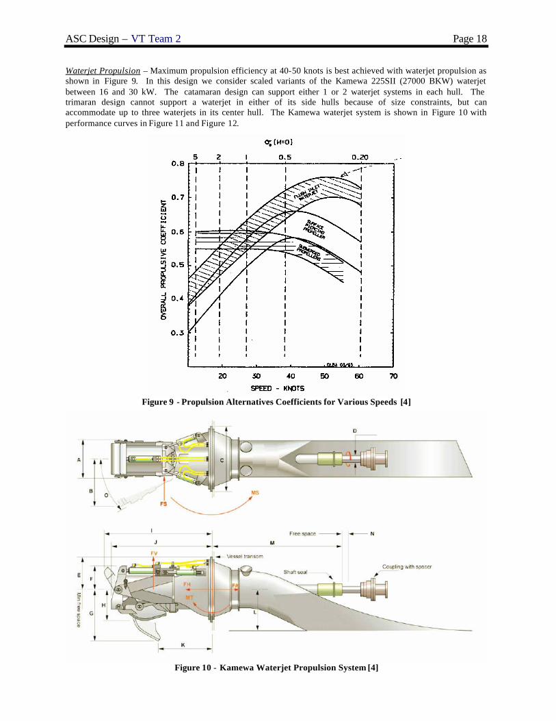
Waterjet Propulsion – Maximum propulsion efficiency at 40-50 knots is best achieved with waterjet propulsion as shown in Figure 9. In this design we consider scaled variants of the Kamewa 225SII (27000 BKW) waterjet between 16 and 30 kW. The catamaran design can support either 1 or 2 waterjet systems in each hull. The trimaran design cannot support a waterjet in either of its side hulls because of size constraints, but can accommodate up to three waterjets in its center hull. The Kamewa waterjet system is shown in Figure 10 with performance curves in Figure 11 and Figure 12.
Figure 9 - Propulsion Alternatives Coefficients for Various Speeds [4]
Figure 10 - Kamewa Waterjet Propulsion System [4]
ASC Design – VT Team 2 Page 19
Figure 11 - Kamewa 225SII Waterjet Power and Thrust Curves [4]
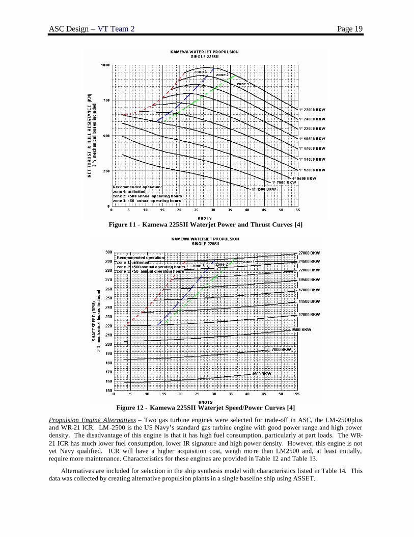
Figure 12 - Kamewa 225SII Waterjet Speed/Power Curves [4]
Propulsion Engine Alternatives – Two gas turbine engines were selected for trade-off in ASC, the LM-2500plus and WR-21 ICR. LM -2500 is the US Navy’s standard gas turbine engine with good power range and high power density. The disadvantage of this engine is that it has high fuel consumption, particularly at part loads. The WR-21 ICR has much lower fuel consumption, lower IR signature and high power density. However, this engine is not yet Navy qualified. ICR will have a higher acquisition cost, weigh mo re than LM2500 and, at least initially, require more maintenance. Characteristics for these engines are provided in Table 12 and Table 13.
Alternatives are included for selection in the ship synthesis model with characteristics listed in Table 14. This data was collected by creating alternative propulsion plants in a single baseline ship using ASSET.

ASC Design – VT Team 2 Page 20
Table 12 - LM-2500 Specifications and Dimensions
Table 13 - ICR Specifications and Dimensions
Table 14 - Propulsion System Alternative Data Propulsion
Option(PSYS)
DescriptionPropulsion
System Type PSYSTYP
Number of Waterjets, Nprop
WaterjetkW
Number of Propulsion
Engines NPENG
Total Brake Propulsion Power PBPENGTOT (kW)
Number of SGs NSSG
SSG Power (ea) KWG(kW)
Endurance Propulsion SFC SFCePE(kg/kwhr)
Sustained Speed Propulsion SFC
SFCsPE(kg/kwhr)
Endurance SSG SFC
SFCeG(kg/kwhr)
Minimum Center Transom Width
at WL wCTrans(m)
Minimum Side Transom Width
at WL wSTrans(m)
Basic Electric Machinery
Weight WBMG(MT)
PSYS=1Trimaran
1
2xLM2500+ 3x3000kw SSGTG
1 2(2 dir)
25 2 52000 3 3000 0.288 0.236 0.29 5.5 0 150.1
1Catamaran
2
2xLM2500+ 3x3000kw SSGTG
1 2 25 2 52000 3 3000 0.288 0.236 0.29 0 3 150.1
2Trimaran
3
3xLM2500+3x3000kw SSGTG
1 3(2 dir)
25 3 78000 3 3000 0.288 0.236 0.29 8 0 150.1
2Catamaran
4
4xLM2500+3x3000kw SSGTG
1 4 25 4 104000 3 3000 0.288 0.236 0.29 0 5.5 150.1
3Trimaran
5
2xLM2500+ 1x3000kw SSGTG
2 2(2 dir)
23 2 52000 2 3000 0.257 0.235 0.257 8 0 107.2
3Catamaran
6
2xLM2500+ 1x3000kw SSGTG
2 2 23 2 52000 2 3000 0.256 0.235 0.256 0 5.5 107.2
4Trimaran
7
3xLM2500+1x3000kw SSGTG
2 3(2 dir)
23 3 78000 2 3000 0.251 0.235 0.251 8 0 107.2
4Catamaran
8
3xLM2500+1x3000kw SSGTG
2 4 18 3 78000 2 3000 0.255 0.235 0.255 0 5.5 107.2
5Trimaran
9
2xLM2500+1xICR
1x3000kw SSGTG
2 3(2 dir)
22 3 74000 2 3000 0.198 0.218 0.198 8 0 107.2
5Catamaran
10
2xLM2500+1xICR
1x3000kw SSGTG
2 4 16 3 74000 2 3000 0.198 0.218 0.198 0 5.5 107.2
6Trimaran
11
4xLM2500+1x3000kw SSGTG
23
(2 dir) 30 4 104000 2 3000 0.257 0.235 0.257 5.5 3 107.2
6Catamaran
12
4xLM2500+1x3000kw SSGTG
2 4 23 4 104000 2 3000 0.257 0.235 0.257 0 5.5 107.2
7Trimaran
13
2xLM2500+2xICR
1x3000kw SSGTG
23
(2 dir) 28 4 96000 2 3000 0.198 0.215 0.198 5.5 3 107.2
7Catamaran
14
2xLM2500+2xICR
1x3000kw SSGTG
2 4 22 4 96000 2 3000 0.198 0.215 0.198 0 5.5 107.2
Ship Service Generator Option – Only a gas turbine generator set is considered because of weight. The gas turbine generator option is the DDA 501-K34. This is the newer version of the DDA 501-K17 with higher power output. This generator is Grade A shock qualified and US Navy certified. It has a high power density. Characteristics for the generator engine are listed in Table 15.

ASC Design – VT Team 2 Page 21
Table 15. DDA 501-K34 Gas Turbine Specifications and Dimensions
3.2.4 Automation and Manning Parameters
To minimize ASC acquisition cost, life cycle cost and personnel vulnerability during combat, it is very important to reduce manning. A number of automation technologies for aircraft and surface vehicle launch and recovery, handling, maintenance, and weapons handling are considered for ASC. Some of the enabling technologies considered are computer/CD-ROM software, GUI’s, large flat panel displays, expert systems, reliable sensors, fiber optics, corrosion and wear-resistant coatings, video teleconferencing, and personal access display devices (PADDs). Some watch standing technologies considered for ASC include GPS, automated route planning, electronic charting and navigation (ECDIS), collision avoidance, and electronic log keeping. Some condition-based maintenance possibilities for ASC include and Integrated Condition Assessment System (ICAS), trend-analysis, expert assistance, and links to Interactive Electronic Tech Manuals (IETMs)/Gold Discs for automated troubleshooting. ASC may include an automated mess, personnel locators/active badges, standard consoles/integrated networks, an Integrated Survivability Management System (ISMS), and training through multimedia. By maintaining most administration and personnel work ashore, ASC will be a paperless ship. Manning will also be reduced through improved preservation methods and materials . Unicoat provides a 300% improvement in life-expectancy, self-priming, 50% reduction in paint time, and 50% reduction in VOC’s. Future technologies not yet available which could be used on ASC include a bridge in the CIC providing large screen displays, 360 degree coverage, and multiple magnification and spectra. Also possible are unmanned machinery spaces that require only a virtual presence and employ IR imaging sensors (through smoke) and robot arms for fire suppression, rigging, and damage control.
In concept exp loration it is difficult to deal with automation manning reductions explicitly, so a ship manning and automation factor is used. This factor represents reductions from “standard” manning levels resulting from automation. The manning factor, CAUTO , varies from 0.5 to 1.0. It is used in the regression based manning equations shown in Figure 13. A manning factor of 1.0 corresponds to a “standard” fully-manned ship. A ship manning factor of 0.5 results in a 50% reduction in manning and implies a large increase in automation. The manning factor is also applied using simple expressions based on expert opinion for automation cost, automation risk, damage control performance and repair capability performance. Manning calculations are shown in Figure 13. A more detailed manning analysis is performed in concept development.
The simple regression-based manning equations are based on the following independent variables: WP : total payload weight VFL : full load hull displacement volume NSSG : number of ship service generators VD : deckhouse volume NPENG : number of propulsion engines VHT : total hull volume The simple regression-based equations calculate the following: NO : number of ship officers NE : number of ship enlisted men NT : total number of ship crew NA : additional accommodations

ASC Design – VT Team 2 Page 22
Figure 13 - ASC-HI2 “Standard” Manning Calculation
3.2.5 Combat System Alternatives
3.2.5.1 MCM
Mine Countermeasures (MCM) includes any activity to prevent or reduce the danger from enemy mines. Passive countermeasures operate by reducing a ship’s acoustic and magnetic signatures, while active countermeasures include mine avoidance, mine-hunting, minesweeping, detection and classification, and mine neutralization. ASC MCM system alternatives are listed in Table 16 and are as follows:
• Mine Avoidance Sonar (Figure 14) – determines the type and presence of mines. MAS is an active MCM that detects mines and allows ASC to avoid dangerous areas. The Multi-Purpose Sonar System VANGUARD is a versatile two frequency active and passive broadband passive sonar system conceived for use on surface vessels to assist navigation and permit detection of dangerous objects. The system is designed primarily to detect mines but will also be used to detect other moving or stationary underwater objects. It can be used as navigation sonar, i.e. as a navigational aid in narrow or dangerous waters. In addition it can complement the sensors onboard anchoring surface vessels with regard to surveillance and protection against divers.
Figure 14 – Mine Avoidance Sonar
• Remote Mine-hunting System (RMS) - The AN/WLD-1 RMS (Figure 15) is an off-board system that will be launched, operated, and recovered from a host surface ship and will employ mine reconnaissance sensors. The RMS is intended to provide battle groups and individual surface combatants with an organic means of detecting and avoiding mines. The remotely operated system, using computer aided detection and precise navigation systems, will detect and classify mines and record their locations for avoidance or subsequent removal. The system, with organic handling, control and logistic support, is designed to be air transportable to forces anywhere in the world. The RMS will provide a rapidly deployable mine countermeasures system to surface combatant forces in the absence of deployable mine countermeasures forces.

ASC Design – VT Team 2 Page 23
Figure 15 – Remote Mine-hunting System (RMS)
• Underwater Unmanned Vehicles (UUVs) - During Operation Iraqi Freedom, the Remus UUV (Figure 16) was able to operate 24 hours a day and verify that the port was mine free.
Figure 16 – REMUS UUV
• ALMDS, AQS-14 and AQS-20 (Figure 17 and Figure 18)- The Airborne Laser Mine Detection System (ALMDS) is an airborne laser system used to detect, localize, and classify near-surface moored and floating mines. The AN/AQS-14A Side-Looking Sonar, or "Q-14 Alpha" as it is commonly called, is an underwater towed body containing a high resolution, side-looking, multi-beam sonar system used for mine-hunting along the ocean bottom. Developed by Northrop Grumman Oceanic Products, this rapidly-deployable system provides real-time sonar images to operators in the aircraft to locate, classify, mark and record mine-like objects and underwater terrain features. The AQS-14A has an active, stabilized underwater vehicle, equipped with advanced multiple-beam side-looking sonar. The MH-53E Sea Dragon helicopter tows the underwater body by a small-diameter electromechanical cable. On board the helicopter, an operator can view the underwater image and identify objects on a video monitor while recording the data on Exabyte AME digital tapes for post mission analysis. Operators actually fly the device underwater, actively controlling the depth or altitude of the device in the water column. Once located, the exact coordinates of mine-like objects can be used by Explosive Ordinance Disposal (EOD) personnel to reacquire and neutralize the mine. The AN/AQS-14A system includes a digital recorder-reproducer, high-resolution 19-inch color video monitor, and a navigation and acoustic control processor. The AN/AQS-20 mine hunting sonar systems will be employed for deeper mine threats. The "Q-20", as it is commonly called, is an underwater towed body containing a high resolution, side-looking, multi-beam sonar system used for mine-hunting along the ocean bottom. This rapidly-deployable system provides real-time sonar images to operators in the aircraft to locate, classify, mark and record mine-like objects and underwater terrain features. The AQS-20 has an active, stabilized underwater vehicle, equipped with advanced multiple-beam side-looking sonar. The MH-53E Sea Dragon helicopter tows the underwater body by a small-diameter electromechanical cable. On board the helicopter, an operator can view the underwater image and identify objects on a video monitor while recording the data on S-VHS digital tapes for post mission analysis. Operators actually fly the device underwater, actively controlling the depth or altitude of the device in the water column. Once located, the exact coordinates of mine-like objects can be used by Explosive Ordinance Disposal (EOD) personnel to reacquire and neutralize the mine.

ASC Design – VT Team 2 Page 24
Figure 17 – AN/AQS-14A Minehunting System
Figure 18 – AN/AQS-20 Minehunting System
• AMDS and RAMICS - The Rapid Airborne Mine Clearance System (RAMICS) is a targeting, fire control, and gun system which fires a supercavitating projectile as a countermeasure against near surface moored mines. The LIDAR and gun system are mounted on the helicopter. The LIDAR directs the gun fire to the target mine. Mine deflagration utilizes reactive material and kinetic energy of the super cavitating projectile.
• OASIS (Figure 19) - The Organic Airborne and Surface Influence Sweep (OASIS) is a self-contained, high speed, shallow water magnetic and acoustic influence sweeping device under development by EDO Corporation. The OASIS towed body is 10 feet long by 20 inches in diameter. It is deployed from the helicopter and provides rapid mine clearance. The OASIS allows for the emulation of the magnetic and acoustic signatures of the platforms in transit through an assault area as well as the conduct of generic minesweeping operations. Designed to operate in shallow waters at speeds up to 40 knots, it can be towed as a single unit or in tandem.
Figure 19 - Organic Airborne and Surface Influence Sweep (OASIS)
• Degaussing - Degaussing is a passive MCM that reduces ASC magnetic signature. Degaussing works by passing a current through a mesh of wires to generate a magnetic field that cancels the ship’s magnetic field as shown in Figure 20.

ASC Design – VT Team 2 Page 25
Figure 20 – Degaussing System
Table 16 - MCM System Alternatives ID MCM System Alternatives 1 (Goal) 2 3 4 (Threshold)
66 NDS 3070 Vanguard - Mine Avoidance Sonar 1 1 1 1 67-73 Remote Minehunting System (RMS) 3 2 2 1 74-77 Small UUV Detachment 1 1 1 1
78 SH-60 MIW Module 1 79-81 EOD Support Modules (or) 1 (or) 1 (or) 1 (or) 1
82 SH-60 ALMDS & AQS-20 Module 1 1 1 1 83 SH-60 AMDS & RAMICS Module 1 1 1 1 84 SINGLE SH-60 OASIS Module (or)1 (or)1 (or)1 (or)1 85 SINGLE SH-60 PUK Module 1 1 1 1
NA Degaussing System NA NA NA NA
3.2.5.2 ASUW
ASC ASUW system alternatives are listed in Table 17 and are as follows:
• AN/SPS-73(V) Radar (Figure 21) - AN/SPS-73(V) is a short-range, two-dimensional, surface-search/navigation radar system. It provides contact range and bearing information. It also enables quick and accurate determination of own ship position relative to nearby vessels and navigational hazards, making it valuable for navigation and defense.
Table 17 - ASUW System Alternatives ID ASuW System Alternatives 1(Goal) 2 3 4 (Threshold)
23 AN/SPS-73 Surface Search Radar 1 1 1 1 24 Thermal Imaging Sensor System (TISS) 1 25 Sea Star SAFIRE II FLIR 1 26 IR Search and Track System (IRST) 1 1 27-30 30mm CIGS Gun 2 1 31-34 57mm MK3 Naval Gun 2 1 35,36,37 7m RHIB 1 1 1 1
Figure 21 – AN/SPS-73(V) Radar
ASC Design – VT Team 2 Page 26
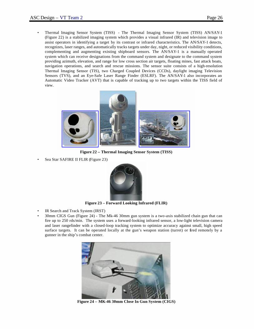
• Thermal Imaging Sensor System (TISS) - The Thermal Imaging Sensor System (TISS) AN/SAY-1 (Figure 22) is a stabilized imaging system which provides a visual infrared (IR) and television image to assist operators in identifying a target by its contrast or infrared characteristics. The AN/SAY-1 detects, recognizes, laser ranges, and automatically tracks targets under day, night, or reduced visibility conditions, complementing and augmenting existing shipboard sensors. The AN/SAY-1 is a manually operated system which can receive designations from the command system and designate to the command system providing azimuth, elevation, and range for low cross section air targets, floating mines, fast attack boats, navigation operations, and search and rescue missions. The sensor suite consists of a high-resolution Thermal Imaging Sensor (TIS), two Charged Coupled Devices (CCDs), daylight imaging Television Sensors (TVS), and an Eye-Safe Laser Range Finder (ESLRF). The AN/SAY-1 also incorporates an Automatic Video Tracker (AVT) that is capable of tracking up to two targets within the TISS field of view.
Figure 22 – Thermal Imaging Sensor System (TISS)
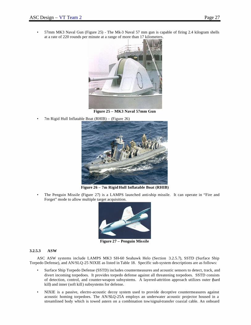
• Sea Star SAFIRE II FLIR (Figure 23)
Figure 23 – Forward Looking Infrared (FLIR)
• IR Search and Track System (IRST) • 30mm CIGS Gun (Figure 24) - The Mk-46 30mm gun system is a two-axis stabilized chain gun that can
fire up to 250 rds/min. The system uses a forward-looking infrared sensor, a low-light television camera and laser rangefinder with a closed-loop tracking system to optimize accuracy against small, high speed surface targets. It can be operated locally at the gun’s weapon station (turret) or fired remotely by a gunner in the ship’s combat center.
Figure 24 – MK-46 30mm Close In Gun System (CIGS)
ASC Design – VT Team 2 Page 27
• 57mm MK3 Naval Gun (Figure 25) - The Mk-3 Naval 57 mm gun is capable of firing 2.4 kilogram shells at a rate of 220 rounds per minute at a range of more than 17 kilometers.
Figure 25 – MK3 Naval 57mm Gun
• 7m Rigid Hull Inflatable Boat (RHIB) – (Figure 26)
Figure 26 – 7m Rigid Hull Inflatable Boat (RHIB)
• The Penguin Missile (Figure 27) is a LAMPS launched anti-ship missile. It can operate in “Fire and Forget” mode to allow multiple target acquisition.
Figure 27 – Penguin Missile
3.2.5.3 ASW
ASC ASW systems include LAMPS MK3 SH-60 Seahawk Helo (Section 3.2.5.7), SSTD (Surface Ship Torpedo Defense), and AN/SLQ-25 NIXIE as listed in Table 18. Specific sub-system descriptions are as follows:
• Surface Ship Torpedo Defense (SSTD) includes countermeasures and acoustic sensors to detect, track, and divert incoming torpedoes. It provides torpedo defense against all threatening torpedoes. SSTD consists of detection, control, and counter-weapon subsystems. A layered-attrition approach utilizes outer (hard kill) and inner (soft kill) subsystems for defense.
• NIXIE is a passive, electro-acoustic decoy system used to provide deceptive countermeasures against acoustic homing torpedoes. The AN/SLQ-25A employs an underwater acoustic projector housed in a streamlined body which is towed astern on a combination tow/signal-transfer coaxial cable. An onboard

ASC Design – VT Team 2 Page 28
generated signal is used by the towed body to produce an acoustic signal to decoy the hostile torpedo away from the ship. The AN/SLQ-25A includes improved deceptive countermeasures capabilities. The AN/SLQ -25B includes improved deceptive countermeasures capabilities, a fiber optic display LAN, a torpedo alert capability and a towed array sensor.
Table 18 - ASW System Alternatives ID ASW System Alternatives 1(Goal) 2(Threshold)
LAMPS MK3 SH-60 Seahawk Helo 3 1 42 SSTD (Surface Ship Torpedo Defense) 1 0 42 AN/SLQ -25 NIXIE 1 1
3.2.5.4 AAW
ASC AAW trade-off alternatives include goal and threshold systems listed in Table 19. The alternatives include: Sea GIRAFFE AMB Radar, SEAPAR Radar, MK XII AIMS IFF, MK 16 CIWS, RAM 8 Cell, RAM 21 Cell, Combined MK 53 SRBOC & NULKA LCHR, Advanced SEW System (AIEWS), and AN/SLQ-32(V)3. All sensors and weapons in each suite are integrated using the Ship Self Defense System (SSDS). This system is intended for installation on all non-Aegis ships. The SSDS improves effectiveness by coordinating hard kill and soft kill and employing them to their optimum tactical advantage. However, SSDS does not improve the performance of any sensor or weapon beyond its stand-alone capability. The SSDS is a versatile system that can be used as a tactical decision aid or an automatic weapon system. SSDS uses mostly Commercial Off-the-Shelf (COTS) products, including a fiber optic Local Area Network (LAN). SSDS employs single or multiple Local Access Unit (LAU) cabinets with an Uninterruptible Power Supply (UPS) and VME card cage. Processor cards are identical and interchangeable, so spares can be stocked.
Table 19 - AAW and SEW System Alternatives ID AAW System Alternatives 1(Goal) 2 3(Threshold)
1 SEA GIRAFFE AMB RADAR 1 2 SEAPAR RADAR - MFR MOUNTED IN DOGHOUSE 1 1 3 MK XII AIMS IFF 1 1 1 4-8 MK 16 CIWS 1 1 1 9-12 RAM 8 Cell 1 13-16 RAM 21 Cell 1 17-22 Combined MK 53 SRBOC & NULKA LCHR 6 6 2 92 Advanced SEW System (AIEWS) 1 1 1 93 AN/SLQ-32(V)3 1 1 1
Specific sub-system descriptions are as follows:
• The Sea GIRAFFE AMB is a state-of-the-art naval multi-function radar using Ericsson's outstanding true 3D Agile Multi-Beam technology. The system functions simultaneously for air surveillance and tracking, surface surveillance and tracking, target indication to weapon systems, and high-resolution splash spotting.
• AN/SLQ -32 Electronic Warfare (EW) System provides warning, identification, and direction-finding of incoming anti-ship cruise missiles (ASCM). It provides early warning, identification, and direction-finding against targeting radars. It also provides jamming capability against targeting radars.
• CIFF (Centralized Id. Friend or Foe) is a centralized, controller processor-based system that associates different sources of target information. It accepts, processes, correlates and combines IFF sensor inputs into one IFF track picture. It controls the interrogations of each IFF system and ultimately identifies all targets as a friend or foe.
• Phalanx Close-In Weapons System (CIWS, Figure 28) provides defense against low altitude ASCMs. It is a hydraulically driven 20 mm gatling gun capable of firing 4500 rounds per minute. CIWS magazine capacity is 1550 rounds of tungsten ammunition. CIWS is computer controlled to automatically correct aim errors. Phalanx Surface Mode (PSUM) incorporates its side mounted Forward Looking Infrared Radar (FLIR) to engage low, slow or hovering aircraft and surface craft.

ASC Design – VT Team 2 Page 29
Figure 28 – MK 16 Close in Weapons System (CIWS)
• Rolling Airframe Missile (RAM, Figure 29) is the threshold missile system. It is cued from SSDS. RAM is a self contained package. It can use Active Optical Target Detector (AOTD) for improved effectiveness in presence of aerosols . RAM also features Infrared Modular Update (IRMU) to provide capability against non-RF radiating threats. It is comprised of the GMLS (launching system) and GMRP (round pack). RAM is effective and lethal against most current ASCMs. Its capability against LAMPS, aircraft, and surface targets is being developed.
Figure 29 – Rolling Airframe Missile (RAM)
• The Decoy Launching System (DLS) Mk 53 (NULKA) is a rapid response Active Expendable Decoy (AED) System capable of providing highly effective defense for ships of cruiser size and below against modern radar homing anti-ship missiles. It is combined with the Super Rapid Bloom Offboard Countermeasures (SRBOC) Chaff and Decoy Launching System that provides decoys launched at a variety of altitudes to confuse a variety of missiles by creating false signals.
Figure 30 – MK53 SRBOC and NULKA

ASC Design – VT Team 2 Page 30
3.2.5.5 SEW
Electronic Warfare system alternatives include AN/SLQ-32 and the AEIWS Advanced SEW System. Descriptions of the specific sub-systems are as follows:
• AN/SLQ -32 is a sensor system that provides early detection and identification of threats. It serves as the electronic eyes of the SSDS. It also provides radar jamming.
• The AN/SLY-2 (V) Advanced Integrated Electronic Warfare System (AIEWS) is the Navy's next -generation shipboard Electronic Warfare (EW) system designed to meet the projected threat in the 2005 to 2010 time frame. The primary functions of AIEWS are detection, correlation, and identification of threat emitters as well as automatic employment of coordinated on-board countermeasures.
3.2.5.6 C4ISR
The Command, Control, Communications, Computers, Intelligence, Surveillance, and Reconnaissance (C4ISR) system includes the alternatives listed in Table 20. Specific sub-system descriptions are as follows:
• The Cooperative Engagement Capability (CEC, Figure 31) is a system of hardware and software that allows the sharing of radar data on air targets among ships. Radar data from individual ships of a Battle Group is transmitted to other ships in the group via a line-of-sight, data distribution system (DDS). Each ship uses identical data processing algorithms resident in its cooperative engagement processor (CEP), resulting in each ship having essentially the same display of track information on aircraft and missiles. An individual ship can launch an anti-air missile at a threat aircraft or anti-ship cruise missile within its engagement envelope, based on track data relayed to it by another ship. Program plans include the addition of E-2C aircraft equipped with CEP and DDS, to bring airborne radar coverage plus extended relay capability to CEC. CEP-equipped units, connected via the DDS network, are known as Cooperating Units (CUs).
Table 20 – C4ISR System Alternatives ID AAW System Alternatives 1(Goal) 3(Threshold)
61,62 ADCON 21 1 1 65 CEC 1 1 63 COMM Suite Level A 1 64 COMM Suite Level B 1
Figure 31 – Cooperative Engagement Capability (CEC)
• Advanced Connectivity (ADCON-21, Figure 32) is the Navy’s newest concept for future distribution for all C4ISR connectivity. It will be designed to have an open architecture, a common computing engineering base, ship-wide integrated information transfer, and system-wide resource management.

ASC Design – VT Team 2 Page 31
Figure 32 – Advanced Connectivity
3.2.5.7 LAMPS
LAMPS (SH-60) alternatives are listed in Table 21. SH-60 Seahawk (Figure 33) can perform ASW, ASUW, search and rescue, SPECOPS, and cargo lift. It also deploys sonobuoys and torpedoes and extends ship’s radar capabilities. It has a retractable in-flight fueling probe for prolonged loitering time. Self defense is provided by two 7.62mm machine guns. It is capable of carrying and launching AGM -114 Hellfire missiles, AGM -119 Penguin missiles, and Mk46 or Mk50 torpedoes.
Table 21 – LAMPS System Alternatives ID LAMPS System Alternatives 1 (Goal) 2 3 (Threshold) 47 SINGLE SH-60 MODULAR DET - 1 HELOS AND HANGAR 1 48 SINGLE SH-60 MODULAR DET - MISSION FUEL 0 49 SINGLE SH-60 MODULAR DET - SUPPORT MOD 1 1 50 SINGLE SH-60 MODULAR DET - SUPPORT MOD 2 1 51 SINGLE SH-60 MODULAR DET - SUPPORT MOD 3 (or) 1 52 SINGLE SH-60 MODULAR DET - SUPPORT MOD 4 (or) 1 53 DUAL SH-60 MODULAR DET - 2 HELOS AND HANGAR 1 54 DUAL SH-60 MODULAR DET - MISSION FUEL 1 55 DUAL SH-60 MODULAR DET - SUPPORT MOD 1 1 56 DUAL SH-60 MODULAR DET - SUPPORT MOD 2 1 57 DUAL SH-60 MODULAR DET - SUPPORT MOD 3 (or) 1 58 DUAL SH-60 MODULAR DET - SUPPORT MOD 4 (or) 1 59 RAST + RAST CONT +HELO CONT 1 1 1 60 AVIATION MAGAZINE - (12) MK46 - (24) HELLFIRE - (6) PENQUIN 1 1 1

ASC Design – VT Team 2 Page 32
Figure 33 – S H-60 Seahawk Helicopter (LAMPS)
3.2.5.8 SPARTAN
SPARTAN system alternatives are listed in Table 22. SPARTAN is shown in Figure 34. SPARTAN can engage surface threats with anti-surface armaments, conduct SAR operations, support and conduct intelligence collection, and conduct surveillance and reconnaissance. It can be equipped with multi-purpose radar, GPS tracking system, video cameras for navigation and control, multiple antennas, side-scan sonar, chemical/bio logical detectors, and weapon systems including a hellfire missile launcher or 7.62mm gatling gun.
Table 22 – SPARTAN System Alternatives ID SPARTAN System Alternatives 1 (Goal) 2 3 (Threshold) 86 1x 11M MODULAR SPARTAN DET USV VEHICLE and STOWAGE 3 2 1 87 1X 11M MODULAR SPARTAN (USV) DET - 1 MAINT MODULE 1 1 1 88 1X 11M MODULAR SPARTAN DET - 1 CONTROL MODULE 1 1 1 89 1X 11M MODULAR SPARTAN DET - 1 MIW SUPPORT MODULE 3 2 1 90 1X 11M MODULAR SPARTAN DET - 1 WEAPON (ASUW) MODULE (or) 3 (or) 2 1 91 MODULAR SPARTAN DET - MISSION FUEL 3 2 1
Figure 34 – Spartan Unmanned Surface Vehicle Core System
3.2.5.9 VTUAV
VTUAV alternatives are listed in Table 23. The VTUAV is shown in Figure 35. The Vertical Take -off Unmanned Aircraft Vehicle (VTUAV) is used in littoral operations both on shore and off. It provides an extension of the ship’s sensors and is suited for high risk missions. VTUAVs are small in size and so can be stored easily onboard. They require very little space for take-off.
Table 23 – VTUAV System Alternatives ID VTUAV System Alternatives 1 (Goal) 0 (Threshold) 38 VTUAV DET - MODULAR - HANGAR AND 3 VEHICLES 1 1 39 VTUAV DET - MODULAR - MAINTENANCE MODULE 1 0 40 VTUAV DET - MODULAR - MISSION COMMAND MODULE 1 1 41 VTUAV DET - MODULAR - MISSION FUEL 1 0

ASC Design – VT Team 2 Page 33
Figure 35 – Vertical Takeoff Unmanned Aircraft Vehicle (VTUAV)
3.2.5.10 Topside Design
In order to minimize radar cross section, ASC alternative technologies may include the following:
• Advanced Enclosed Mast Sensor System is a low RADAR Cross Section (RCS) enclosure that hides ASC’s sensors in one structure as shown in Figure 36. It uses a polarization technique to allow ASC sensor radiation in and out while screening and reflecting enemy sensor radiation. It also protects ASC’s sensors from the environment and provides for 360 degree radiation and sensing without mast blanking.
• The Low Observable Multi Function Stack shown in Figure 37 is another low RCS structure for antennas
and stacks. It incorporates active ventilation to reduce ASC’s heat signature and houses Global Broadcast System (GBS), EHF SATCOM, UHF SATCOM, IMARSAT, Link 11, and Link 16 antennas.
3.2.5.11 Combat Systems Payload Summary
In order to trade-off combat system alternatives with other alternatives in the total ship design, combat system characteristics listed in Table 24 are included in the ship synthesis model data base.
Figure 36 - Advance Enclosed Mast Sensor System [4]

ASC Design – VT Team 2 Page 34
Table 24 - Combat System Ship Synthesis Characteristics ID NAME WTGRP WT (lton) HD10 HAREA DHAREA CRSKW BATKW WARAREA
1 SEA GIRAFFE AMB RADAR 456 2.24 0.00 0.00 9.50 6.96 7.84 AAW2 SEAPAR RADAR - MFR MOUNTED IN DOGHOUSE 456 10.81 1.00 0.00 9.00 117.50 140.00 AAW3 MK XII AIMS IFF 455 2.11 1.00 0.00 0.00 2.70 2.40 AAW4 1X MK 16 CIWS Gun Mount 1 of 5 711 6.34 1.00 0.00 22.45 5.89 15.89 AAW5 1X MK 16 CIWS Local Control 2 of 5 481 0.70 1.00 1.00 0.00 0.00 0.00 AAW6 1X MK 16 CIWS Remote Control 3 of 5 481 0.10 1.00 0.00 0.00 0.44 0.44 AAW7 1X MK 16 CIWS Workshop 4 of 5 482 0.00 1.00 0.00 18.58 0.00 0.00 AAW8 1X MK 16 CIWS 25mm Guns – Ammo 5 of 5 21 4.26 1.00 0.00 12.48 0.00 0.00 AAW9 RAM LAUNCHER - 8 CELL LAUNCHER 1 OF 4 721 2.27 0.00 0.00 0.00 4.80 4.80 AAW
10 RAM LAUNCHER - 8 CELL - CONTROL ROOM 2 OF 4 481 1.13 0.00 0.00 11.34 0.00 0.00 AAW11 RAM LAUNCHER - 8 CELL- 8 READY SERVICE MISSILES 3 OF 4 21 0.86 0.00 0.00 0.00 0.00 0.00 AAW12 RAM LAUNCHER - 8 CELL - 8 RAM MISSILE MAGAZINE 4 OF 4 21 1.02 0.00 0.00 0.00 0.00 0.00 AAW13 RAM LAUNCHER - 21 CELL LAUNCHER 1 OF 4 721 3.22 1.00 0.00 0.00 8.88 8.88 AAW14 RAM LAUNCHER - 21 CELL - CONTROL ROOM 2 OF 4 481 1.36 1.00 0.00 11.34 0.00 0.00 AAW15 RAM LAUNCHER - 21 CELL - 21 READY SERVICE MISSILES 3 OF 4 21 2.24 1.00 0.00 0.00 0.00 0.00 AAW16 RAM LAUNCHER - 21 CELL - 21 RAM MISSILE MAGAZINE 4 OF 4 21 2.68 1.00 0.00 0.00 0.00 0.00 AAW17 2X-MK 137 LCHRs (Combined MK 53 SRBOC & NULKA LCHR) (1 OF 2) 721 0.74 0.00 0.00 21.66 0.00 0.00 AAW18 2X-MK 137 LCHRs Loads (4NULKA, 12 SRBOC) (2 OF 2) 21 0.57 0.00 0.00 0.00 0.00 0.00 AAW19 6X-MK 137 LCHRs (Combined MK 53 SRBOC & NULKA LCHR) (1 OF 2) 721 2.23 1.00 0.00 65.00 0.00 0.00 AAW20 6X-MK 137 LCHRs Loads (12 NULKA, 36 SRBOC) (2 OF 2) 21 1.70 1.00 0.00 0.00 0.00 0.00 AAW21 NULKA Magazine (12 Nulka) 21 0.72 1.00 0.00 3.00 0.00 0.00 AAW22 SRBOC Magazine (200 SRBOC) 21 5.44 1.00 0.00 7.00 0.00 0.00 AAW23 Fwd Surface Search Radar - AN/SPS-73 451 0.24 1.00 0.00 0.00 0.20 0.20 ASUW24 Thermal Imaging Sensor System (TISS) 452 0.13 0.00 0.00 0.00 0.00 0.00 ASUW25 Sea Star SAFIRE II FLIR 452 0.16 0.00 0.00 1.00 0.00 1.50 ASUW26 IR Search and Track System (IRST) 452 1.60 1.00 0.00 19.90 40.00 40.00 ASUW27 1X 30MM CIGS GUN MOUNT 1 of 4 (Close In Gun System) 711 3.47 0.00 11.82 0.00 12.03 36.09 ASUW28 1X 30MM CIGS GUN AMMO STOWAGE 2 of 4 713 0.55 0.00 0.00 0.00 0.00 0.00 ASUW29 1X 30MM CIGS GUN BALLISTIC PROTECTION 3 of 4 164 4.65 0.00 0.00 0.00 0.00 0.00 ASUW30 1X 30MM CIGS GUN AMMO - 2500 ROUNDS 4 of 4 21 2.00 0.00 0.00 0.00 0.00 0.00 ASUW31 57mm MK 3 Naval Gun Mount 1 of 4 711 6.80 2.00 31.00 0.00 4.00 10.00 ASUW32 57mm Stowage 2 of 4 713 2.70 2.00 0.00 0.00 0.00 0.00 ASUW33 57mm Ammo in Gun Mount 120 RDS 3 of 4 21 0.75 2.00 0.00 0.00 0.00 0.00 ASUW34 57mm Ammo in Magazine 880 RDS 4 of 4 21 5.46 2.00 0.00 0.00 0.00 0.00 ASUW35 1X 7M RHIB 583 3.50 1.00 19.01 0.00 0.00 0.00 ASUW36 1X 11M RHIB COMMON LAUNCH-RECOVER SLED 583 1.52 1.00 0.00 0.00 0.00 0.00 ASUW37 1X COMMON LAUNCH-RECOVER ADDED STRUCT (Stern) 185 0.91 1.00 0.00 0.00 0.00 0.00 ASUW38 VTUAV DET - MODULAR - HANGAR AND 3 VEHICLES 23 3.41 0.00 0.00 73.00 0.00 0.00 VTUAV39 VTUAV DET - MODULAR - MAINTENANCE MODULE 26 3.06 0.00 0.00 37.52 0.00 0.00 VTUAV40 VTUAV DET - MODULAR - MISSION COMMAND MODULE 492 3.01 0.00 0.00 37.52 0.00 0.00 VTUAV41 VTUAV DET - MODULAR - MISSION FUEL 42 0.00 0.00 0.00 0.00 0.00 VTUAV42 AN/SLQ-25A (NIXIE) and AN/SLR-24I Towed Array (TRIPWIRE) 473 5.92 1.00 14.30 0.00 6.15 6.15 ASW43 F100 SONAR GROUP 165 165 3.63 1.00 0.00 0.00 0.00 0.00 ASW44 F100 SONAR GROUP 460 460 2.72 1.00 19.40 0.00 45.00 45.00 ASW45 F100 SONAR GROUP 498 498 3.18 1.00 0.00 0.00 0.00 0.00 ASW46 F100 SONAR GROUP 636 636 0.00 1.00 0.00 0.00 0.00 0.00 ASW47 SINGLE SH-60 MODULAR DET - 1 HELOS AND HANGAR 23 9.49 0.00 0.00 88.00 0.00 0.00 LAMPS48 SINGLE SH-60 MODULAR DET - MISSION FUEL 42 0.00 0.00 0.00 0.00 0.00 LAMPS49 SINGLE SH-60 MODULAR DET - SUPPORT MOD 1 26 6.94 0.00 0.00 37.52 0.00 0.00 LAMPS50 SINGLE SH-60 MODULAR DET - SUPPORT MOD 2 26 6.72 0.00 0.00 37.52 0.00 0.00 LAMPS51 SINGLE SH-60 MODULAR DET - SUPPORT MOD 3 26 3.35 0.00 0.00 37.52 0.00 0.00 LAMPS52 SINGLE SH-60 MODULAR DET - SUPPORT MOD 4 26 3.35 0.00 0.00 37.52 0.00 0.00 LAMPS53 DUAL SH-60 MODULAR DET - 2 HELOS AND HANGAR 23 18.98 1.00 427.96 0.00 0.00 0.00 LAMPS54 DUAL SH-60 MODULAR DET - MISSION FUEL 42 3.00 0.00 0.00 0.00 0.00 LAMPS55 DUAL SH-60 MODULAR DET - SUPPORT MOD 1 26 6.94 1.00 0.00 37.52 0.00 0.00 LAMPS56 DUAL SH-60 MODULAR DET - SUPPORT MOD 2 26 6.72 1.00 0.00 37.52 0.00 0.00 LAMPS57 DUAL SH-60 MODULAR DET - SUPPORT MOD 3 26 3.60 1.00 0.00 37.52 0.00 0.00 LAMPS58 DUAL SH-60 MODULAR DET - SUPPORT MOD 4 26 3.35 1.00 0.00 37.52 0.00 0.00 LAMPS59 RAST + RAST CONT +HELO CONT 588 32.38 1.00 16.26 0.00 0.00 0.00 LAMPS60 AVIATION MAGAZINE - (12) MK46 - (24) HELLFIRE - (6) PENQUIN 1 of 2 22 11.22 1.00 0.00 51.75 0.00 0.00 LAMPS61 ADCON 21 - Warfare CDR (-) C/C Suite (DDG 79, 1992) - 1 of 2 411 2.20 1.00 60.00 0.00 62.44 62.44 C4I62 ADCON 21 - Warfare CDR (-) C/C Suite (DDG 79, 1992)-2 of 2 412 6.20 1.00 81.35 0.00 0.00 0.00 C4I63 COMMS SUITE LEVEL A 440 14.53 0.00 65.77 0.00 26.25 32.32 C4I64 COMMS SUITE LEVEL B 440 23.10 1.00 45.72 0.00 36.60 37.20 C4I65 Cooperative Engagement Capability (CEC) 415 1.54 1.00 1.80 2.00 1.60 1.60 C4I66 NDS 3070 Vanguard - Mine Avoidance Sonar 463 0.90 1.00 0.83 0.00 0.00 1.60 MIW67 1X MODULAR RMS - 1 RMS VEHICLE 23 2.72 4.00 19.42 44.00 0.00 0.00 MIW68 1X MODULAR RMS - 1 CONTROL MODULE 476 5.02 1.00 37.52 0.00 0.00 0.00 MIW69 1X MODULAR RMS - 1 MAINT-TRANSP MODULE 26 3.45 1.00 37.52 0.00 0.00 0.00 MIW70 1X MODULAR RMS - 1 TRANSP 1 MODULE 23 3.92 1.00 37.52 0.00 0.00 0.00 MIW71 1X MODULAR RMS - 1 TRANSP 2 MODULE 23 4.33 1.00 37.52 0.00 0.00 0.00 MIW72 1X RMS COMMON LAUNCH-RECOVER SLED 583 1.36 4.00 0.00 0.00 0.00 0.00 MIW73 1X RMS VEHICLE DAVIT 23 2.04 1.00 0.00 0.00 0.00 0.00 MIW74 1X SMALL UUV DET - 3 BPUAV - 5 REMUS 23 0.00 1.00 0.00 0.00 0.00 0.00 MIW75 1X SMALL UUV DET - 1 BATT-RECHARGE MODULE 313 3.41 1.00 37.52 0.00 0.00 0.00 MIW76 1X SMALL UUV DET - 1 CONTROL MODULE 476 2.60 1.00 37.52 0.00 0.00 0.00 MIW77 1X SMALL UUV DET - 1 VEHICLE STOWAGE MODULE 23 7.45 1.00 26.00 0.00 0.00 0.00 MIW78 HELICOPTER MIW MODULE 26 4.56 0.00 0.00 60.50 0.00 0.00 MIW79 TEU - 1X 11M EOD SCULPIN SUPPORT MODULE 29 2.30 1.00 30.25 0.00 0.00 0.00 MIW80 TEU - 1X 11M EOD SUPPORT MODULE 29 4.04 1.00 30.25 0.00 0.00 0.00 MIW81 TEU - 1X 11M EOD SUPPORT MODULE 29 4.04 1.00 30.25 0.00 0.00 0.00 MIW82 TEU - SINGLE SH-60 ALMDS & AQS-20 26 4.30 1.00 0.00 60.50 0.00 0.00 MIW83 TEU - SINGLE SH-60 AMDS & RAMICS 26 5.20 1.00 0.00 60.50 0.00 0.00 MIW84 TEU - SINGLE SH-60 OASIS 26 3.10 1.00 0.00 60.50 0.00 0.00 MIW85 TEU - SINGLE SH-60 PUK MODULE 26 5.90 1.00 0.00 60.50 0.00 0.00 MIW86 1x 11M MODULAR SPARTAN DET USV VEHICLE and STOWAGE 23 10.54 3.00 SPARTAN87 1X 11M MODULAR SPARTAN (USV) DET - 1 MAINT MODULE 26 2.60 1.00 37.52 0.00 0.00 0.00 SPARTAN88 1X 11M MODULAR SPARTAN DET - 1 CONTROL MODULE 495 2.96 1.00 37.52 0.00 2.40 2.40 SPARTAN89 1X 11M MODULAR SPARTAN DET - 1 MIW SUPPORT MODULE 29 3.84 3.00 37.52 0.00 0.00 0.00 SPARTAN90 1X 11M MODULAR SPARTAN DET - 1 WEAPON (ASUW) MODULE 791 2.59 3.00 37.52 0.00 0.00 0.00 SPARTAN91 MODULAR SPARTAN DET - MISSION FUEL 42 4.50 3.00 0.00 0.00 0.00 0.00 SPARTAN92 AIEWS ADVANCED SEW SYSTEM 472 3.00 2.00 40.00 132.00 6.40 6.40 SEW93 AN/SLQ-32(V)3 471 6.13 2.00 4.74 15.70 11.10 29.30 SEW

ASC Design – VT Team 2 Page 35
Figure 37 - Multi-Function Stack [4]
3.3 Design Space
Each ship design is described using 17 design variables (Table 25). Design-variable values are selected by the optimizer from the range indicated and input into the ship synthesis model. The ship is then balanced, checked for feasibility, and ranked based on risk, cost and effectiveness. Hull form alternatives and other hull design parameters (DV1-5) are described in Section 3.2.1. Sustainability alternatives (DV17) and performance measures are described in Section 3.2.2. Propulsion and Machinery alternatives (DV7 and 8) are described in Section 3.2.3. Automation alternatives (DV9) are described in Section 3.2.4. Combat system alternatives (DP 8, 10-16) are described in Section 3.2.5.
3.4 Ship Synthesis Model
A ship synthesis model is required to balance and assess designs selected by the optimizer in the Concept Exploration phase of the design process. Modules in the synthesis model were developed using MathCad software, and the model is integrated and executed in Model Center (MC). The Multi-Objective Genetic Optimization is run in MC using a Darwin optimization plug-in. Figure 38 shows the synthesis model in MC. Measures of Performance (MOPs) are calculated based on the design parameters and their predicted performance in a balanced design. Values of Performance (VOPs), an Overall Measure of Effectiveness (OMOE), Overall Measure of Risk (OMOR), and life cycle cost are also calculated by the synthesis model.
Table 25 - ASC Design Variables (DVs) Description Metric Range
1 Hull form type 1 – catamaran, 2 - trimaran 2 Displacement MT 2000-4000 3 Deckhouse Volume m3 500-2000 4 Hull Material Type alternative 1 – steel, 2 - aluminum 5 Deckhouse Material Type alternative 1 – steel, 2 - aluminum 6 Collective Protection System Type alternative None, partial, full 7 Propulsion System Type alternative 1-7 8 Degaussing System y/n 0,1 9 Manning and Automation Factor ND 0.5 – 1.0 10 MCM Alternative alternative 1 (goal), 2,3,4(threshold) 11 ASUW Alternative alternative 1 (goal), 2,3,4(threshold) 12 AAW Alternative alternative 1 (goal), 2,3(threshold) 13 ASW Alternative alternative 1 (goal), 2(threshold) 14 LAMPS Alternative alternative 1 (goal), 2,3(threshold) 15 VTUAV Alternative y,n 0,1 16 SPARTAN Alternative alternative 1 (goal), 2,3(threshold) 17 Provisions Duration days 14-24

ASC Design – VT Team 2 Page 36
Figure 38 - Ship Synthesis Model in Model Center (MC)
The ship synthesis model is organized into modules as shown in Figure 38: • Input Module - Inputs, decodes and processes the design variable vector and other design parameters that
are constant for all designs. Provides this input to the other modules. • Combat Systems Module - Retrieves combat systems data from the Combat Systems Data Base as
specified by the combat system design variables. Calculates payload SWBS weights, VCGs, areas and electric power requirements and assesses performance for the total combat system.
• Hull form Module - Calculates hull form principal characteristics and supplies them to other modules. It scales the “parent” (baseline) characteristics of the trimaran and catamaran to match the specified displacement and hull form type. It calculates the scaling factor, scales the parent hull characteristics to the daughter hull, adds appendage volumes, and calculates daughter hull characteristics including lengths, areas, and volumes.
• Propulsion Module - Retrieves propulsion system data from the Propulsion System Data Base as specified by the propulsion system design variable. Database generated by modeling similar power plants in ASSET using single baseline design. Data listed in.
• Space Available Module - Calculates available volume and area, minimum depth required at amidships, cubic number, CN, and the height and volume of the machinery box.
• Resistance Module - Calculates hull resistance, sustained speed, and required shaft horsepower at endurance speed and sprint speed. The resistance is calculated using the Holtrop-Mennen regression-based method. It takes the input data of the individual side and center hulls and calculates the resistance for each. It adds the individual hull resistances with a 10% addition for hull interference. The module then calculates the effective bare hull power, appendage drag, and air drag. The propulsive coefficient is approximated. A value of 0.65 is assumed for waterjets. The sustained speed is calculated based on total BHP available with a 25% margin.
• Electric Power Module - Calculates maximum functional electric load with margins (KWMFLM), required generator power (KWGREQ), required average 24-hour electric power (KW24AVG ), and required auxiliary machinery room volume (VAUX). It estimates system power requirements using known values and parametric equations, sums and applies margins, assumes one ship service generator is unavailable, uses a power factor of 0.9, and uses the electric load analysis method from DDS 310-1.
• Weight and Stability Module - Calculates single digit SWBS weights, total weight, fuel weight, and GM/B ratio using parametric equations and known weights. The module uses a combination of known weights and parametric equations to calculate the SWBS weights. KG is calculated from single digit weights and VCGs, estimated using parametric equations. The KM is calculated using geosim scaling of the parent hull KM.
• Tankage Module - Calculates tankage volume requirements based on required sprint and endurance range, and parametric equations. It uses a number of input variables including fluid specific volumes, ballast

ASC Design – VT Team 2 Page 37
type, transmission efficiency, fuel weight, fuel consumption at sprint and endurance speeds, average generator engine fuel consumption, average electric load, sprint and endurance speed, total propulsion engine BHP, potable water weight, and lube oil weight. It uses parametric equations for various tank volumes and design data sheet DDS-200-1 for endurance fuel calculations. It outputs total required tankage volume, fuel tank volume, sprint range and endurance range.
• Space Required Module - Calculates deckhouse arrangeable area required and available, and total ship area required and available using parametric equations. Inputs include number and type of personnel, cubic number, known area requirements, hull and deckhouse volumes, large object volumes, average deck height, beam, and stores duration.
• Feasibility Module - Assesses the overall design feasibility of the ASC. It compares available to required characteristics including total arrangeable ship area, deckhouse area, sustained speed, electrical plant power, minimum and maximum GM/B ratios, endurance range, sprint range, and transom beam.
• Cost Module - Calculates cost using the Naval Surface Warfare Center Carderock Small Fast Ship Cost Calculator. This calculator uses parametric equations for construction costs based on single digit (SWBS) weights, hull type, hull and deckhouse material, propulsion power type, propulsor type, and propulsion power. Fuel and personnel costs are added to calculate life cycle cost. It normalizes costs to the base year (2003) to find discounted life cycle cost. Other life cycle costs are assumed to be the same for all designs. It assumes a service life of 30 years with 3000 steaming hours underway per year. All recurring costs are excluded. The calculator assumes historical costs of modern surface combatants.
• Effectiveness Module - Calculates Values of Performance (VOPs) for sprint range, endurance range, provisions duration, sustained speed, draft, personnel, and RCS using their VOP functions. Inputs combat system VOPs from the combat system module. Calculates the OMOE using these VOPs and their associated weights.
• Risk Module - Calculates a quantitative Overall Measure of Risk (OMOR) for a specific design taking into account performance risk, cost risk, and schedule risk.
3.5 Multi-Objective Optimization
The optimization is performed in Model Center using the Darwin optimization plug-in. Objective attributes for this optimization are life cycle cost, risk (technology cost, schedule and performance risk) and military effectiveness. A flow chart for the Multi-Objective Genetic Optimization (MOGO) is shown in Figure 39. In the first design generation, the optimizer randomly defines 200 balanced ships using the ship synthesis model to balance each ship and to calculate cost, effectiveness and risk. Each of these designs is ranked based on their fitness or dominance in effectiveness, cost and risk relative to the other designs in the population. Penalties are applied for infeasibility and niching or bunching-up in the design space. The second generation of the optimization is randomly selected from the first generation, with higher probabilities of selection assigned to designs with higher fitness. Twenty-five percent of these are selected for crossover or swapping of some of their design variable values. A small percentage of randomly selected design variable values are mutated or replaced with a new random value. As each generation of ships is selected, the ships spread across the effectiveness/cost/risk design space and frontier. After 300 generations of evolution, the non-dominated frontier (or surface) of designs is defined as shown in Figure 46. Each ship on the non-dominated frontier provides the highest effectiveness for a given cost and risk compared to other designs in the design space. The “best” design is determined by the customer’s preferences for effectiveness, cost and risk.
DefineSolution
Space
RandomPopulation
ShipSynthesis
Feasible?
Niche?
Fitness -Dominance
Layers
SelectionCrossoverMutation
Risk
Cost
Figure 39 - Multi-Objective Genetic Opti mization

ASC Design – VT Team 2 Page 38
In order to perform the optimization, quantitative objective functions are developed for each objective attribute. Effectiveness and risk are quantified using overall measures of effectiveness and risk developed as illustrated in Figure 40 and described in Sections 3.5.1 and 3.5.2. Life Cycle Cost (LCC) is calculated using the Naval Surface Warfare Center Carderock Small Fast Ship Cost Calculator.
MissionDescription
OMOE Hierarchy
ROCs
Requirements and constraints for all
designs
MOPs,Goals &
Thresholds
DPs
VOPFunctions
OMOEFunction
MOPweights
MAVT
AHP
OMOR Hierarchy
Cost Model
Tentative Schedule
AHP
OMOR Weights
OMOR Function
Probabilities and
Consequences
Risk Index
Figure 40 - OMOE and OMOR Development Process
3.5.1 Overall Measure of Effectiveness (OMOE)
Figure 40 illustrates the process used to develop the ASC OMOE and OMOR. Important terminology used in describing this process includes:
• Overall Measure of Effectiveness (OMOE) - Single overall figure of merit index (0-1.0) describing ship effectiveness over all assigned missions or mission types
• Mission or Mission Type Measures of Effectiveness (MOEs) - Figure of merit index (0-1.0) for specific mission scenarios or mission types
• Measures of Performance (MOPs) - Specific ship or system performance metric independent of mission (speed, range, number of missiles)
• Value of Performance (VOP) - Figure of merit index (0-1.0) specifying the value of a specific MOP to a specific mission area for a specific mission type. There are a number of inputs which must be integrated when determining overall mission effectiveness in a
naval ship: 1) defense policy and goals; 2) threat; 3) existing force structure; 4) mission need; 5) mission scenarios; 6) modeling and simulation or war gaming results; and 7) expert opinion. Ideally, all knowledge about the problem could be included in a master war-gaming model to predict resulting measures of effectiveness for a matrix of ship performance inputs in a series of probabilistic scenarios. Regression analysis could be applied to the results to define a mathematical relationship between input ship MOPs and output effectiveness. The accuracy of such a simulation depends on modeling the detailed interactions of a complex human and physical system and its response to a broad range of quantitative and qualitative variables and conditions including ship MOPs. Many of the inputs and responses are probabilis tic so a statistically significant number of full simulations must be made for each set of discrete input variables. This extensive modeling capability does not yet exist for practical applications.
An alternative to modeling and simulation is to use expert opinion directly to integrate these diverse inputs, and assess the value or utility of ship MOPs in an OMOE function [1]. This can be structured as a multi-attribute decision problem. Two methods for structuring these problems dominate the literature: Multi-Attribute Utility Theory and the Analytical Hierarchy Process. In the past, supporters of these theories have been critical of each other, but recently there have been efforts to identify similarities and blend the best of both for application in Multi-Attribute Value (MAV) functions. This approach is adapted here for deriving an OMOE.
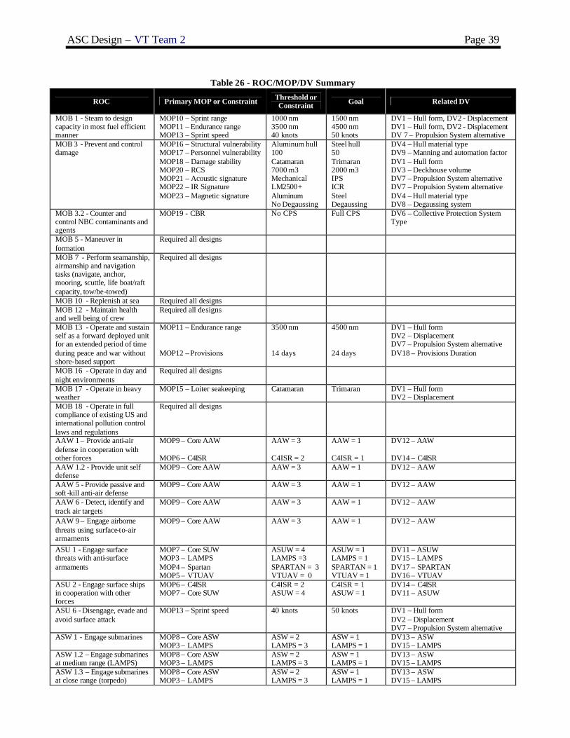
ASC Design – VT Team 2 Page 39
Table 26 - ROC/MOP/DV Summary
ROC Primary MOP or Constraint Threshold or Constraint Goal Related DV
MOB 1 - Steam to design capacity in most fuel efficient manner
MOP10 – Sprint range MOP11 – Endurance range MOP13 – Sprint speed
1000 nm 3500 nm 40 knots
1500 nm 4500 nm 50 knots
DV1 – Hull form, DV2 - Displacement DV1 – Hull form, DV2 - Displacement DV 7 – Propulsion System alternative
MOB 3 - Prevent and control damage
MOP16 – Structural vulnerability MOP17 – Personnel vulnerability MOP18 – Damage stability MOP20 – RCS MOP21 – Acoustic signature MOP22 – IR Signature MOP23 – Magnetic signature
Aluminum hull 100 Catamaran 7000 m3 Mechanical LM2500+ Aluminum No Degaussing
Steel hull 50 Trimaran 2000 m3 IPS ICR Steel Degaussing
DV4 – Hull material type DV9 – Manning and automation factor DV1 – Hull form DV3 – Deckhouse volume DV7 – Propulsion System alternative DV7 – Propulsion System alternative DV4 – Hull material type DV8 – Degaussing system
MOB 3.2 - Counter and control NBC contaminants and agents
MOP19 - CBR No CPS Full CPS DV6 – Collective Protection System Type
MOB 5 - Maneuver in formation
Required all designs
MOB 7 - Perform seamanship, airmanship and navigation tasks (navigate, anchor, mooring, scuttle, life boat/raft capacity, tow/be-towed)
Required all designs
MOB 10 - Replenish at sea Required all designs MOB 12 - Maintain health and well being of crew
Required all designs
MOB 13 - Operate and sustain self as a forward deployed unit for an extended period of time during peace and war without shore-based support
MOP11 – Endurance range MOP12 – Provisions
3500 nm 14 days
4500 nm 24 days
DV1 – Hull form DV2 – Displacement DV7 – Propulsion System alternative DV18 – Provisions Duration
MOB 16 - Operate in day and night environments
Required all designs
MOB 17 - Operate in heavy weather
MOP15 – Loiter seakeeping Catamaran Trimaran DV1 – Hull form DV2 – Displacement
MOB 18 - Operate in full compliance of existing US and international pollution control laws and regulations
Required all designs
AAW 1 – Provide anti-air defense in cooperation with other forces
MOP9 – Core AAW MOP6 – C4ISR
AAW = 3 C4ISR = 2
AAW = 1 C4ISR = 1
DV12 – AAW DV14 – C4ISR
AAW 1.2 - Provide unit self defense
MOP9 – Core AAW AAW = 3 AAW = 1 DV12 – AAW
AAW 5 - Provide passive and soft -kill anti-air defense
MOP9 – Core AAW AAW = 3 AAW = 1 DV12 – AAW
AAW 6 - Detect, identify and track air targets
MOP9 – Core AAW AAW = 3 AAW = 1 DV12 – AAW
AAW 9 – Engage airborne threats using surface-to-air armaments
MOP9 – Core AAW AAW = 3 AAW = 1 DV12 – AAW
ASU 1 - Engage surface threats with anti-surface armaments
MOP7 – Core SUW MOP3 – LAMPS MOP4 – Spartan MOP5 – VTUAV
ASUW = 4 LAMPS =3 SPARTAN = 3 VTUAV = 0
ASUW = 1 LAMPS = 1 SPARTAN = 1 VTUAV = 1
DV11 – ASUW DV15 – LAMPS DV17 – SPARTAN DV16 – VTUAV
ASU 2 - Engage surface ships in cooperation with other forces
MOP6 – C4ISR MOP7 – Core SUW
C4ISR = 2 ASUW = 4
C4ISR = 1 ASUW = 1
DV14 – C4ISR DV11 – ASUW
ASU 6 - Disengage, evade and avoid surface attack
MOP13 – Sprint speed 40 knots 50 knots DV1 – Hull form DV2 – Displacement DV7 – Propulsion System alternative
ASW 1 - Engage submarines MOP8 – Core ASW MOP3 – LAMPS
ASW = 2 LAMPS = 3
ASW = 1 LAMPS = 1
DV13 – ASW DV15 – LAMPS
ASW 1.2 – Engage submarines at medium range (LAMPS)
MOP8 – Core ASW MOP3 – LAMPS
ASW = 2 LAMPS = 3
ASW = 1 LAMPS = 1
DV13 – ASW DV15 – LAMPS
ASW 1.3 – Engage submarines at close range (torpedo)
MOP8 – Core ASW MOP3 – LAMPS
ASW = 2 LAMPS = 3
ASW = 1 LAMPS = 1
DV13 – ASW DV15 – LAMPS

ASC Design – VT Team 2 Page 40
ROC Primary MOP or Constraint Threshold or Constraint Goal Related DV
ASW 4 - Conduct airborne ASW/recon (LAMPS)
MOP8 – Core ASW MOP3 – LAMPS MOP6 – C4ISR
ASW = 2 LAMPS = 3 C4ISR = 2
ASW = 1 LAMPS = 1 C4ISR = 1
DV13 – ASW DV15 – LAMPS DV14 – C4ISR
ASW 5 – Support airborne ASW/recon
MOP3 – LAMPS MOP6 – C4ISR
LAMPS = 3 C4ISR = 2
LAMPS = 1 C4ISR = 1
DV15 – LAMPS DV14 – C4ISR
ASW 10 – Disengage, evade and avoid submarine attack by employing countermeasures and evasion techniques
MOP8 – Core ASW MOP13 – Sprint Speed MOP10 – Sprint Range
ASW = 2 40 knots 1000 nm
ASW = 1 50 knots 1500 nm
DV13 – ASW DV1 – Hull form DV2 – Displacement DV7 – Propulsion System alternative
MIW 1 – Conduct mine-hunting
MOP1 – Core MCM MOP2 – MCM Modules MOP3 – LAMPS MOP4 – Spartan MOP5 – VTUAV MOP6 – C4ISR
MCM = 4
MCM = 1 DV10 – MCM DV15 – LAMPS DV17 – Spartan DV16 – VTUAV DV14 – C4ISR
MIW 4 – Conduct mine avoidance
MOP1 – Core MCM MCM = 4 MCM = 1 DV10 – MCM
MIW 6.7 – Maintain magnetic signature limits
MOP 23 – Magnetic Signature Steel No
Aluminum Yes
DV4 – Hull Material type DV 8 – Degaussing System
CCC 3 - Provide own unit CCC
MOP6 – C4ISR C4ISR = 2 C4ISR = 1 DV14 – C4ISR
CCC 4 - Maintain data link capability
MOP6 – C4ISR C4ISR = 2 C4ISR = 1 DV14 – C4ISR
SEW 2 - Conduct sensor and ECM operations
Required all designs AAW = 2 AAW = 2 DV12 – AAW
SEW 3 – Conduct sensor and ECCM operations
Required all designs AAW = 2 AAW = 2 DV12 – AAW
FSO 6 - Conduct SAR operations
MOP3 – LAMPS MOP4 – Spartan MOP5 – VTUAV
LAMPS =3 SPARTAN = 3 VTUAV = 0
LAMPS = 1 SPARTAN = 1 VTUAV = 1
DV15 – LAMPS DV17 – SPARTAN DV16 – VTUAV
FSO 7 – Provide explosive ordnance disposal services
MOP2 – MCM Modules MCM = 4 MCM = 1 DV10 – MCM
FSO 8 – Conduct port control functions
MOP13 – Sprint speed MOP14 – Draft
40 knots 5.5 meters
50 knots 3 meters
DV1 – Hull form DV2 – Displacement DV7 – Propulsion System alternative
INT 1 - Support/conduct intelligence collection
MOP3 – LAMPS MOP4 – Spartan MOP5 – VTUAV
LAMPS =3 SPARTAN = 3 VTUAV = 0
LAMPS = 1 SPARTAN = 1 VTUAV = 1
DV15 – LAMPS DV17 – SPARTAN DV16 – VTUAV
INT 3 - Conduct surveillance and reconnaissance (ISR)
MOP3 – LAMPS MOP4 – Spartan MOP5 – VTUAV MOP6 – C4ISR
LAMPS =3 SPARTAN = 3 VTUAV = 0 C4ISR = 2
LAMPS = 1 SPARTAN = 1 VTUAV = 1 C4ISR = 1
DV15 – LAMPS DV17 – SPARTAN DV16 – VTUAV DV14 – C4ISR
NCO 3 - Provide upkeep and maintenance of own unit
Required all designs
NCO 19 - Conduct maritime law enforcement operations
MOP13 – Sprint speed MOP14 – Draft
40 knots 5.5 meters
50 knots 3 meters
DV1 – Hull form DV2 – Displacement DV7 – Propulsion System alternative
The process described in Figure 40 begins with the Mission Need Statement and mission description. Required capabilities (ROCs) are identified to perform the ship’s mission(s) and measures of performance (MOPs) are specified for those capabilities that will vary in the designs as a function of the ship design variables (DVs). Each MOP is assigned a threshold and goal value. Required capabilities and applicable restraints to all designs are also specified.
Table 26 summarizes the ROCs, DV and MOPs definition for ASC. An Overall Measure of Effectiveness (OMOE) hierarchy is developed for the MOPs using the Analytical Hierarchy Process (AHP) to calculate MOP weights and Multi-Attribute Value Theory (MAVT) to develop individual MOP value functions. The result is a weighted overall effectiveness function (OMOE) that is used as one of three objectives in the multi-objective optimization. In the AHP, pair-wise comparison questionnaires are produced to solicit expert and customer opinion, required to calculate AHP weights. Value of Performance (VOP) functions (generally S-curves) are developed for each MOP and VOP values are calculated using these functions in the ship synthesis model. A particular VOP has a value of zero corresponding to the MOP threshold, and a value of 1.0 corresponding to the MOP goal.

ASC Design – VT Team 2 Page 41
Figure 41 - OMOE Hierarchy
Table 27 - MOP Table
Figure 41 illustrates the OMOE hierarchy for ASC derived from
Table 26. Separate hierarchies are developed for each type of mission for ASC. MOPs are grouped into five categories (mission and active defense, sustainability, mobility, vulnerability, and susceptibility) under each mission. MOPs are listed in Table 27. MOP weights are calculated using expert opinion and pair wise comparison as shown in Figure 42. Results are shown in Figure 43. A typical ASC VOP curve (for sprint (sustained) speed, MOP 13) is illustrated in Figure 44. Other VOP curves and functions are similar. MOP weights and value functions are finally assembled in a single OMOE function:

ASC Design – VT Team 2 Page 42
( )[ ] ( )iii
iii MOPVOPwMOPVOPgOMOE ∑==
Figure 42 - AHP Pairwise Comparison
Figure 43 - MOP Weights
0
0.1
0.2
0.3
0.4
0.5
0.6
0.7
0.8
0.9
1
40 41 42 43 44 45 46 47 48 49 50
VS (knots)
VOP13(VS)
Figure 44 - Value of Performance Function for Sprint (Sustained) Speed
3.5.2 Overall Measure of Risk (OMOR)
The naval ship concept design process often embraces novel concepts and technologies that carry with them an inherent risk of failure simply because their application is the first of its kind. This risk may be necessary to achieve specified performance or cost reduction goals.
Three types of risk events are considered in the ASC risk calculation: performance, cost and schedule. The initial assessment of risk performed in Concept Exploration, as illustrated in Figure 40, is a very simplified first step in the overall Risk Plan and the Systems Engineering Management Plan (SEMP) for ASC. Referring to Figure

ASC Design – VT Team 2 Page 43
40, after the ship’s missions and required capabilities are defined and technology options identified, these options and other design variables are assessed for their potential contribution to overall risk. MOP weights, tentative ship and technology development schedules and cost predictions are also considered. Calculating the OMOR first involves identifying risk events associated with specific design variables, required capabilities, cost, and schedule. The Risk is calculated for each event and a risk table or register is created. Possible risk events identified for ASC are listed in Table 28. Some possible performance risk events are MCM, Spartan, or VTUAV systems fail to perform as predicted, structural failure from transverse loading, aluminum material problems, poor seakeeping performance, poor resistance estimate, and poor IPS reliability or performance. Cost and schedule risk events include IPS or automation exceeding cost or development schedule estimates. The AHP and expert pair-wise comparison are then used to calculate OMOR hierarchy weights, Wperf, Wcost, Wsched, wj and wk. The OMOE performance weights calculated previously that are associated with risk events are normalized to a total of 1.0, and reused for calculating the OMOR. Once possible risk events are identified, a probability of occurrence, Pi, and a consequence of occurrence, Ci, are estimated for each event using Table 29 and Table 30. The OMOR is calculated using these weights and probabilities in Equation 3-2:
kkk
kschedjjj
jtiii
ii
iperf CPwWCPwWCP
ww
WOMOR ∑∑∑ ∑++= cos
Once the OMOR variables have been determined, the OMOR function is used as the third objective attribute in the MOGO.
3.5.3 Cost
ASC construction costs are estimated for each SWBS group using weight-based equations. Figure 45 illustrates acquisition cost components calculated in the model. The Basic Cost of Construction (BCC) is the sum of all SWBS group costs. Ship price includes profit. In naval ships, the Total Shipbuilder Portion is the sum of the projected cost of change orders and the BCC. The Total Government Portion is the sum of the cost of Government-Furnished Material (GFM) and Program Managers Growth. The Total End Cost is the Sum of the Total Shipbuilder Portion and the Total Government Portion. ASC life cycle cost includes construction costs plus operating and support costs.
Table 28 - ASC Risk Register

ASC Design – VT Team 2 Page 44
Table 29 - Event Probability Estimate Probability What is the Likelihood the Risk Event Will Occur?
0.1 Remote 0.3 Unlikely 0.5 Likely 0.7 Highly likely 0.9 Near Certain
Table 30 - Event Consequence Estimate Given the Risk is Realized, What Is the Magnitude of the Impact? Consequence
Level Performance Schedule Cost 0.1 Minimal or no impact Minimal or no impact Minimal or no impact
0.3 Acceptable with some reduction in margin
Additional resources required; able to meet need dates
<5%
0.5 Acceptable with significant reduction in margin
Minor slip in key milestones; not able to meet need date
5-7%
0.7 Acceptable; no remaining margin
Major slip in key milestone or critical path impacted
7-10%
0.9 Unacceptable Can’t achieve key team or major program milestone
>10%
Other Support
Program Manager'sGrowth
Payload GFE
HM&E GFE
OutfittingCost
GovernmentCost
MarginCost
Integration andEngineering
Ship Assemblyand Support
OtherSWBS Costs
Basic Cost ofConstruction (BCC)
Profit
Lead Ship Price Change Orders
ShipbuilderCost
Total End Cost Post-DeliveryCost (PSA)
Total Lead ShipAquisition Cost
Figure 45 - Naval Ship Acquisition Cost Components
3.6 Optimization Results
Figure 46 shows the final effectiveness-cost-risk frontier generated by the genetic optimization. Each point in Figure 46 represents objective attribute values for a feasible non-dominated ship design. Non-dominated frontiers for different levels of risk (OMORs) are represented by different colors. Extreme designs and distinctive “knees” in the curve are labeled as candidate designs for discussion. Alternative designs at the extremes of the frontiers and at knees in the curve are often the most interesting possibilities for the customer. The “Knees” are distinct irregularities in the curves at the top of steep slopes where substantial effectiveness improvement occurs for a small increase in cost. The HI2 design variant shown in Figure 46 was assigned to Team 2.
The higher risk frontiers represent a greater use of higher risk alternatives including LAMPS, SPARTANs, and VTUAVs . However, as these alternatives increase the OMOR they also greatly increase the OMOE as seen in the figure. These increases in high risk alternatives are responsible for the rising slopes seen throughout the frontier. Of course, these additions to the combat systems create an increase in required support and manning resulting in higher costs . HI2 occurs at one of the “knees” as described above and is the best alternative with the highest effectiveness. It has an OMOE of 0.586 and an OMOR of 0.691.

ASC Design – VT Team 2 Page 45
Figure 46 - Non-Dominated Frontier based on Life Cycle Cost
3.7 HI2 Baseline Concept Design
The HI2 design is a relatively high risk, high life cycle cost and effectiveness non-dominated design identified by the MOGO. The high OMOR of 0.691 is due to the inclusion of high risk combat system alternatives, waterjet propulsion, wave piercing bow, and the multi-hull form. These are all higher risk alternatives. Table 31 - Table 36 summarize the baseline ship characteristics. Table 31 shows the design variables and ranges considered for ASC and the design variable values selected for HI2. Aluminum was chosen as the hull material because of its light weight and ease of fabrication combined with good corrosion and fatigue resistance. Table 32 lists the ship weights and vertical centers of gravity by SWBS group with margins. Table 33 summarizes arrangeable area. Table 34 is an electric power summary by SWBS group. Table 35 summarizes the values given to each Measure of Performance in determining HI2’s Overall Measure of Effectiveness and Risk. Table 36 lists principal characteristics with descriptions of the propulsion system and combat systems . This table also contains information about the number of VTUAVs, SPARTANS, LAMPS, manning broken down by officers and enlisted, deck heights, and lead/follow ship costs.
HI2

ASC Design – VT Team 2 Page 46
Table 31 - Design Variables Summary Design
Variable Description Trade-off Range HI2 Values
DV 1 Hull Form type 1. Catamaran 2. Trimaran
2. Trimaran
DV 2 Displacement 2000 – 4000 MT 2800 MT DV 3 Deckhouse Volume 500 – 2000 m3 875 m3 DV 4 Hull Material Type 1. Steel
2. Alumin um 2. Aluminum
DV 5 Deckhouse Material Type 1. Steel 2. Aluminum
2. Aluminum
DV 6 Collective Protection System 1. Full Ship 2. Partial Ship 3. None
2. Partial
DV 7 Propulsion System Type 1. 2 LM2500, 3 3000kw SSGTG, 2 225SII waterjets, mech. 2. 3 LM2500, 3 3000kw SSGTG, 3 225SII waterjets, mech. 3. 2 LM2500, 1 3000kw SSGTG, 2 225SII waterjets, IPS 4. 3 LM2500, 1 3000kw SSGTG, 3 225SII waterjets, IPS 5. 2 LM2500, 1 3000kw SSGTG, 3 225SII waterjets, IPS 6. 4 LM2500, 1 3000kw SSGTG, 3 225SII waterjets, IPS 7. 2 LM2500, 1 3000kw SSGTG, 3 225SII waterjets, IPS
1. 2 LM2500 3 3000 kw SSGTG 2 225SII waterjets mechanical
DV 8 Degaussing System 1. Yes 2. No
1. Yes
DV 9 Manning and Automation Factor 0.5 – 1.0 0.5 DV 10 MCM Alternative 1(Goal), 2, 3, 4(Threshold) 2 DV 11 ASUW Alternative 1(Goal), 2, 3, 4(Threshold) 3 DV 12 AAW Alternative 1(Goal), 2, 3(Threshold) 3 (Threshold) DV 13 ASW Alternative 1(Goal), 2(Threshold) 2 (Threshold) DV 14 LAMPS Alternative 1(Goal), 2, 3, 4(Threshold) 2 DV 15 VTUAV Alternative 1(Goal), 2(Threshold) 1 (Goal) DV 16 SPARTAN Alternative 1(Goal), 2, 3(Threshold) 2 DV 17 Provisions Duration 1. 24 days
2. 14 days 1. 24 days
Table 32 - Concept Exploration Weights and Vertical Center of Gravity Summary Group Weight VCG
SWBS 100 1119 MT 5.53 m SWBS 200 346 MT 3.05 m SWBS 300 178 MT 5.73 m SWBS 400 118 MT 8.80 m SWBS 500 195 MT 6.70 m SWBS 600 129 MT 6.12 m SWBS 700 17 MT 10.95 m Loads 549 MT 2.94 m Lightship 2103 MT 5.51 m Lightship w/Margin 2208 MT Full Load w/Margin 2800 MT 5.74 m
Table 33 - Concept Exploration Area Summary Area Required Available
Total-Arrangeable 1752.6 m2 2218.6 m2
Hull 1521.4 m2 1885.3 m2
Deck House 231.2 m2 233.3 m2

ASC Design – VT Team 2 Page 47
Table 34 – Concept Exploration Electric Power Summary Group Description Power SWBS 200 Propulsion 225 kW SWBS 300 Electric Plant, Lighting 70 kW SWBS 430, 475 Miscellaneous 101 kW SWBS 521 Firemain 32 kW SWBS 540 Fuel Handling 53 kW SWBS 530, 550 Miscellaneous Auxiliary 57 kW SWBS 561 Steering 51 kW SWBS 600 Services 34 kW CPS CPS 44 kW KWNP Non-Payload Functional Load 643 kW KWMFLM Max. Functional Load w/Margins 1440 kW KW24 24 Hour Electrical Load 733 kW
Table 35 - MOP/ VOP/ OMOE/ OMOR Summary
Measure Description Value of Performance
MOP 1 Core MCM 0.8 MOP 2 MCM Modules 0.8 MOP 3 LAMPS 0.7 MOP 4 SPARTAN 0.7 MOP 5 VTUAV 1 MOP 6 C4ISR 1 MOP 7 Core SUW 0.2 MOP 8 Core ASW 0 MOP 9 Core AAW 0
MOP 10 Sprint Range 0.017 MOP 11 Endurance Range 0.051 MOP 12 Provisions 1 MOP 13 Sprint Speed 0 MOP 14 Draft 0.379 MOP 15 Loiter Seakeeping 1 MOP 16 Structural 0 MOP 17 Personnel 0.16 MOP 18 Damage Stability 1 MOP 19 CBR 1 MOP 20 RCS 1 MOP 21 Acoustic 0 MOP 22 IR 0 MOP 23 Magnetic 1 OMOE Overall Measure of Effectiveness 0.586 OMOR Overall Measure of Risk 0.691

ASC Design – VT Team 2 Page 48
Table 36 - Concept Exploration Baseline Design Principal Characteristics Characteristic Baseline Value
Hull form Trimaran
∆ (MT) 2800
LWL (m) 131.24
Beam (m) 32.47
Draft (m) 4.368
D10 (m) 10.411
Displacement to Length Ratio, C∆L (lton/ft 3) 6.4
Beam to Draft Ratio, CBT 7.43
W1 (MT) 1119
W2 (MT) 346
W3 (MT) 178
W4 (MT) 118
W5 (MT) 195
W6 (MT) 129
W7 (MT) 17
Wp (MT) 369
Lightship ∆ (MT) 2208
KG (m) 5.735
GM/B= 0.6618
Propulsion system Mechanical drive w/ epicyclic gears 2 x 225SII waterjets 2 x LM2500+ 3 x 3000kw SSGTG
Engine inlet and exhaust Stern
MCM system NDS 3070 Vanguard Mind Avoidance Sonar, 2 Remote Minehunting Systems, 1 Small UUV Detachment, SH-60 ALMDS & AQS-20 Module, SH-60 AMDS & RAMICS Module, Single SH-60 PUK Module
ASW system LAMPS MK3 SH-60 Seahawk Helo, AN/SLQ-25 NIXIE
ASUW system AN/SPS-73 Surface Search Radar, Sea Star SAFIRE II FLIR, 57mm MK3 Naval Gun, 7m RHIB
AAW system SEA GIRAFFE AMB RADAR, MK XII AIMS IFF, MK 16 CIWS, Combined MK 53 SRBOC & NULKA LCHR, Advanced SEW System, (AIEWS), AN/SLQ-32(V)3
Average deck height (m) 2.55
Hangar deck height (m) 6
Total Officers 13
Total Enlisted 74
Total Manning 87
Number of SPARTANs 2
Number of VTUAVs 3
Number of LAMPS 1
Ship Acquisition Cost $481M (2003$)
Life Cycle Cost $957M (2003$)

ASC Design – VT Team 2 Page 49
4 Concept Development (Feasibility Study)
Concept Development of ASC follows the design spiral, Figure 3, in sequence after Concept Exploration. In Concept Development the general concepts for the hull, systems and arrangements are developed. These general concepts are refined into specific systems and subsystems that meet the requirements of ASC. Design risk is reduced by this analysis and parametrics used in Concept Exploration are validated.
4.1 General Arrangement and Combat Operations Concept (Cartoon)
As a preliminary step in finalizing hull form geometry, deck house geometry, and all general arrangements, an arrangement cartoon was developed for areas supporting mission operations, propulsion, and other critical constrained functions. VTUAV, SPARTAN, and LAMPS operation and support were primary considerations throughout arrangement development. The dimensions of the VTUAVs, SPARTANs, and LAMPS, and their required equipment for operation and support are based on the most accurate data available. These dimensions were used to arrange combat alternatives in the hangar and mission bay areas. Scaled layouts of the hangar, flight deck, and the mission bay areas are shown in Figure 47 through 51. Since this ship is designed with a wave piercing tumble home hull form, the usable deck area at the bow is limited. Also, the 10 degree angled sides necessary to minimize radar cross-section decrease the beam of each successive deck moving higher in the ship.
Figure 47 - Hangar Bay Lower Level Arrangement
Figure 48 - Hangar Bay Upper Level Arrangement
Figure 49 - Mission Bay Arrangeme nt

ASC Design – VT Team 2 Page 50
Figure 50 - Profile (Cartoon)
4.1.1 Mission Operations
The combat system payloads are accommodated in the hangar at flight deck level enclosed in the deck house and in a mission bay located under the flight deck. The hangar houses the HELO, three VTUAVs, and all necessary maintenance, support, and operational equipment. A second level was created forward in the hangar that only partially covers the lower level. This allows the hangar to accommodate all the necessary equipment with sufficient overhead space for the SH-60 helo. The mission bay located under the flight deck houses the two SPARTANs, the 7m RHIB, two RMS detachments, a UUV detachment, and all of their required operation and support equipment. The mission bay has a moon pool for launching and recovering vehicles and boats that is located between the center hull and the port side hull. This is a sheltered and minimum motion location ideal for launching these craft.
4.1.2 Machinery Room Arrangements
There are two Main Machinery Rooms, MMR#1 and MMR#2, and an Auxiliary Machinery Room (AMR). Both MMR#1 and MMR#2 contain one LM2500+ and one 3000kw SSGTG. The AMR contains the third 3000kw SSGTG. Both of the MMRs are located aft of amidships with MMR#1 just forward of MMR#2. Main engines use side air intakes and exhausts . This prevents impacts on the available area in the mission bay and protrusions on the flight deck that would be affected by top exhaust. The side intakes and exhausts use louvered panels with a plenum to prevent water entry and maintain the 10 degree tumblehome.
4.2 Hull Form and Deck House
4.2.1 Hullform
The baseline hullform used in Concept Exploration is a geosim based on the R/V Triton hullform. This baseline hullform is modified in concept development by widening the transom to accommodate waterjets (Triton has propellers). Other changes include narrowing the center hull beam, shortening the distance between the outer hulls and center hull, creating a fan tail by removing the top deck of the aft of the ship to reduce weight, adding a wave piercing tumble home bow, and modifying all structure above the waterline to an angle of 10 degrees to reduce radar cross section. The hull form dimensions are re-optimized and balanced to consider these changes. Table 37 compares the concept development HI2 hullform to the baseline hullform.
Table 37 - ASC HI2 Hullform Characteristics Baseline ASC HI2
LWL 131.24 m 126.29 m B 32.47 m 24.88 m T 4.368 m 4.21 m
D10 10.41 m 10.05 m
∆ 2800 MT 2825 MT
A body plan view of the HI2 alternative is shown in Figure 51. The hullform above the waterline is modified to have a tumblehome of ten degrees to reduce radar cross section (RCS). Figure 52 is an isometric view of the widened transom that accommodates the two waterjets. The wave piercing tumble home (WPTH) hull form, seen in Figure 53, also helps to reduce radar cross section and decrease wave resistance. A hard chine was created just above the waterline where single curvature or flat angled plates on the side of the ship meet the round bilge radius. This improves the producibility of the design. The transom also has a ten degree incline to reduce RCS.

ASC Design – VT Team 2 Page 51
Figure 51 - ASC HI2 Body View
Figure 52 - ASC HI2 Isometric View of Transom
The bow is raked back to 47 degrees as shown in Figure 53 to give good wave-piercing qualities. This angle
and shape were estimated based on expert opinion and comparison to pictures and drawings of wave-piercing tumblehome hull forms in the literature.
Figure 53 - Profile close-up of bow section
Figure 54 - ASC HI2 wave piercing tumblehome in profile view

ASC Design – VT Team 2 Page 52
Figure 55 - Floodable Length Curve
Figure 56 - Curves of Form
4.2.2 Deck House
The aviation hangar, pilot house, chart room and flight control are located in the deckhouse. The aviation hangar houses the LAMPS, VTUAVs , and their support modules and containers. The pilot house (bridge) is located in the forward upper corner of the deckhouse as shown in Figure 57. This location provides necessary forward visibility. Flight and Recovery Control is located in the aft end of the deckhouse. The flight control space supports LAMPS and VTUAV operations.

ASC Design – VT Team 2 Page 53
Radar and other antennas are housed in the ASC-HI2’s Advanced Enclosed Mast/Sensor (AEMS). This tower is located forward on top of the deckhouse. It has a footprint of 65 m2 in an octagonal shape that flares inward on all sides at an angle of 10 degrees to a minimum area of 44 m2 to reduce RCS. Figure 58 is a profile view of the AEMS showing deck heights. The upper deck contains the SPS-73, the surface search/navigational radar. The height and width of this deck is governed by the size of the SPS-73. The lower deck contains the SLQ-32. The upper deck external shell is constructed with an advanced hybrid frequency-selective surface that allows ASC-HI2’s own radar in and out, but not foreign radar.
Pilot HousePilot House
Figure 57 - Pilot House Location
Figure 58 - Advanced Enclosed Mast/Sensor (AEMS)
4.3 Structural Design and Analysis
The structural design process for ASC HI2 is illustrated in Figure 59.
Geometry
Components / Materials
Loads
StressesModes of
FailureStrength
Scantling Iteration
Figure 59 - ASC Structural Design Process
4.3.1 Geometry, Components and Materials
The geometry is modeled in MAESTRO, a coarse-mesh finite element solver with the additional ability to assess individual failure modes. After assessing adequacy, a few iterations of scantling changes to correct inadequacies and reduce weight were performed.

ASC Design – VT Team 2 Page 54
A three-dimensional mesh of ASC-HI2’s hullform is created in FASTSHIP. This mesh is imported into MAESTRO. The coordinate axes are adjusted such that the origin is coincident with the aft perpendicular of the imported mesh and the X-axis is positive in the forward direction, the Y-axis is positive vertically upward, and the Z-axis was positive in the starboard direction. Using the vertices of the imported mesh as reference points, the hull panel endpoints are created in MAESTRO. Figure 61 shows the completed MAESTRO model.
ASC-HI2 is a longitudinally -stiffened ship with transverse frames every 1.5 meters. Initial scantlings are chosen based on similar designs. Figure 60 shows the midship section, and Figure 62 shows the ASC-HI2 midship module. The structure is similar to a traditional single hull design with decks and side shells supported by longitudinal stiffeners, girders, and transverse frames with tee-shaped cross-sections. Deep deck beams and pillars are used to support the flight deck. A transverse web cross-structure is used to connect the centerhull to the sidehulls, and resist transverse loads. This structure also provides space for piping and wire ways.
Figure 63 shows the interior of the MAESTRO model. ASC-HI2 has one full deck above the damage control deck and two platform decks below the damage control deck. The platform decks are not continuous through the machinery rooms. There is one centerline bulkhead in the ship, separating the waterjets , shafts and motor rooms for survivability. The model includes two substructures, each with ten individual modules. The ASC-HI2 is modeled such that each module spans the entire beam of the ship.
Al5456-H116 aluminum was selected for the hull plating, decks, transverse bulkheads, etc. Al5456-H112 was selected for the girders, frames, and stiffeners. A standard catalog of shapes and plate thicknesses was developed using I-Ts, Ts, and a limited number of fabricated shapes. The catalog was kept as small as possible to maximize producibility. ASC-HI2 uses an aluminum sandwich panel as shown in Figure 64 for the flight deck. The sandwich panel provides significant out-off plane stiffness and is very resistant to point loads (helicopter wheels). It effectively replaces a thick steel flight deck.
Figure 60 - ASC-HI2 Midship AutoCAD Structure Section

ASC Design – VT Team 2 Page 55
4.3.2 Loads
Load cases were applied in MAESTRO using equivalent waves to meet or exceed longitudinal bending moment requirements calculated using the ABS Guide for Building and Classing High Speed Naval Craft, 2003 (multi-hull ships). ABS-required bending moments, other loads and requirements are listed in Table 38. The weight distribution curve and still water bending moment curve developed for ASC-HI2 are shown in Figure 65 and Figure 66. Equivalent wave hogging and sagging load cases, transverse bending moments, helicopter deck loading, internal deck pressures, and water on deck/green seas deck pressures are evaluated. The equivalent bending moment curves for the longitudinal bending cases are shown in Figure 67 and Figure 68. The required transverse bending moment is achieved by applying equivalent side hull pressures as shown in Figure 69.
4.3.3 Adequacy
MAESTRO calculates stresses for each load case and compares them to limit state values for various failure modes. Stress divided by failure stress for various modes of failure results in a strength ratio, r. This value can range between zero and infinity. An adequacy parameter is defined as: (1 – r)/(1 + r). This parameter is always between negative one and positive one. A negative adequacy parameter indicates that an element is inadequate, a positive value indicates that it is over-designed, and a value of zero indicates that it exactly meets the requirement with a specified factor of safety. At this level of analysis, the main objective is to make as many of the adequacy parameters as close to zero as possible while staying on the positive side. In a more detailed analysis, the objective would be to adjust the scantlings throughout the ship such that all adequacy parameters were zero, again staying on the positive side. A safety factor of 1.25 is used for serviceability limit states and 1.5 for collapse limit states.
Figure 61 - ASC-HI2 MAESTRO Model

ASC Design – VT Team 2 Page 56
Figure 62 - ASC HI2 Midship MAESTRO Model
Figure 63 - Interior of MAES TRO model
Figure 64 - Sandwich Panel used for Flight Deck

ASC Design – VT Team 2 Page 57
Table 38 - ABS Load Requirements for ASC-HI2 Wave Sagging Longitudinal Bending Moment -252965.39 kN-m Wave Hogging Longitudinal Bending Moment 201664.72 kN-m Still Water Sagging Longitudinal Bending Moment 0.00 kN-m Still Water Hogging Longitudinal Bending Moment 150916.85 kN-m Slamming and Dynamic Longitudinal Bending 1478364.87 kN-m Largest Combine Longitudinal Bending Moment 1478364.87 kN-m Transverse Bending Moment 158551.99 kN-m Torsional Bending Moment 1478364.87 kN-m Weather Deck Loads (0-25m aft of FP) 32.8 N/m2 Weather Deck Loads (25 m aft of FP to AP) 18.7 N/m2 Internal Deck Loads 5.00 kN/m2 Required Section Modulus at Midship 31811.27 cm2-m Required Moment of Inertia at Midship 968424.99 cm2–m
Figure 65 - Full Load Stillwater Weight Distribution in MAESTRO
Figure 66 - Stillwater Bending Moment

ASC Design – VT Team 2 Page 58
Figure 67 - Bending moment diagram for the ABS hogging load case
Figure 68 - Bending moment diagram for the ABS sagging load case
Figure 69 – Deformation (Exaggerated) for Equivalent Side Pressures Modeling Transverse Bending Moment

ASC Design – VT Team 2 Page 59
ASC-HI2 adequacy parameters, Figure 70 and Figure 71, show the minimum values for plate and beam failure modes for all load cases.
Figure 70 - Plate adequacy - Minimum values for all load cases
Figure 71 - Beam Adequacy – Minimum values for all load cases

ASC Design – VT Team 2 Page 60
4.4 Power and Propulsion
ASC-HI2 uses a mechanical drive system for primary propulsion, an Integrated Power System (IPS) for secondary propulsion, and IPS for ship service power. The mechanical drive system is used for speeds above 14 knots. The IPS is used when the ship is operating below 14 knots.
4.4.1 Resistance
Resistance, speed and power calculations are performed using NAVCAD. NAVCAD requires input of hull characteristics, speed, wind and wave conditions, propulsor (waterjet) characteristics, and engine characteristics. The Holtrop-Mennen method is used for a preliminary estimate of ASC HI2’s resistance. Speeds between 5 and 43 knots are considered. NAVCAD does not have the direct capability of performing these calculations for a trimaran, so both the center hull and side hulls are modeled as monohulls with a 10% resistance margin added for multi-hull interaction. An additional 10% margin is added for the endurance speed/fuel calculation and a 25% margin is added for the sustained speed calculation. Figure 72 is the resistance vs. speed curve. Figure 73 is the speed/power curve.
Figure 72 - Resistance vs. Speed Curve
Figure 73 - Power vs. Speed Curve
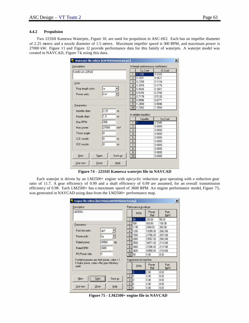
ASC Design – VT Team 2 Page 61
4.4.2 Propulsion
Two 225SII Kamewa Waterjets, Figure 10, are used for propulsion in ASC-HI2. Each has an impeller diameter of 2.25 meters and a nozzle diameter of 1.5 meters. Maximum impeller speed is 300 RPM, and maximum power is 27000 kW. Figure 11 and Figure 12 provide performance data for this family of waterjets. A waterjet model was created in NAVCAD, Figure 74, using this data.
Figure 74 - 225SII Kamewa waterjet file in NAVCAD
Each waterjet is driven by an LM2500+ engine with epicyclic reduction gear operating with a reduction gear ratio of 11.7. A gear efficiency of 0.99 and a shaft efficiency of 0.99 are assumed, for an overall transmission efficiency of 0.98. Each LM2500+ has a maximum speed of 3600 RPM. An engine performance model, Figure 75, was generated in NAVCAD using data from the LM2500+ performance map.
Figure 75 - LM2500+ engine file in NAVCAD
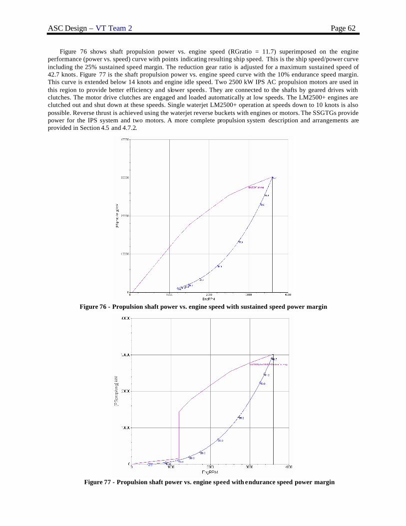
ASC Design – VT Team 2 Page 62
Figure 76 shows shaft propulsion power vs. engine speed (RGratio = 11.7) superimposed on the engine performance (power vs. speed) curve with points indicating resulting ship speed. This is the ship speed/power curve including the 25% sustained speed margin. The reduction gear ratio is adjusted for a maximum sustained speed of 42.7 knots. Figure 77 is the shaft propulsion power vs. engine speed curve with the 10% endurance speed margin. This curve is extended below 14 knots and engine idle speed. Two 2500 kW IPS AC propulsion motors are used in this region to provide better efficiency and slower speeds. They are connected to the shafts by geared drives with clutches. The motor drive clutches are engaged and loaded automatically at low speeds. The LM2500+ engines are clutched out and shut down at these speeds. Single waterjet LM2500+ operation at speeds down to 10 knots is also possible. Reverse thrust is achieved using the waterjet reverse buckets with engines or motors. The SSGTGs provide power for the IPS system and two motors. A more complete propulsion system description and arrangements are provided in Section 4.5 and 4.7.2.
Figure 76 - Propulsion shaft power vs. engine speed with sustained speed power margin
Figure 77 - Propulsion shaft power vs. engine speed with endurance speed power margin

ASC Design – VT Team 2 Page 63
Figure 78 and Figure 79 show propulsion efficiency and total power available versus engine speed. Figure 80 shows fuel consumption per engine with 10% endurance power margin versus ship speed.
Figure 78 - Propulsion Efficiency (PC) vs. Speed
Figure 79 - Total Engine Power vs. Engine Speed (2 engines)

ASC Design – VT Team 2 Page 64
Figure 80 - Fuel consumption vs. Ship Speed
4.4.3 Electric Load Analysis (ELA)
Electric power requirements for SWBS groups 100 through 700 equipment and machinery are summarized in the Electric Load Analysis Summary, Table 39. Load factors are used to estimate the electric power requirement for each component in each of five operating conditions, including Condition 1, loiter, cruise, in-port, anchor, and emergency. The SSGTGs are very lightly loaded in all conditions. 1500 kW SSDGs will be considered in subsequent design iterations.
Table 39 - Electric Load Analysis Summary SWBS Condition I (kW) Loiter (kW) Cruise (kW) In Port (kW) Anchor (kW) Emergency (kW)
100 0 0 0 17.1 11.5 0200 225.2 225.2 225.2 0 0 204.6300 71.6 71.6 71.6 34.8 34.8 50.3
430&475 101.4 101.4 101.4 11.3 17.3 13.2510 421.6 421.6 421.6 421.6 421.6 97.6520 32.6 32.6 32.6 32.6 32.6 32.6
530&550 77.0 77.0 77.0 77.0 77.0 23.5540 55.1 55.1 55.1 0 0 0560 47.3 47.3 47.3 0 0 47.3600 34.4 34.4 34.4 34.4 34.4 16.8700 164.5 164.5 164.5 164.5 164.5 164.5
1230.7 1230.7 1230.7 793.2 793.6 650.41489.1 1489.1 1489.1 959.8 960.3 787.0
235 0 2319.4 0 0 0 01489.1 3808.5 1489.1 959.8 960.3 787.0
826.8 826.7 826.7 436.3 436.5 496.3
Number Generator Rating (kW) Condition I Loiter Cruise In Port Anchor Emergency3 SSGTG 3000 2 2 1 1 1 1
24 Hour Ship Service Average
Max Functional LoadMFL w/ MarginsElectric Propulsion DriveTotal Load w/ Margins
Fuel HandlingShip ControlServicesPayload
MiscellaneousHVACSeawater SystemsMisc. Auxiliary
DescriptionDeckPropulsionElectric
4.4.4 Fuel Calculation
A fuel calculation is performed for endurance range and sprint range in accordance with DDS 200-1. The fuel calculations are shown in Figure 81. Results indicate an endurance range of 3881 nm and a sprint range of 1241 nm satisfying endurance range thresholds specified in the ORD.
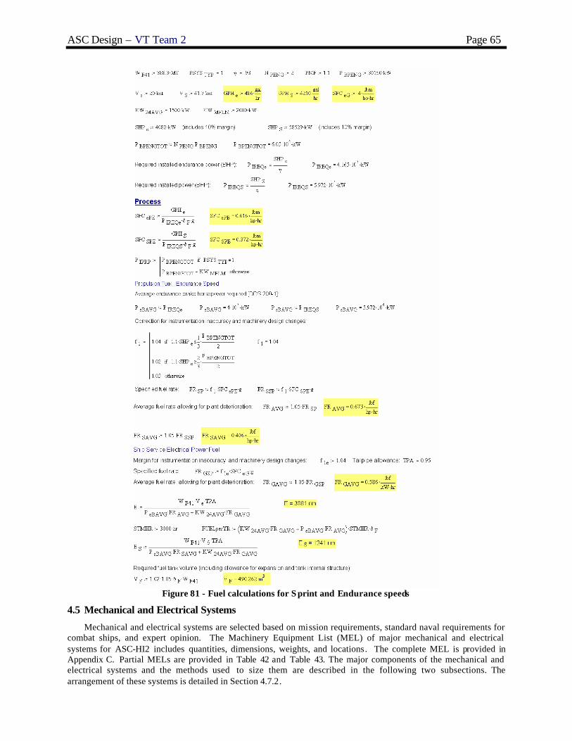
ASC Design – VT Team 2 Page 65
Figure 81 - Fuel calculations for S print and Endurance speeds
4.5 Mechanical and Electrical Systems
Mechanical and electrical systems are selected based on mission requirements, standard naval requirements for combat ships, and expert opinion. The Machinery Equipment List (MEL) of major mechanical and electrical systems for ASC-HI2 includes quantities, dimensions, weights, and locations. The complete MEL is provided in Appendix C. Partial MELs are provided in Table 42 and Table 43. The major components of the mechanical and electrical systems and the methods used to size them are described in the following two subsections. The arrangement of these systems is detailed in Section 4.7.2.

ASC Design – VT Team 2 Page 66
4.5.1 Integrated Power System (IPS)
Due to the US Navy’s commitment to all-electric ships, integrated power system options were considered for ASC and selected for ASC HI2 in concept development. Solid-state power electronics devices utilizing programmable microprocessor-based digital control, such as silicon controlled rectifiers, thyristors, and more recently, isolated gate bipolar transistors (IGBTs), make it possible to utilize fixed frequency alternating current generator sets (SSGTGs on ASC) supplying a common bus which feeds both propulsion and ship service loads.
Figure 82 shows the one-line diagram for ASC secondary propulsion and ship service power. Three Ship Service Gas Turbine Generators (SSGTGs) provide 460 volt, 60 Hz electric power to the primary switchboards. This power may be routed to ship service loads through Power Conversion Modules and the port and starboard zonal buses, or to the propulsion buses and power converters which control the speed of the ship when in IPS secondary propulsion mode by varying the AC frequency to the two AC propulsion motors. The power converters have 3 parallel elements. Each switchboard is connected to both motors for redundancy and survivability.
To support the IPS power specified in the ELA, the SSGTGs are rated at 3000 kW each. Propulsion motors are rated at 2500 kW each. There is one propulsion motor with drive gear and clutch per shaft. The generator sets each have a generator control panel for local control, and may be automatically or manually started both locally and remotely from the EOS. Automatic paralleling and load sharing capability are provided for each set.
Figure 82 - One-Line Electrical Diagram

ASC Design – VT Team 2 Page 67
4.5.2 Service and Auxiliary Systems
Tanks for lube oil, fuel oil, and waste oil are sized based on requirements from the Ship Synthesis model. Equipment capacity and size are based on similar ships. Most equipment is located either in the Main Machinery Rooms or the Auxiliary Machinery Room.
Fuel and lube oil purifiers are sized relative to the fuel and oil consumption of each engine. There are two fuel oil purifiers and two lube oil purifiers located in the purifier rooms between MMR1 and MMR2. They are located on the port and starboard sides of a longitudinal bulkhead. One set is for purifying the fuel and oil in MMR1 and the other for MMR2, but the systems may be cross-connected.
Two reverse osmosis distillers are used to produce potable water from seawater. They are located in the AMR. For ASC HI2, the volume of the potable water tank is 14 m3. This supports an allotment of 0.16 m3 of water per person per day for the 88 person crew. Two 76 m3 per day distillers are located in the AMR. This allows for refilling of the potable water tanks. Distillate pumps are used to pump water from the distillers to the potable water tanks. Potable water pumps are used to pressurize the potable water system from the tanks.
Four air conditioning plants and two refrigeration plants are required for ASC HI2. The air conditioning plants are sized based on crew size and arrangeable area. There are 4 air conditioning plants at 150 tons each. The refrigeration plants are sized at 10 tons per 200 crew, so two refrigeration plants at 4.3 tons each are used. JP-5 pumps and filters are located in the JP-5 pump rooms.
4.5.3 Ship Service Electrical Distribution
ASC HI2 has an integrated power system (IPS) supporting secondary propulsion and ship service power. Ship service power is distributed from any of the three main switchboards via a zonal bus, as shown in Figure 82. Power Conversion Modules (PCMs) are located in each zone to convert ship service power as required, provide circuit protection and automatic reconfiguration. They are able to convert AC to DC and DC to AC as required. Power from the main switchboards is supplied to the main switchboards by the three SSGTGs. Secondary propulsion power is also supplied from the 3 ship service switchboards. The ship is divided into 5 CPS and Electrical Distribution Zones. Electric power is taken from the zonal buses in each zone through the power conversion modules. If there is a vital system in a zone it draws power from both the port and starboard buses through a power conversion module and an ABT which is an automated switch to either bus in case of power loss of one of the zonal buses.
Zonal systems are also used for the ship’s firemain system and Collective Protection System. The firemain is located on the Damage Control Deck with fire pumps in each zone. CPS zones are separated by air locks with airlocks on all external accesses.
4.6 Manning
An important goal for ASC is to reduce manning significantly from current Navy standards by utilizing automation and unmanned systems . ASC-HI2 has a crew of 88. Accommodations are provided for a crew of 104 to support additional crew for mission packages. The use of unmanned craft and an automated bridge are significant factors in this reduction. ASC uses various watch standing technologies including GPS, automated route planning, electronic charting and navigation, collision avoidance, and electronic log keeping. Video teleconferencing also provides a large reduction in manning because it provides quick access to onshore experts, which reduces the number of ship experts required onboard. ASC’s original manning estimates were made using the ship synthesis model. These estimates were based on ship scaling factors for the size of the ship, number of propulsion systems, and ship displacement. These estimates were further refined by comparison to the manning of other naval ships. In concept development, the total manning is allocated by department and resized based on the ASC unique mission and by analogy with other ships. Engineering is the most manning intensive department on ASC. The manning estimates are based on an assumption of Watch Condition III (3 watch sections of 8 hours each), and are summarized in Table 40 and Figure 83.

ASC Design – VT Team 2 Page 68
Table 40 - Manning Summary ASC-HI2
Departments Division Officers CPO Enlisted Total Department
CO/XO 2 2 Department Heads 4 Executive/Admin Administration 1 1 2
Operations Communications 1 1 3 22 Navigation and Control 1 3 Electronic Repair 1 2
CIC, EW, Intelligence 1 1 6 Medical 1
Weapons Air 2 1 2 24 Boat and Vehicle 1 3 Deck 1 6 Ordnance/Gunnery 1 2 ASW/MCM 1 3
Engineering Main Propulsion 1 8 25 Electrical/IC 1 3 Auxiliaries 1 3 Repair/DC 1 6
Supply Stores 2 13 Material/Repair 1 2 Mess 1 6 Total Crew 10 17 61 88 Accommodations 14 18 72 104
CO
XO
Executive/Admin
Department
OperationsDepartment
WeaponsDepartment
EngineeringDepartment
SupplyDepartment
Communications Air
Navigation andShip Control
Deck Seamanship(FIRST)
Ordnance/Gunnery
Boat and VehicleMaintenance and
Seamanship
ASW and MCM
ElectronicRepair
Main Propulsion
Electrical and IC
Auxiliaries
Repair/DCCIC, EW,Intelligence
Stores
Mess
Material,Repair
Medical
Figure 83 – ASC Manning Organization

ASC Design – VT Team 2 Page 69
4.6.1 Executive/Administration Department
The Executive/Administration department maintains personnel records and manages the overall administration of all the departments. This department does not have a department head (they report to the XO), but has one CPO and one enlisted (yeoman and personnelman).
4.6.2 Operations Department
The Operations department is responsible for sensor and combat systems, radio operations, communications, watch standing, maintenance of electronic and communication equipment, and medical operations. This department is assigned 1 department head and 2 officers, one to head the Communications division and one to head the CIC, EW, and Intelligence division. The department is also assigned 5 CPOs, one for each division, and 14 enlisted.
This department is comprised of the following five divisions: Communications, Navigation and Control, Electronic Repair, CIC, EW, and Intelligence, and Medical. The Communications division is required to interpret the electronic output of the systems and relay any important information gathered. This division requires three enlisted working 8 hour days and therefore will require 3 enlisted as well as one officer and one CPO. The Navigation division is responsible for navigating and meteorology. Navigation watch also requires three enlisted working 8 hour days at each position. Therefore this department is assigned 3 enlisted as well as one CPO. The Electronic Repair division maintains electronics equipment. This division requires a minimum of 2 enlisted and one CPO for maintenance and expertise. The CIC, EW, and Intelligence div ision is responsible for electronic warfare and manning the bridge, as well as gathering and providing intelligence to the CO. This division requires 2 enlisted working 8 hour days. Therefore, this division requires 6 enlisted, one CPO, and one officer. Due to the small crew size the medical department requires few personnel, and is therefore assigned one CPO.
4.6.3 Weapons Department
The Weapons department is responsible for the assembly, loading, and transportation of shipboard weapons, weapons maintenance, and specialized weapons use. The weapons department is also required to organize, maintain, and oversee the supply of all weapons magazines. This department issues ammunition from the ship’s arsenal. There is one department head, 2 officers for the Air division (LAMPS pilots), 5 CPOs, one for each division, and 16 enlisted in this department.
This department includes the following five divisions: Air, Boat and Vehicle, Deck, Ordnance/Gunnery, and ASW/MCM. The Air division is responsible for manning the LAMPS, and for maintenance and support of the LAMPS and VTUAVs. This division is assigned 2 officers, one CPO, and 2 enlisted. Two of these personnel are assigned as pilots of the LAMPS. The Boat and Vehicle division is responsible for launching and recovering the RHIBs and Spartans and maintenance on both. This division requires one CPO and 3 enlisted. The deck division is responsible for line handling, anchoring, life boat maintenance, topside maintenance, and helmsmen. Line handling and anchoring occur only when the ship is in port. Most crew are assigned to maintenance work and transferred to line handling and anchoring as needed. There is one CPO and 6 enlisted crew assigned to the Air department. The Ordnance/Gunnery department is responsible for procuring, maintaining, and issuing weapons and ammunition as well as operation of the CIWS and CIGS. This division is assigned one CPO and 2 enlisted. The ASW/MCM division is responsible for launching, operating, and recovering the 2 RMS and the VANGUARD Mine Avoidance Sonar. This division is assigned one CPO and 3 enlisted.
4.6.4 Engineering Department
The Engineering department is responsible for operating and maintaining the two LM2500+ engines, their support systems, three DDA 501-K17 ship service gas turbine generators, all of their support systems, the electrical systems of the ship, weapons elevators, and most other major mechanical or electrical equipment on the ship. This department has one department head, 4 CPOs, one for each division, and 20 enlisted.
This department consists of the following four divisions: Main Propulsion, Electrical/IC, Auxiliary, and Repair/Damage Control. The Main Propulsion division is responsible for maintenance and repair of the main propulsion engines and their support systems. This division consists of one CPO and 8 enlisted. The Electrical/IC division is responsible for all of the ships electrical systems. This division includes one CPO and 3 enlisted. The Auxiliary division is in charge of major auxiliary equipment including LAMPS equipment, weapons elevators, motorized doors and hatches, pumps, and damage control equipment. This division is assigned one CPO and 3 enlisted. The Repair/Damage Control division is primarily responsible for repairing any major proble ms that may result from damage to the ship as well as controlling any damage as it occurs. This division requires one CPO and 6 enlisted. The reduction in manning for this division is enabled by the use of damage control robots.

ASC Design – VT Team 2 Page 70
4.6.5 Supply Department
The Supply department is responsible for ordering, receiving, organizing, and storing food, spare parts, equipment, and other material. They are also responsible for food preparation, including cooking, cleaning, beverages, and inventory. These personnel are in charge of the ships laundry, retail, tailoring, and dry cleaning. They man the ships store, barbershop, and postal service and are responsible for distributing pay. This department is assigned one department head, 2 CPOs, and 10 enlisted.
This department is divided into the following three divisions: Stores, Material/Repair, and Messing. The Stores division is responsible for maintaining the supplies onboard the ship. Due to the size of the crew, this division does not require high manning and therefore is only assigned 2 enlisted. The Material/Repair division is responsible for obtaining materials and supplies for repair of damaged equipment. This division is assigned one CPO and 2 enlisted. The Messing division is responsible for food preparation for the entire ship. Due to the use of automated mess, this division is only assigned one CPO and 6 enlisted.
4.7 Space and Arrangements
HECSALV and AutoCAD are used to generate and assess the subdivision and arrangements of ASC-HI2. HECSALV is used for primary subdivision, tank arrangements and loading. AutoCAD is used to construct 2-D drawings of the inboard and outboard profiles, deck and platform plans, detailed drawings of berthing, sanitary, and messing spaces , and a 3-D model of the ship. A profile of ASC-HI2 showing the internal arrangements is shown in Figure 84.
Figure 84 - Profile View Showing Arrangements
4.7.1 Volume
Initial space requirements and availability in the ship are determined in the ship synthesis model. Volume parameters output by the ship synthesis model are as follows: the machinery box height and volume, and volumes of the waste oil, lube oil, potable water, sewage, helicopter fuel, clean ballast, and propulsion fuel. These are shown in Table 41. Given the volumes and hull form, tanks are arranged in HECSALV. Lightship weight, load cases, and ballast locations are coordinated with the weight and stability analysis for proper placement. The remaining space in the ship is used primarily as arrangeable space. Arrangeable area estimates and requirements are refined in concept development arrangements and discussed in Sections 4.7.2 through 4.7.4.
Table 41 - Required, Available, Actual Space Variables from Ship Synthesis Model Variable Required Final Concept Design
Machinery Box Height 5 m 7.046 m Machinery Box Volume 1845 m3 1845 m3 Waste Oil 8.7 m3 10 m3 Lube Oil 20.8 m3 21 m3 Potable Water 13.6 m3 14 m3 Sewage 5.5 m3 8 m3 Helicopter Fuel (JP5) 133.7 m3 147 m3 Clean Ballast 119.9 m3 123 m3 Propulsion Fuel (DFM) 436 m3 455 m3
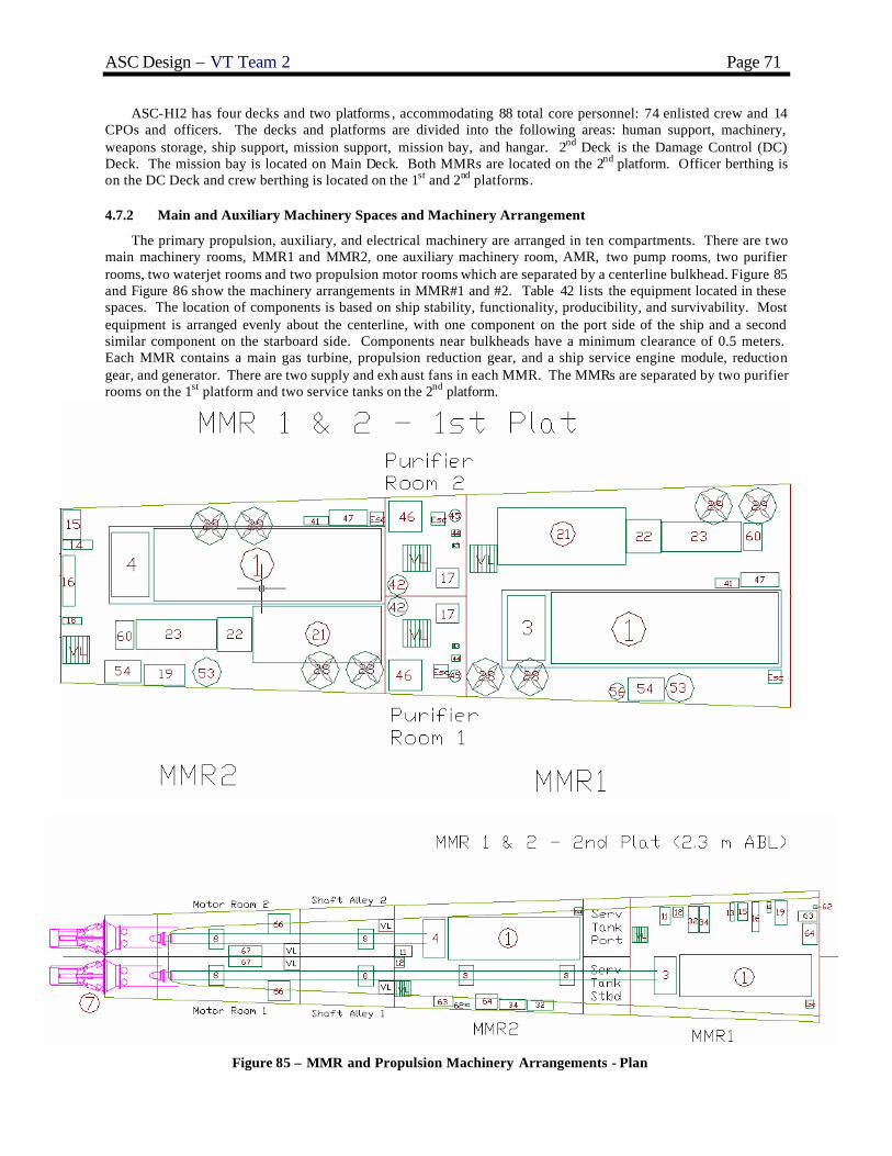
ASC Design – VT Team 2 Page 71
ASC-HI2 has four decks and two platforms , accommodating 88 total core personnel: 74 enlisted crew and 14 CPOs and officers. The decks and platforms are divided into the following areas: human support, machinery, weapons storage, ship support, mission support, mission bay, and hangar. 2nd Deck is the Damage Control (DC) Deck. The mission bay is located on Main Deck. Both MMRs are located on the 2nd platform. Officer berthing is on the DC Deck and crew berthing is located on the 1st and 2nd platforms.
4.7.2 Main and Auxiliary Machinery Spaces and Machinery Arrangement
The primary propulsion, auxiliary, and electrical machinery are arranged in ten compartments. There are two main machinery rooms, MMR1 and MMR2, one auxiliary machinery room, AMR, two pump rooms, two purifier rooms, two waterjet rooms and two propulsion motor rooms which are separated by a centerline bulkhead. Figure 85 and Figure 86 show the machinery arrangements in MMR#1 and #2. Table 42 lists the equipment located in these spaces. The location of components is based on ship stability, functionality, producibility, and survivability. Most equipment is arranged evenly about the centerline, with one component on the port side of the ship and a second similar component on the starboard side. Components near bulkheads have a minimum clearance of 0.5 meters. Each MMR contains a main gas turbine, propulsion reduction gear, and a ship service engine module, reduction gear, and generator. There are two supply and exh aust fans in each MMR. The MMRs are separated by two purifier rooms on the 1st platform and two service tanks on the 2nd platform.
Figure 85 – MMR and Propulsion Machinery Arrangements - Plan

ASC Design – VT Team 2 Page 72
Figure 86 - MMR and Propulsion Machinery Arrangements - Profile
Table 42 - Main Machinery Room Equipment
Item Equipment Nomenclature Capacity Rating1 Gas Turbine, Main 26100 kW @ 3600 RPM3 Gear, Propulsion Reduction (stbd)4 Gear, Propulsion Reduction (port)8 Bearing, Line Shaft 0.575 m line shaft10 Console, Main Control11 Strainer, Sea Water12 Pump, Main SW Circ 230 m3/hr @ 2 bar13 Pump, Stbd rd gear lube oil service 200 m3/hr @ 5 bar14 Pump, Pt rd gear lube oil service 154 m3/hr @ 5 bar15 Strainer, Rd gear lube oil 200 m3/hr 16 Cooler, Rd gear lube oil17 Purifier, Lube Oil 1.1 m3/hr 18 Pump, Lube Oil Transfer 4 m3/hr @ 5 bar19 Assembly, GT Lube Oil Storage and Conditioning21 SS Eng Enclosure Module22 SS Reduction Gear23 SS Generator28 MMR Supply Fan 94762 m3/hr29 MMR Exhaust Fan 91644 m3/hr32 Pump, Fire 454 m3/hr @ 9 bar34 Pump, Bilge 227 m3/hr @ 3.8 bar41 Pump, GT Fuel Booster 15.9 m3/hr42 Filter Separator, GT Fuel 30 m3/hr43 Heater, GT Fuel Service 10.4 m3/hr44 Heater, Fuel Service 7.0 m3/hr45 Pre-filter, GT Fuel Service 30 m3/hr46 Purifier, Fuel Oil 7.0 m3/hr47 Pump, Fuel Transfer 45.4 m3/hr @ 5.2 bar53 Receiver, Starting air 2.3 m354 Compressor, Starting air 80 m3/hr FADY @ 30 bar56 Receiver, Control Air 1 m360 GT Hydraulic Starting Unit 14.8 m3/hr @ 414 bar62 Oil Content Monitor 15 PPM63 Pump, Oily Waste Transfer 12.3 m3/hr @ 7.6 bar64 Separator, Oil/Water 2.7 m3/hr66 IPS Motors67 Frequency Converter

ASC Design – VT Team 2 Page 73
Figure 87 - AMR and Pumproom Arrangements
Figure 87 shows the general machinery arrangements in the auxiliary machinery room (AMR) and pump rooms . Table 43 lists the equipment located in these spaces . The upper level of the auxiliary machinery room houses four air conditioning plants and two refrigeration plants. The lower level houses two fresh water distillers. Just like the MMRs, the AMR contains a ship service generator engine module, reduction gear, and generator. It also contains fire and bilge/ballast pumps.
Table 43 - AMR and Pump Room Equipment
Item Equipment Nomenclature Capacity Rating21 SS Eng Enclosure Module22 SS Reduction Gear23 SS Generator25 Switchboard, Emergency26 Air Conditioning Plants 150 Ton27 Refrigeration Plants 4.3 Ton30 AMR Supply Fan 61164 m3/hr31 AMR Exhaust Fan 61164 m3/hr32 Pump, Fire 454 m3/hr @ 9 bar33 Pump, Fire/Ballast 455 m3/hr @ 9 bar35 Pump, Bilge/Ballast 227 m3/hr @ 3.8 bar36 Fresh Water Distiller 76 m3/day (3.2 m3/hr)37 Brominator 1.5 m3/hr38 Pump, Chilled Water AC 128 m3/hr @ 4.1 bar39 Pump, Potable Water 22.7 m3/hr @ 4.8 bar40 Brominator 5.7 m3/hr48 Pump, JP5 Transfer 11.5 m3/hr @ 4.1 bar49 Pump, JP5 Service 22.7 m3/hr @ 7.6 bar50 Pump, JP5 Stripping 5.7 m3/hr @ 3.4 bar51 Filter/Separator, JP5 Transfer 17 m3/hr52 Filter/Separator, JP5 Service 22.7 m3/hr55 Receiver, Ship Service Air 1.7 m
3
57 Compressor, Air, LP Ship Service 8.6 bar @ 194 SCFM58 Dryer, Air 250 SCFM60 GT Hydraulic Starting Unit 14.8 m
3/hr @ 414 bar
61 Sewage Collection Unit 28 m365 Sewage Plant 225 people

ASC Design – VT Team 2 Page 74
4.7.3 Internal Arrangements
Six space classifications are considered in the internal arrangements: hangar space, machinery rooms, weapons magazines, human support, ship support, and mission support. Area and volume estimates for these spaces were initially taken from the ship synthesis model and refined in the process of arranging the ship. Appendix E lists the area and volume summaries for ASC-HI2 by SWBS group.
Combat operations and vehicle support requires the largest area in the ship. The main deck and hangar deck are used primarily for LAMPS, VTUAV, and SPARTAN operations. These decks are located to most easily service, recover and launch these combat vehicles. The helo hangar is used to service, store, and prepare the LAMPS for missions. The helo hangar is connected directly to the weapons magazine by a weapons elevator. The moon pool is located on Main Deck and is used for all surface vehicle deployment and recovery as well for the Remote Minehunting System (RMS). It is located aft of amidships between the center hull and the port outer hull. The center and outer hulls provide protection of the moon pool, which allows for safe deployment and recovery of the surface vehicles and RMS even during hostile engagement.
Machinery rooms are located on the lowest deck of the ship, 2nd platform, and sized for the ships mechanical and electrical systems. Two main machinery rooms and one auxiliary machinery room contain the waterjet propulsion engines and ship service generators. Other mechanical and electrical systems including air conditioning, distillers, firemain, etc., are fit in the remaining space. Machinery rooms are separated for survivability, particularly SSGTGs and fire pumps required for firefighting. Damage Control (DC) Central and repair lockers are located on DC Deck just above MMR2. The intake and exhaust ducts for each machinery room exit the side of the ship just below the damage control deck. All exhausts are placed on the opposite side of the main hull from the moon pool. The intake and exhaust locations are chosen to minimize the area lost to ducting through the ship, and to minimize topside RCS and impact on topside mission operations
ASC-HI2 has one main weapons magazine located on the 2nd platform. The magazine stores the aircraft and surface vehicle weapons and ship weapons. There are two CIGS magazines located directly under the CIGS on main deck and damage control deck.
Ship support spaces are located throughout the ship. Each department requires its own support facilities; therefore support facilities are located close to the individual department location. Ship support looks after the day-to-day operations of the ship, such as administration, maintenance, stores handling, damage control, etc.
Mission Support areas are primarily located in or near the mission bay and helo hangar on main deck and hangar deck. These areas include the pilothouse and flight operations control. CIC is located on the 1st platform between the AMR and crew berthing. It is well embedded in the ship for survivability.
Tankage for ASC-HI2 is located primarily below the 2nd platform. This puts the weight associated with the ships fuel, oil, etc., as low as possible. Table 41 lists the required and actual tankage for ASC-HI2. Propulsion fuel tanks are located just forward of the MMRs allowing for easier transfer of fuel to the engines. Saltwater ballast tanks are placed in the extreme fore and aft of the ship. This requires less volume to correct trim conditions. Table 44 lists the individual tanks throughout the ship and their volumes.
The Main passageway is located along the centerline of the hull and runs longitudinally along the entire length of the DC (2nd) deck. This provides easy access into and out of compartments with sufficient width for DC equipment. Secondary passageways run transversely through the ship and are required only on main deck. Main passageways are 1.5 meters wide and secondary passageways are 1 meter wide. All main passageways have watertight doors located at the watertight bulkheads. Below the damage control deck there is no longitudinal access to compartments. Ladders provide vertical access through watertight hatches to the damage control deck and the main passageways. Figure 88 and 88 show the passageways on main deck and DC Deck.
A complete set of detailed arrangement drawings are included with this report.

ASC Design – VT Team 2 Page 75
Figure 88 - Damage Control (2nd) Deck
Figure 89 - Main Deck
Table 44 - Individual Tanks and Volumes
Tank Capacity (m3) Tank Capacity (m3) Fuel (JP5) ----- Lube Oil -----
JP5 Port 75 Lube Oil Port 11 JP5 Stbd 75 Lube Oil Stbd 11
Fuel (DFM) ----- Waste Oil ----- DFM Fwd Stbd 57 Waste Oil 10 DFM Fwd Port 57 Fresh Water -----
DFM Port Sidehull 1 10 Potable Water Port 7 DFM Port Sidehull 2 42 Potable Water Stbd 7 DFM Port Sidehull 3 48 Salt Water Ballast ----- DFM Port Sidehull 4 27 SWB Aft1 Port 25 DFM Stbd Sidehull 1 10 SWB Aft2 Port 5 DFM Stbd Sidehull 2 42 SWB Aft3 Port 3 DFM Stbd Sidehull 3 48 SWB Aft1 Stbd 25 DFM Stbd Sidehull 4 27 SWB Aft2 Stbd 5
AMR Service Port 5 SWB Aft3 Stbd 3 AMR Service Stbd 5 SWB Fwd Port 29
MMR1 Service Stbd 19 SWB Fwd Stbd 29 MMR1 Service Port 19 Sewage ----- MMR2 Service Port 24 Sewage Port 4 MMR2 Service Stbd 24 Sewage Stbd 4

ASC Design – VT Team 2 Page 76
The ship is divided into 5 Collective Protection System (CPS) and electrical distribution zones as shown in Figure 90. CPS Zone 1 contains the Auxiliary Machinery Room (AMR). The CIC and Magazine, as well as some officer berthing, is located in CPS Zone 2. Most of the crew berthing and the rest of the officer berthing are included in CPS Zone 3. CPS Zone 4 contains Main Machinery Room 1 (MMR1) and crew mess. The 2nd Main Machinery Room (MMR2), the rest of the crew berthing, and the propulsion motors are located in CPS Zone 5. CPS zones are separated by airlocks with airlocks on all external accesses. Each CPS Zone has its own Fan Room that supplies ventilation. Zonal systems are also used for ship’s fire system. Fire mains are located on the Damage Control Deck and there are fire pumps in each zone.
Figure 90 - CPS Zones
4.7.4 Living Arrangements
Living area requirements were initially estimated based on crew size using the ship synthesis model and refined with the manning estimate. The model estimates areas for enlisted living, officer living, mess areas, and human support facilities. Living areas are located around midships and placed in close proximity to messing spaces and other human support spaces to simplify the flow of day-to-day traffic. Crew berthing spaces are located forward of midships on the 1st and 2nd platforms and officer berthing is located above them on the damage control deck. This is out of the way of traffic with spaces sufficiently separate for survivability. The officer berthing located on DC deck is shown in Figure 88. The crew berthing located on 1st and 2nd platform is shown in Figure 91.
The total crew size is 88 with accommodations for 104. Living arrangements for officer and enlisted berthing is shown in Figure 92. Table 45 lists the accommodation space for the crew. The CO and XO have their own spaces of 15 m2 and 10 m2, respectively. The department heads also have their own living spaces that are 8 m2 . There are accommodations for 8 other officers, 2 officers per space, with an area of 8 m2 for each of the 4 spaces. There are accommodations for 18 CPO in 6 spaces, 3 in each space, with 15 m2 allocated for each space. There are accommodations for enlisted crew of 72. There are 6 spaces allocated, 12 enlisted in each space. Each space has an area of 15 m2. There are 2 sanitary spaces for the 4 department heads and the possible 8 officers. Each of these spaces is 30 m2. The 18 CPOs have 3 sanitary spaces, each space is 25 m2. There are 6 sanitary spaces for the possible 72 enlisted crew with each space having an area of 20 m2. The crew and officer mess are both on DC Deck and shown in Figure 92. Both mess areas make use of an automated messing system.
Table 45 - Accommodation Space
ItemAccomodation
QuantityPer
SpaceNumber of
SpacesArea Each
(m2)Total Area
(m2)CO 1 1 1 15 15XO 1 1 1 10 10Department Head 4 1 4 8 32Other Officer 8 2 4 8 32CPO 18 6 3 15 45Enlisted 72 12 6 15 90Officer Sanitary 12 6 2 30 60CPO Sanitary 18 6 3 25 75Enlisted Sanitary 72 12 6 20 120Total 30 479

ASC Design – VT Team 2 Page 77
Figure 91 - 1st and 2nd Platform Arrangements
Figure 92 - Officer and Crew Berthing Arrangements

ASC Design – VT Team 2 Page 78
All berthing and sanitary spaces are arranged as producible modules that may be prefabricated and installed on the ship as units with standard hook-ups for piping, ventilation and electrical.
4.7.5 External Arrangements
The most important criteria for external arrangements are Radar Cross Section, aircraft operations and combat systems effectiveness. All sides of the hull, above the waterline, are angled in at ten degrees from the vertical. The ten-degree angle is also included in the design of the AEM located on top of the helo hangar.
The AEM is positioned at the forward end of the hangar. This location was selected to reduce any type of interference for the LAMPS and VTUAV when landing. The AEM is angled at 10 degrees from top to bottom.
There are two CIWS located on top of the helo hangar at the very forward and aft ends. These locations allow for the most effective angle for defense when targeting incoming aircraft or missiles. The 30mm CIGS is located near the bow for this same reason. Figure 93 is an external profile view showing the coverage zones for the 2 CIWS and CIGS.
Anchor handling and mooring are located at the forward end of the Main Deck. Anchor stowage is located just aft of the forward saltwater ballast tank between the baseline and 1st platform. Life boats are stored in the mission bay along with the 7m RHIB and are deployed through the moon pool.
Figure 93 - Combat Systems Coverage Zones
4.8 Weights and Loading
4.8.1 Weights
Ship weights are grouped by SWBS. Weights were obtained from manufacturer information, when possible, and from the ship synthesis model and ASSET parametrics. Weight values calculated by the ship synthesis model are used when no other values are available. VCGs and LCGs for weights are estimated from machinery and ship arrangements. These centers are used to find moments and the lightship COG. A summary of lightship weights and centers of gravity by SWBS group is listed in Table 46. The entire weights spreadsheet is listed in Appendix D.
Table 46 - Lightship Weight Summary SWBS Group Weight (MT) VCG (m-Abv BL) LCG (m-Aft FP)
100 1180.14 5.31 62.76 200 345.97 4.35 105.04 300 102.03 5.53 56.51 400 118.77 8.48 63.00 500 197.96 6.40 56.25 600 131.99 5.94 58.70 700 11.28 10.5 63.00
Margin 104.41 5.78 71.87 Total (LS) 2192.53 5.78 71.87

ASC Design – VT Team 2 Page 79
4.8.2 Loading Conditions
Two loading conditions are considered for ASC: Full Load and Minimum Operating (Minop) as defined in DDS 079-1. The centers of gravity for the two loading conditions are calculated using the lightship weights and centers and loads weights and centers. Weights for the Full Load condition are estimated with all fuel oil and potable water tanks filled to 98% and full provisions, general stores, and weapons. The Minimum Operating condition assumes that all fuel, stores, and weapons are at 33% of their full load capacity, and that potable water tanks are 66% full. Compensated fuel/ballast tanks are used except for service tanks. A summary of the weights for the Full Load condition is provided in Table 47. A summary for the Minimum Operating condition is provided in Table 48.
4.9 Hydrostatics and Stability
To assess hydrostatics, intact stability, and damage stability of ASC-HI2, ship offsets are imported into HECSALV. Hydrostatics are calculated using a range of drafts. From this information, the curves of form, coefficients of form and cross curves are calculated. Using the data obtained from these calculations, intact stability is calculated in the two loading conditions. The ballast tanks are filled only as required for correct trim and heel. With intact load conditions defined and balanced, intact stability and damage stability are examined.
Table 47 - Weight Summary: Full Load Condition Item Weight (MT) VCG (m-BL) LCG (m-FP)
Lightship w/ Margin 2193 5.78 71.87 Ships Force 10.5 7.35 63.00
Total Weapons Loads 234.2 8.855 63.00 Aircraft 13.82 15.0 49.00
Provisions 5.2 5.25 63.00 General Stores 1.94 5.95 63.00
Diesel Fuel Marine 372 2.862 69.94 JP-5 116 1.353 59.871
Lubricating Oil 19 1.779 87.667 SW Ballast 0 0 0 Fresh Water 14 1.348 30.55
Total 2981 5.48 70.18
Table 48 - Weight Summary: Minop Condition Item Weight (MT) VCG (m-BL) LCG (m-FP)
Lightship 2193 5.78 71.87 Ships Force 10.5 7.35 63.00
Total Weapons Loads 234.2 8.855 63.00 Aircraft 13.82 15.0 49.00
Provisions 5.2 5.25 63.00 General Stores 1.94 5.95 63.00
Diesel Fuel Marine 123 2.06 80.825 JP-5 40 0.718 59.729
Lubricating Oil 7 1.425 87.583 Compensated Fuel-Ballast 304 3.107 64.774
SW Ballast 0 0 0 Fresh Water 9 1.035 30.55
Total 2942 5.55 70.39

ASC Design – VT Team 2 Page 80
Table 49 - Minop Trim and Stability Summary Weight VCG LCG TCG FSMom Item MT m m-MS m-CL m-MT Light Ship 2193 5.484 8.000F 0 --- Constant 234 8.855 8.000F 0 0 Lube Oil 7 1.425 24.583A 0 8 Fresh Water 9 1.035 32.450F 0 9 SW Ballast 0 --- --- --- --- Fuel (JP5) 40 0.718 3.271F 0 50 Comp. Fuel/Ballast 304 3.107 1.774A 0 --- Fuel (DFM) 123 2.06 17.825A 0 --- Waste Oil 9 1.732 21.613A 0 10 Sewage 10 1.234 9.5000F 0 1
Displacement 2928 5.265 5.776F 0 170 Stability Calculation Trim Calculation KMt 9.588 m LCF Draft 4.261 m VCG 5.265 m LCB (even keel) 5.949F m-MS GMt (Solid) 4.322 m LCF Draft 0.787A m-MS FSc 0.058 m MT1cm 77 m-MT/cm GMt (Corrected) 4.264 m Trim 0.066 m-A List 0 deg Specific Gravity 1.025 Hull calcs from tables Tank calcs from tables Drafts Draft at A.P. 4.293 m Draft at M.S. 4.26 m Draft at F.P. 4.227 m Draft at Aft Marks 4.293 m Draft at Mid Marks 4.26 m Draft at Fwd Marks 4.227 m
4.9.1 Intact Stability
In each condition, trim, stability and righting arm data are calculated. All conditions are assessed using DDS 079-1 stability standards for beam winds with rolling. For satisfactory intact stability two criteria must be met: (1) the heeling arm at the intersection of the righting arm and heeling arm curves must not be greater than six-tenths of the maximum righting arm; (2) the area under the righting arm curve and above the heeling arm curve (A1) must not be less than 1.4 times the area under the heeling arm curve and above the righting arm curve (A2).

ASC Design – VT Team 2 Page 81
Table 50 - Full Load Trim and Stability Summary Weight VCG LCG TCG FSMom Item MT m m-MS m-CL m-MT Light Ship 2193 5.484 8.000F 0 --- Constant 234 8.855 8.000F 0 0 Lube Oil 19 1.779 24.667A 0 9 Fresh Water 14 1.348 32.450F 0 6 SW Ballast 0 --- --- --- --- Fuel (JP5) 116 1.353 3.129F 0 70 Comp. Fuel/Ballast 0 0 0 0 0 Fuel (DFM) 372 2.862 6.940A 0 86 Waste Oil 0 --- --- --- --- Sewage 0 --- --- --- ---
Displacement 2947 5.216 5.827F 0 170 Stability Calculation Trim Calculation KMt 9.558 m LCF Draft 4.279 m VCG 5.216 m LCB (even keel) 5.908F m-MS GMt (Solid) 4.342 m LCF 0.793A m-MS FSc 0.058 m MT1cm 77 m-MT/cm GMt (Corrected) 4.284 m Trim 0.031 m-A List 0 deg Specific Gravity 1.025 Hull calcs from tables Tank calcs from tables Drafts Strength Calculations Draft at A.P. 4.294 m Bending Moment 158552 kN-m Draft at M.S. 4.278 m Draft at F.P. 4.263 m Draft at Aft Marks 4.294 m Draft at Mid Marks 4.278 m Draft at Fwd Marks 4.263 m
Figure 94 - Righting Arm (GZ) and Heeling Arm Curve for Minop Condition

ASC Design – VT Team 2 Page 82
Table 51 - Righting Arm (GZ) and Heeling Arm Data for Minop Condition Beam Wind with Rolling Stability Evaluation (per US Navy DDS079-1)
Displacement 2914 MT Angle at Maximum GZ 60 deg GMt (corrected) 4.264 m Wind Heeling Arm Lw 0.492 m Mean Draft 4.278 m Angle at Intercept 60.0 deg Projected Sail Area 1165 m2 Wind Heel Angle 7.3 deg Vertical Arm 9.488 m ABL Maximum GZ 3.949 m Wind Pressure Factor 0.0035 Righting Area A1 1.43 m-rad Wind Pressure 0.02 bar Capsizing Area A2 0.34 m-rad Wind Velocity 100 knts Heeling Arm at 0 deg 0.5 Roll Back Angle 25.0 deg
Figure 95 - Righting Arm (GZ) and Heeling Arm Curve for Full Load Condition
Table 52 - Righting Arm (GZ) and Heeling Arm Data for Full Load Condition Beam Wind with Rolling Stability Evaluation (per US Navy DDS079-1)
Displacement 2914 MT Angle at Maximum GZ 60 deg GMt (corrected) 4.264 m Wind Heeling Arm Lw 0.488 m Mean Draft 4.26 m Angle at Intercept 60.0 deg Projected Sail Area 1160 m2 Wind Heel Angle 7.2 deg Vertical Arm 9.48 m ABL Maximum GZ 3.975 m Wind Pressure Factor 0.0035 Righting Area A1 1.45 m-rad Wind Pressure 0.02 bar Capsizing Area A2 0.34 m-rad Wind Velocity 100 knts Heeling Arm at 0 deg 0.496 m Roll Back Angle 25.0 deg
ASC-HI2 intact stability is satisfactory for both minimum operating and full load conditions.
4.9.2 Damage Stability
In addition to locating transverse bulkheads to satisfy floodable length requirements, the two load cases, Minimum Operation (Minop) and Full Load, are checked for damage stability using a 15% and 50% LWL damage length in accordance with DDS 079-01 for large multi-hulls . The 15% length is equal to an 18.9 meter damage length which is systematically applied along the length of the ship starting from the bow and moving aft. Worst case penetration to the centerline is used. The 50% damage case was applied along the outrigger section with damage only to the outrigger hulls and not the center hull. 72 damage cases were assessed for each loading condition. In all cases, the flooded angle of heel must be less than 15 degrees, the margin line must not be submerged, and remaining dynamic stability must be adequate (A1 > 1.4 A2).
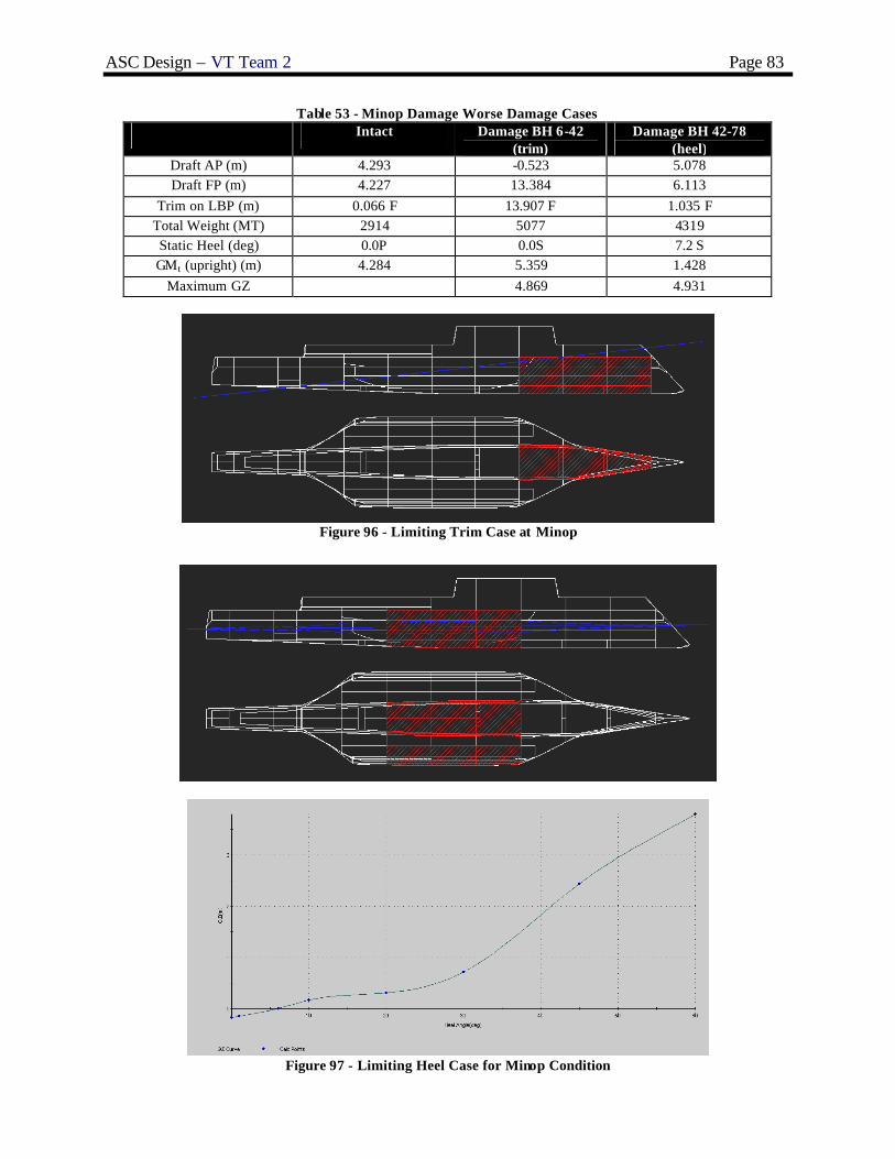
ASC Design – VT Team 2 Page 83
Table 53 - Minop Damage Worse Damage Cases Intact Damage BH 6-42
(trim) Damage BH 42-78
(heel) Draft AP (m) 4.293 -0.523 5.078 Draft FP (m) 4.227 13.384 6.113
Trim on LBP (m) 0.066 F 13.907 F 1.035 F Total Weight (MT) 2914 5077 4319 Static Heel (deg) 0.0P 0.0S 7.2 S GMt (upright) (m) 4.284 5.359 1.428
Maximum GZ 4.869 4.931
Figure 96 - Limiting Trim Case at Minop
Figure 97 - Limiting Heel Case for Minop Condition

ASC Design – VT Team 2 Page 84
Table 54 - Full Load Damage Results Intact Damage BH 6-42
(trim limit) Damage BH 42-78
(heel limit)
Draft AP (m) 4.294 -0.477 5.103 Draft FP (m) 4.263 13.434 6.180
Trim on LBP (m) 0.031A 13.911 F 1.077 A Total Weight (MT) 2953 5117 4366 Static Heel (deg) 0.0P 0.0S 8.0S GMt (upright) (m) 4.281 5.410 1.457
Maximum GZ 4.992 5.057 Maximum GZ Angle
(deg) 84S 86S
GZ Pos. Range (deg) 0 - 89 8 - 89
Figure 98 - Limiting Trim Case for Full Load Condition
Figure 99 - Limiting Heel Case for Full Load

ASC Design – VT Team 2 Page 85
The limiting trim case in the Minop condition is for flooding between bulkheads at Frames 6 and 42. The limiting heel case is for flooding between bulkheads at Frames 42 and 78. Tabular results are listed in Table 53. Figure 96 shows the trim case results with the damaged compartments in red. Figure 97 shows the results in the limiting heel case with righting arm curve, flooding Frames 42 to 78. ASC damaged stability is satisfactory in the Minop condition, although the trim case is severe.
The limiting case for trim in the Full Load condition is flooding between bulkheads at Frames 6 and 42. The limiting heel case is for flooding between bulkheads at Frames 42 and 78. Tabular results are listed in Table 54. Figure 98 shows the trim results with the damaged compartments in red. Figure 99 shows the results for the limiting heel case. ASC damage stability is satisfactory in the Full Load condition, although the worse trim case is again severe.
4.10 Seakeeping
A seakeeping analysis in the full load condition was performed using SWAN2. A strip theory or extended strip theory code is not adequate for the multi-hull application. The hull was modeled using offsets from FASTSHIP. Ship responses were calculated for regular waves in Sea States 3, 4, 5, 6, 7, and 8 (significant wave heights of 0.88, 1.88, 3.25, 5, 7.5, and 11.5 meters) for forward speeds of 5, 10, 20, 30, and 40 knots and at four or more headings. Ship accelerations were analyzed at 2 locations and angular motions were analyzed at the center of gravity. These locations are described in Table 55 below. SWAN2 created output files of general ship motion RAOs, and accelerations at the helo pad and bridge. The SWAN2 TECPLOT package was used to create Speed-Polar plots showing the operating envelopes of the ship for Required Operational Capabilities (ROCs) using US Navy Motion Limit Criteria by subsystem. The plots show the ship response for various headings and forward speeds. The bold red line indicates the system limit. Significant amplitude criteria are listed in Table 56.
Table 55 - Sea Keeping Analysis Locations
Application X location
from Midships, m
Y location from CL,
m
Z location from DWL,
m Vertical Launch and Recovery
-11 0 9
VERTREP -11 0 9
Helo Launch and Recovery -11 0 9
Bridge Personnel 32 0 11
Table 56 - Limiting Motion Criteria (Significant Amplitude) and Results
Application Roll Pitch Yaw Longitudinal Acceleration
Transverse Acceleration
Vertical Acceleration
ORD Threshold SeaState
Sea State Achieved
Bow Active Sonar
15° 5° - - - - 5 6,7 restricted 5 unrestricted
Vertical Launch and Recovery
17.5° 3° 1.5° 0.3g 0.7g 0.6g 4 6,7 restricted 5 unrestricted
VERTREP 4° - - - - - 4 7 restricted
6 unrestricted Helo Launch and Recovery
5° 3° - - - - 4 7 restricted
6 unrestricted
Bridge Personnel 8° 3° - 0.2g 0.2g 0.4g 7
7 restricted 6 unrestricted

ASC Design – VT Team 2 Page 86
The MCM mission is performed using a Bow Passive/Active Sonar. Bow Active Sonar maximum motion limits are 15 degrees roll and 5 degrees pitch. The Bow Active Sonar operating envelope is shown in Figure 100. Restricted operation is possible in Sea States 6 and 7. The acceptable operating range in Sea State 7 requires a heading of 040-130 or 220-340. Unrestricted operation is possible in Sea State 5.
Figure 100 - MCM mission (Bow Active Sonar) Speed-Polar Plot for Pitch in Sea State 7
Figure 101 - VTUAV Vertical Launch and Recovery Speed-Polar Plot for Pitch in Sea State 7

ASC Design – VT Team 2 Page 87
Figure 102 - VERTREP Speed-Polar Plot for Roll in Sea State 7
Figure 103 - Helo Launch and Recovery Speed-Polar Plot for Roll in Sea State 7

ASC Design – VT Team 2 Page 88
Figure 104 - Bridge Personnel Speed-Polar Plot for Vertical Acceleration in Sea State 7
VTUAV vertical launch and recovery maximum criteria are 17.5 degrees roll, 3 degrees pitch, and 1.5 degrees yaw. Longitudinal acceleration must be less than 0.3g, transverse acceleration less than 0.7g, and vertical acceleration less than 0.6g. VTUAV operations are limited by roll and pitch. Restricted operation is possible in Sea States 6 and 7. The Speed-polar plot of pitch in Sea State 7 is shown in Figure 101. The acceptable operating range in Sea State 7 requires a heading of 090-110 or 250-270. Unrestricted operation is possible in Sea State 5.
The criterion for Vertical Underway Replenishment is a maximum roll of 4 degrees. ASC is fully operational in Sea State 6 and limited in Sea State 7. The speed-polar plot for roll for Sea State 7 is shown in Figure 102. A heading of 030-330 (following seas) or 150-210 (head seas) is required to be within the criteria in Sea State 7.
ASW and ASUW missions are performed using LAMPS. The performance criteria for helo flight operations are 5 degrees roll and 3 degrees pitch. The seakeeping analysis indicates that helicopter flight operations are possible in all conditions in Sea State 6. The limiting factor for Sea State 7 is inability to meet roll and pitch criteria at the same time. Figure 103 is a Speed-polar plot showing the helo operating envelope for Sea State 7. The acceptable operating range from the aft landing spot for roll in Sea State 4 requires a heading of 150-210 (head seas) or 030-330 (following seas).
Seakeeping analysis at the location of the moon pool, for surface vehicle launch and recovery, is not calculated. The moon pool is located on Main Deck just below the helo pad where the VTUAVs and Helo are deployed and recovered. These aircraft have full capabilities for launch and recovery in Sea State 6. It is expected that the surface vehicles should have full launch and recovery capabilities in Sea State 4 or 5. This meets or exceeds the goal of Sea State 4 for surface vehicle launch and recovery. This must be demonstrated in the next design iteration. Sloshing and wave entry into the moon pool should also be investigated.
The performance degradation criteria for personnel are 8 degrees roll and 3 degrees pitch. Crew on the bridge must only be subjected to 0.2g lateral acceleration and 0.4g vertical acceleration. Figure 104 is a Speed Polar plot showing the operating envelope for personnel in Sea State 7. The limiting criterion in Sea State 7 is roll. The acceptable operating range requires a heading of 030-330 (following seas) or 150-210 (head seas).
ASC-HI2 satisfies bridge personnel requirements on restricted headings and exceeds requirements for VTUAV, Helo Launch and Recovery, VERTREP, and MCM active sonar applications.

ASC Design – VT Team 2 Page 89
4.11 Cost and Risk Analysis
4.11.1 Cost and Producibility
Cost calculations for ASC HI2 were based primarily on group weights using a proprietary NSWC cost spreadsheet. Concept Development changes resulted in a somewhat lower cost than originally estimated. A comparison of the costs is shown in Table 57. Acquisition cost satisfies the threshold value specified in the ORD.
Table 57 - Cost Comparison ENGINEERING INPUT
Concept Baseline
Final Concept Baseline
Hull Structure Material (select one)Steel 0 0Aluminum 1 1Composite 0 0
Deckhouse Material (select one)Steel 0 0Aluminum 1 0Composite 0 1
HullForm (select one)Monohull 0 0Catamaran 0 0Trimaran 1 1
Plant Type (select one)Gas Turbine 1 1Diesel 0 0Diesel Electric 0 0CODOG 0 0CODAG 0 0
Plant Power (select one)Power Rating (in SHP) 69,733 69,733
Main Propulsion Type (select one)Fixed Pitch Propeller 0 0Controllable Reversable Propeller 0 0Waterjet 1 1
Weights (provide in metric tons)100 (less deckhouse) 1163 1163150 (deckhouse) 18 18200 (less propeller) 207 237245 (propeller) 139 139300 102 102400 119 119500 198 198600 132 132700 11 11Margin 104 104
Lightship 2193 2222Full Load Displacement 2825 2825Operating and Support
Complement 87 87Steaming Hrs Underway / Yr 3000 3000Fuel Usage (BBL / Yr) 1052.81 1052.81Service Life (Yrs) 30 30
Cost ElementConcept Baseline
Final Concept Baseline
Shipbuilder $264 $275Government Furnished Equipment (a) $195 $203Other Costs $33 $11Operating and Support $391 $387
Personnel (Direct & Indirect) $109 $109Unit Level Consumption (Fuel, Supplies, Stores, etc) $60 $59Maintenance & Support $223 $220
Life Cycle Cost (less non-recurring) $882 $877 LCC Threshold $930M
Average Acquisition Cost $492M $489M Average Acquisition Cost Threshold $510M

ASC Design – VT Team 2 Page 90
ASC-HI2 is a producible design. A chine at the waterline transitions the curved wetted surfaces to a low-curvature freeboard. The entire hull above the waterline consists of single curvature or flat plating as does the transom. The cost of outfitting and installation is reduced by generous deck heights and the use of zonal distribution systems for electric power, firemain and ventilation. The variety of structural materials (plate and shapes) was kept to a minimum.
4.11.2 Risk Analysis
Based on the ASC OMOR, ASC-HI2 is a relatively high risk ship. This risk is due to the unproven cutting edge technology and concepts integrated into the design. The trimaran hullform, Wave Piercing Tumble Home (WPTH) hull form, Integrated Power System, unmanned aircraft and surface vehicles, automated systems, and aluminum structure are all high risk alternatives as described in Table 28. Additional technology demonstrations and tests are required to reduce this risk. An integrated test using the lead ASC-HI2 alternative would assess all high risk technologies simultaneously and could be considered as a lead (test) ship. This is a revolutionary approach.

ASC Design – VT Team 2 Page 91
5 Conclusions and Future Work
5.1 Assessment
ASC HI2 meets and exceeds the requirements specified in the ORD as shown in Table 58.
Table 58 - Compliance with Operational Requirements
Technical Performance Measure ORD TPM (Threshold)
Original Goal
Concept BL Final Concept BL
Number of VTUAVs 3 3 3 3
Number of SPARTANs 2 3 2 2
Number of LAMPS 1 2 1 1
Number of RMSs 2 4 2 2
Total mission payload weight (core, modules, fuel) (MT)
360 360 363 360
Endurance range (nm) 3600 4500 3503 3881
Sprint range (nm) 1000 1500 1196 1241
Stores duration (days) 24 24 24 24
CBR Partial Full Partial Partial
Sustained (Sprint) Speed Vs (knots) 40 50 38.9 42.7
Crew size 90 50 87 88
Maximum Draft (m) 4.4 3 4.21 4.368
Vulnerability (Hull Material) Aluminum Steel Aluminum Aluminum
Seakeeping capabilities (sea state)
- launch and recover aircraft SS4 SS5 --- SS5
- launch and recover watercraft SS3 SS4 --- SS5
- full capability of all systems SS5 SS6 --- SS6
- survive SS8 --- --- SS8
Follow-ship Acquisition cost ($M) 500 400 492 489
Life cycle cost ($M 2003) 900 800 882 877
Overall Measure of Effectiveness (OMOE) 0.584 1.0 0.584 0.693
Maximum level of risk (OMOR) 0.691 0.0 0.691 0.691
ASC incorporates an effective combination of proven technology and new cutting edge technology. It integrates the use of non-traditional modular mission packages designed for off-board unmanned operations in littoral regions. A stealthy, low radar cross section design is effectively incorporated in the hull form to satisfy the requirement for passive defense. The advanced enclosed mast maintains ASC HI2’s low radar cross section while protecting the ship’s electronic sensors. The two gas turbines satisfy the threshold value for sustained speed, while the integrated power system provides the ability to efficiently operate the waterjets at speeds below 14 knots. Manning is significantly reduced compared to other naval vessels through automation while maintaining a high integrity of operations. ASC exceeds Navy damage stability requirements.
5.2 Future Work
• Consider recovering power with IPS during use of LM2500+’s above speeds of 14 knots. • Consider details of LM2500+’s intake and exhaust. • Consider using diesel generators (SSDGs) or smaller SSGTGs . • Further reduce scantlings to optimize adequacy parameters and reduce weight. • Consider use of composite materials for the hangar and pilot house. • Consider the details of launching and retrieving operations with the moon pool. • Analyze structural and system vulnerability. • Assess reliability, maintainability and availability (RMA). • Consider corrosion prevention techniques for aluminum hulls. • Model flooded compartments in MAESTRO for each major damage case to assess damaged structural
integrity.

ASC Design – VT Team 2 Page 92
5.3 Conclusion
The ASC requirement is based on the LCS Flight 0 Preliminary Design Interim Requirements Document and ASC Acquisition Decision Memorandum (ADM ). ASC will operate in littoral areas, close-in, depend on stealth, with high endurance and low manning. It is required to support UCSVs, VTUAVs and LAMPS, providing for takeoff and landing, fueling, maintenance, weapons load-out, planning and control. The VTUAVs will provide surface, subsurface, shore, and deep inland intelligence, surveillance, reconnaissance (ISR) and electronic warfare. LAMPS will provide Anti-Submarine Warfare (ASW) and Anti-Surface Ship Warfare (ASUW) defense. The UCSVs can engage surface threats with anti-surface armaments, conduct SAR operations, support and conduct intelligence collection, and conduct surveillance and reconnaissance.
Concept Exploration trade-off studies and design space exploration were accomplished using a Multi-Objective Genetic Optimization (MOGO) after significant technology research and definition. Objective attributes for this optimization were life-cycle cost, risk (technology, cost, schedule and performance) and military effectiveness. The product of this optimization is a series of cost-risk-effectiveness frontiers which are used to select the ASC HI2 Baseline Concept Design and define Operational Requirements (ORD1) based on the customer’s preference for cost, risk and effectiveness.
ASC HI2 is the highest-end alternative on the life-cycle cost frontier. This design was chosen to provide a challenging design project using higher risk technology. ASC HI2 characteristics are listed below. ASC HI2 has a wave-piercing tumblehome (WPTH) hullform to reduce radar cross-section, and a unique moon pool for launching and recovering UCSVs and mine hunting systems (RMS). It uses significant automation technology including an automated mess, an Integrated Survivability Management System (ISMS), and watch standing technologies that include GPS, automated route planning, electronic charting and navigation (ECDIS), collision avoidance, and electronic log keeping. Concept Development included hull form development and analysis for intact and damage stability, structural finite element analysis, IPS system development and arrangement, general arrangements, combat system selection, seakeeping analysis, cost and producibility analysis and risk analysis. The final concept design satisfies critical operational requirements within cost and risk constraints with additional work required to improve structural and system vulnerability and reduce structural weight. ASC-HI2 meets or exceeds the requirements for this design.
The WPTH center-hull design reduces resistance and vertical motion in waves and reduces RCS. An Integrated Power System (IPS) provides electrical power to the ship using three Ship Service Gas Turbine Generators (SSGTGs). Propulsion uses a mechanical drive system, for speeds above 14 knots, and IPS, for speeds below 14 knots. The mechanical drive system includes 2 LM2500+ engines that drive the 2 Kamewa 225SII waterjets. The integrated power system includes 2 gear propulsion motors with clutch, 1 attached to each shaft, to drive the waterjets. The Mission Bay provides sufficient space to house, repair, and safely operate the 2 SPARTAN UCSVs and the RHIB, RMS, and UUV Detachment. The moon pool is located between the center and outer hulls in the mission bay, which provides a safe means of deploying and recovering these vehicles. Hangar space is sufficient to house, repair, and safely operate the LAMPS helicopter and 3 VTUAVs . A low-RCS Advanced Enclosed Mast System is located on top of the hangar at the forward end and houses the surface and air search radar. Two CIWS, one at each end of the hangar, provide anti-air defense against incoming attacks.
ASC-HI2 is a unique and capable design that should be considered as lead/test ship for a revolutionary ASC class of ships.
ASC Design – VT Team 2 Page 93
References
1. Advanced Enclosed Mast/Sensor (AEM/S). 2004. The Federation of American Scientists. <http://www.fas.org/man/dod-101/sys/ship/aems.htm>
2. Beedall, Richard. “Future Surface Combatant.” September 10, 2003.
<http://www.geocities.com/Pentagon/Bunker/9452/fsc.htm> 3. Brown, Dr. Alan and LCDR Mark Thomas, USN. “Reengineering the Naval Ship Concept Design
Process.” 1998. 4. Brown, A.J., “Ship Design Notes”, Virginia Tech AOE Department, 2004.
5. Comstock, John P., ed. Principles of Naval Architecture, New Jersey: Society of Naval Architects and
Marine Engineers (SNAME), 1967. 6. General Electric Model LM2500+. 2004. General Electric Home Page.
<http://www.geae.com/engines/marine/lm2500+.html > 7. Global Securities US Weapons Systems Home Page. 2004. Global Securities.
<http://www.globalsecurity.org/military/systems/index.html > 8. Harrington, Roy L, ed. Marine Engineering. New Jersey: Society of Naval Architects and Marine
Engineers (SNAME), 1992.
9. Neu, W. L., 2002 “Prediction of Surface Ship Resistance Using Towing Tank Data.” OE Lab Manual, AOE Dept., Virginia Tech.
10. Storch, Richard Lee. Ship Production. Maryland: Cornell Maritime Press, 1988. 11. U.S. NavyFact File. 2004. U.S. Navy Home Page.
http://www.chinfo.navy.mil/navpalib/factfile/ffiletop.html
12. Kennell, Colen, “Design Trends in High-Speed Transport”, Marine Technology, Vol. 35, No. 3, pp. 127-134, July 1998.

ASC Design – VT Team 2 Page 94
Appendix A– Acquisition Decision Memorandum
Aerospace and Ocean Engineering
VIRGINIA POLYTECHNIC INSTITUTE 215 Randolph Hall AND STATE UNIVERSITY Mail Stop 0203, Blacksburg, Virginia 24061
Phone # 540-231-6611 Fax: 540-231-9632 December 9, 2003 From: Virginia Tech Naval Acquisition Executive To: Agile Surface Combatant (ASC) Design Teams Subj: ACQUISITION DECISION MEMORANDUM FOR AN AGILE SURFACE COMBATANT (ASC) Ref: (a) LCS Flight 0 Preliminary Design Interim Requirements Document (PD-IRD) 1. This memorandum authorizes Concept Exploration of two material alternatives for an Agile Surface Combatant, as proposed to the Virginia Tech Naval Acquisition Board. These alternatives are: 1) a new catamaran design (VT Team 1); and 2) a new trimaran design (VT Team 2). Additional material and non-material alternatives supporting this mission may be authorized in the future. 2. Concept exploration is authorized for an ASC consistent with the mission requirements and constraints specified in Reference (a). ASC must perform the following missions using interchangeable, networked, tailored modular mission packages built around off-board, unmanned systems:
1. Intelligence, Surveillance, and Reconnaissance (ISR) 2. Mine Counter Measures (MCM) 3. Anti-Submarine Warfare (ASW) 4. Anti-Surface Ship Warfare (ASuW) 5. Anti-Air Warfare (AAW) self defense
Unmanned systems may include the Spartan Unmanned Combat Surface Vehicle (UCSV) and the Vertical Takeoff Unmanned Air Vehicle (VTUAV), both transformational technologies in development. ASC will be capable of performing unobtrusive peacetime presence missions in an area of hostility, and immediately respond to escalating crisis and regional conflict. ASC is likely to be forward deployed in peacetime, conducting extended cruises to sensitive littoral regions. Small crew size and limited logistics requirements will facilitate efficient forward deployment. It will provide its own defense with significant dependence on passive survivability and stealth. As a conflict proceeds to conclusion, ASC will continue to monitor all threats. The concepts introduced in the ASC design shall include moderate to high-risk alternatives. The ship shall be designed to minimize life cycle cost through the application of producibility enhancements and manning reduction. The design must minimize personnel vulnerability in combat through automation.
3. Exit Criteria. ASC shall have a minimum endurance range of 3500 nm at 20 knots and a minimum sustained (sprint) speed of 40 knots. It shall have a minimum sprint range of 1000 nm. ASC will have a service life of 30 years. It is expected that 30 ships of this type will be built with IOC in 2012. Life cycle cost shall not exceed $1B. Average follow-ship acquisition cost shall not exceed $500M. Manning complement (core plus mission) shall not exceed 90 personnel. ASC shall be able to safely launch and recover aircraft in Sea State 4 and watercraft in Sea State 3. It shall provide full capability of all systems in Sea State 5 and survive in Sea State 8. A.J. Brown VT Acquisition Executive

ASC Design – VT Team 2 Page 95
Appendix B– Operational Requirements Document
OPERATIONAL REQUIREMENTS DOCUMENT (ORD) AGILE SURFACE COMBATANT (ASC)
Virginia Tech Team 2 – ASC HI2 Trimaran Alternative 1. Mission Need Summary
The ASC requirement is based on the Virginia Tech ASC Acquisition Decision Memorandum (ADM) and the LCS Flight 0 Preliminary Design Interim Requirements Document (PD-IRD).
ASC is likely to be forward deployed in peacetime, conducting extended operations in sensitive littoral regions. ASC will be capable of performing unobtrusive peacetime presence missions in an area of hostility, and immediately respond to escalating crisis and regional conflict. Small crew size and limited logistics requirements will facilitate efficient forward deployment. It will provide its own defense with significant dependence on passive survivability and stealth. As a conflict proceeds to conclusion, ASC will continue to be an active force in countering all threats. ASC will support the following missions using interchangeable, networked, tailored modular mission packages built around off-board, unmanned systems:
1. Intelligence, Surveillance, and Reconnaissance (ISR) 2. Mine Counter Measures (MCM) 3. Anti-Submarine Warfare (ASW) 4. Anti-Surface Ship Warfare (ASuW) 5. Anti-Air Warfare (AAW) self defense
Unmanned systems include the Spartan Unmanned Combat Surface Vehicle (UCSV) and the Vertical Takeoff Unmanned Air Ve hicle (VTUAV). Mission packages will use “plug-in” technology, which interface with ASC core support systems. Additional “trained” personnel may be required to operate the mission packages . Packages will be built for rapid reconfiguration, and will be scalable and transportable by air and ship. Like an “airframe”, visualize ASC as a “sea frame”.
2. Acquisition Decision Memorandum (ADM)
The ASC ADM authorizes Concept Exploration of two material alternatives for an Agile Surface Combatant (ASC), as proposed to the Virginia Tech Naval Acquisition Board. These alternatives are: 1) a new catamaran design; and 2) a new trimaran design. Additional material and non-material alternatives supporting this mission may be authorized in the future.
3. Results of Concept Exploration
Concept exploration was performed using a multi-objective genetic optimization (MOGO). A broad range of non-dominated ASC alternatives within the scope of the ADM was identified based on life cycle cost, effectiveness and risk. This ORD specifies a requirement for concept development of ASC trimaran alternative HI2. Other alternatives are specified in separate ORDs. HI2 is the high end trimaran design on the ND higher-risk frontier (Figure 1).

ASC Design – VT Team 2 Page 96
Figure 1. ASC Non-Dominated (ND) Frontier
4. Technical Performance Measures (TPMs)]
TPM Threshold
Number of VTUAVs 3
Number of SPARTANs 2
Number of LAMPS 1 Total mission payload weight (core, modules, fuel) 360 MT
Endurance range (nm) 3600
Sprint range (nm) 1000
Stores duration (days) 24
CBR Partial
Vs (knt) 40
Crew size 90
RCS (deckhouse m3) 700
Maximum Draft (m) 4.4
Vulnerability (Hull Material) Aluminum
Seakeeping capabilities (sea state)
- launch and recover aircraft 4
- launch and recover watercraft 3
- full capability of all systems 5
- survive 8
5. Program Requirements
Program Requirement Threshold
Average follow -ship acquisition cost ($M) 510
Life cycle cost ($M) 930
Maximum level of risk (OMOR) 0.691
HI2

ASC Design – VT Team 2 Page 97
6. Baseline Ship Characteristics (HI2 Alternative)
Concept development will begin with the following baseline design:
Hullform Trimaran
Hull Material Aluminum
∆ (MT) 2800
LWL (m) 131.24
Beam (m) 26.0
Draft (m) 4.37
D10 (m) 10.41
W1 (MT) 1120
W2 (MT) 346
W3 (MT) 178
W4 (MT) 118
W5 (MT) 195
W6 (MT) 129
Lightship ∆ (MT) 2200
KG (m) 5.74
KM (m) 27.23
GM (m) 21.49
GM/B ratio 0.83
Propulsion system
Mechanical drive w/ epicyclic gears 2 x 225SII waterjets 2 x LM2500+ 3 x 3000kw SSGTG
Engine inlet and exhaust Stern
Number of VTUAVs 3
Number of SPARTANs 2
Number of LAMPS 1
7. Other Design Requirements, Constraints and Margins
KG margin (m) 1.0
Propulsion power margin (design) 10 %
Propulsion power margin (fouling and seastate) 25% (0.8 MCR)
Electrical margins 10%
Weight margin (design and service) 10% 8. Special Design Considerations and Standards
Concept development shall consider and evaluate the following specific areas and features: • Topside and hull design shall incorporate features to reduce total ship signatures including infrared (IR),
radar cross-section (RCS), magnetic, and acoustic signatures. • Propulsion plant options shall consider the need for reduced acoustic and infrared signatures while
addressing required speed and endurance. • Reduced manning and maintenance factors shall be considered to minimize total ownership cost
The following standards shall be used as design “guidance”: § ABS Guide for Building and Classing High Speed Naval Craft, 2003 § General Specifications for Ships of the USN (1995) § DNV Rules for HSLC (2000) § ASTM B 221M (2002): Standard Specification for Aluminum and Aluminum-Alloy Extruded Bars, Rods,
Wire, Profiles, and Tubes § Stability and Buoyancy: DDS 079-1 (2002)

ASC Design – VT Team 2 Page 98
§ Endurance Fuel: DDS 200-1 § Electric Load Analysis: DDS 310-1
Use the following cost and life cycle assumptions: § Ship service life = LS = 30 years § Base year = 2006 § IOC = 2012 § Total ship acquisition = NS = 30 ships § Production rate = RP = 2 per year

ASC Design – VT Team 2 Page 99
Appendix C – Machinery Equipment List
Item Equipment Nomenclature Quantity Capacity / Rating
1 Gas Turbine, Main 2 26100 kW @ 3600 RPM
2 Gas Turbine Enclosure Module 2
3 Gear, Propulsion Reduction Epicyclic (stbd) 1
4 Gear, Propulsion Reduction Epicyclic (port) 1
5 Clutch, Prop 2
6 Shaft, Line 2
7 Waterjet 2 25000 kW
8 Bearing, Line Shaft 6 0.575 m line shaft
9 Bearing, Thrust 2
10 Console, Main Control 1
11 Strainer, Sea Water 2
12 Pump, Main SW Circ 2 230 m3/hr @ 2 bar
13 Pump, Stbd rd gear lube oil service 1 200 m3/hr @ 5 bar
14 Pump, Pt rd gear lube oil service 1 154 m3/hr @ 5 bar
15 Strainer, Rd gear lube oil 2 200 m3/hr
16 Cooler, Rd gear lube oil 2
17 Purifier, Lube Oil 2 1.1 m3/hr
18 Pump, Lube Oil Transfer 2 4 m3/hr @ 5 bar
19 Assembly, GT Lube Oil Storage and Conditioning 2
20 Ship Service Engine 3 3156 kW @ 14845 RPM
21 SS Eng Enclosure Module 3
22 SS Reduction Gear 3
23 SS Generator 3
24 Switchboard, Ship Service 1
25 Switchboard, Emergency 1
26 Air Conditioning Plants 4 150 Ton
27 Refrigeration Plants 2 4.3 Ton
28 MMR Supply Fan 4 94762 m3/hr
29 MMR Exhaust Fan 4 91644 m3/hr
30 AMR Supply Fan 2 61164 m3/hr
31 AMR Exhaust Fan 2 61164 m3/hr
32 Pump, Fire 3 454 m3/hr @ 9 bar
33 Pump, Fire/Ballast 1 455 m3/hr @ 9 bar
34 Pump, Bilge 2 227 m3/hr @ 3.8 bar
35 Pump, Bilge/Ballast 1 227 m3/hr @ 3.8 bar
36 Fresh Water Distiller 2 76 m3/day (3.2 m3/hr)
37 Brominator 2 1.5 m3/hr
38 Pump, Chilled Water AC 4 128 m3/hr @ 4.1 bar
39 Pump, Potable Water 2 22.7 m3/hr @ 4.8 bar
40 Brominator 1 5.7 m3/hr
41 Pump, GT Fuel Booster 2 15.9 m3/hr
42 Filter Separator, GT Fuel 2 30 m3/hr

ASC Design – VT Team 2 Page 100
Item Equipment Nomenclature Quantity Capacity / Rating
43 Heater, GT Fuel Service 2 10.4 m3/hr
44 Heater, Fuel Service 2 7.0 m3/hr
45 Pre-filter, GT Fuel Service 2 30 m3/hr
46 Purifier, Fuel Oil 2 7.0 m3/hr
47 Pump, Fuel Transfer 2 45.4 m3/hr @ 5.2 bar
48 Pump, JP5 Transfer 2 11.5 m3/hr @ 4.1 bar
49 Pump, JP5 Service 2 22.7 m3/hr @ 7.6 bar
50 Pump, JP5 Stripping 1 5.7 m3/hr @ 3.4 bar
51 Filter/Separator, JP5 Transfer 2 17 m3/hr
52 Filter/Separator, JP5 Service 2 22.7 m3/hr
53 Receiver, Starting air 2 2.3 m3
54 Compressor, Starting air 2 80 m3/hr FADY @ 30 bar
55 Receiver, Ship Service Air 1 1.7 m3
56 Receiver, Control Air 1 1 m3
57 Compressor, Air, LP Ship Service 1 8.6 bar @ 194 SCFM
58 Dryer, Air 1 250 SCFM
59 Station, AFFF Proportioning 2 227 m3/hr
60 GT Hydraulic Starting Unit 2 14.8 m3/hr @ 414 bar
61 Sewage Collection Unit 1 28 m3
62 Oil Content Monitor 2 15 PPM
63 Pump, Oily Waste Transfer 2 12.3 m3/hr @ 7.6 bar
64 Separator, Oil/Water 2 2.7 m3/hr
65 Sewage Plant 1 125 people
66 IPS Motors 2
67 Frequency Converter 2
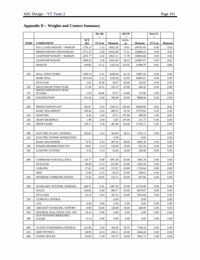
ASC Design – VT Team 2 Page 101
Appendix D – Weights and Centers Summary
Abv BL
+ Aft FP
+ Port CL
+
SWBS COMPONENT WT-MT VCG-m Moment
LCG-m Moment TCG-m Moment
FULL LOAD WEIGHT + MARGIN 2750.37 5.22 14351.26 70.81 194761.43 0.00 -9.26
MINOP WEIGHT AND MARGIN 2712.37 5.28 14322.89 71.11 192884.23 0.00 -9.26
LIGHTSHIP WEIGHT + MARGIN 2201.77 5.82 12821.21 71.79 158056.66 0.00 -9.26
LIGHTSHIP WEIGHT 2096.92 5.56 11655.64 68.52 143687.87 0.00 -8.42
MARGIN 104.85 11.12 1165.56 137.05 14368.79 -0.01 -0.84
100 HULL STRUCTURES 1180.14 5.31 6269.83 62.76 74067.26 0.00 0.00
BARE HULL 1013.64 5.12 5192.85 63.00 63859.01 0.00 0.00
PAYLOAD 5.65 10.28 58.07 63.00 355.95 0.00 0.00
150 DECK HOUSE STRUCTURE 17.58 14.55 255.75 47.00 826.35 0.00 0.00
170 MASTS+KINGPOSTS+SERV PLTFRM 2.03 26.46 53.72 63.00 127.89 0.00 0.00
180 FOUNDATIONS 141.24 5.02 709.44 63.00 8898.06 0.00 0.00
200 PROPULSION PLANT 345.97 4.35 1504.13 105.04 36340.00 -0.02 -8.42
BASIC MACHINERY 196.40 5.02 986.52 91.50 17970.60 0.00 0.00
243 SHAFTING 8.42 2.94 24.72 107.00 900.94 -1.00 -8.42
244 SHAFT BEARINGS 1.98 2.94 5.81 107.00 211.75 0.00 0.00
245 PROPULSORS 139.17 3.50 487.08 124.00 17256.71 0.00 0.00
300 ELECTRIC PLANT, GENERAL 102.03 5.53 563.69 56.51 5765.12 0.00 0.00
310 ELECTRIC POWER GENERATION 0.00 0.00 0.00
BASIC MACHINERY 73.70 5.53 407.19 69.00 5085.30 0.00 0.00
320 POWER DISTRIBUTION SYS 18.81 5.53 103.90 24.00 451.34 0.00 0.00
330 LIGHTING SYSTEM 9.52 5.53 52.60 24.00 228.48 0.00 0.00
400 COMMAND+SURVEILLANCE 118.77 8.48 1007.46 63.00 7482.20 0.00 0.00
PAYLOAD 69.20 9.72 672.85 63.00 4359.29 0.00 0.00
CABLING 27.41 5.02 137.67 63.00 1726.64 0.00 0.00
MISC 6.96 6.35 44.23 63.00 438.61 0.00 0.00
430 INTERIOR COMMUNICATIONS 15.20 10.05 152.71 63.00 957.66 0.00 0.00
500 AUXILIARY SYSTEMS, GENERAL 206.76 6.81 1407.83 55.98 11574.49 0.00 0.00
WAUX 134.60 6.46 869.77 63.00 8479.67 0.00 0.00
PAYLOAD 42.14 9.43 397.25 63.00 2654.82 0.00 0.00
510 CLIMATE CONTROL 0.00 0.00 0.00
CPS 4.94 0.00 0.00 0.00 0.00 0.00 0.00
589 AIRCRAFT HANDLING, SUPPORT 8.80 16.00 140.80 50.00 440.00 0.00 0.00
593 ENVIRON. POLLUTION CNTL SYS 10.16 0.00 0.00 0.00 0.00 0.00 0.00
598 AUX SYSTEMS OPERATING FLUIDS 6.13 0.00 0.00 0.00 0.00 0.00 0.00
600 OUTFIT+FURNISHING,GENERAL 131.99 5.94 784.26 58.70 7748.16 0.00 0.00
610 SHIP FITTINGS 68.99 6.53 450.51 63.00 4346.43 0.00 0.00
640 LIVING SPACES 63.00 5.30 333.75 54.00 3401.73 0.00 0.00

ASC Design – VT Team 2 Page 102
Abv BL
+ Aft FP
+ Port CL
+
SWBS COMPONENT WT-MT VCG-m Moment
LCG-m Moment TCG-m Moment
700 ARMAMENT 11.28 10.50 118.44 63.00 710.64 0.00 0.00
FULL LOAD CONDITION
F00 LOADS 548.60 2.79 1530.05 66.91 36704.77 0.00 0.00
F10 SHIPS FORCE 10.46 7.35 76.93 63.00 659.11 0.00 0.00
F23 ORD DEL SYS (AIRCRAFT) 10.00 14.00 140.00 54.00 540.00 0.00 0.00
F31 PROVISIONS+PERSONNEL STORES 5.20 5.25 27.31 63.00 327.47 0.00 0.00
F32 GENERAL STORES 1.94 5.95 11.53 63.00 122.16 0.00 0.00
F41 DIESEL FUEL MARINE 372.00 2.86 1064.66 69.94 26017.68 0.00 0.00
F42 JP-5 116.00 1.35 156.95 59.87 6944.92 0.00 0.00
F46 LUBRICATING OIL 19.00 1.78 33.80 87.67 1665.73 0.00 0.00
F47 SEA WATER 0.00 3.11 0.00 64.77 0.00 0.00 0.00
F52 FRESH WATER 14.00 1.35 18.87 30.55 427.70 0.00 0.00
MIN. OPERATING CONDITION
F00 LOADS 510.60 2.94 1501.69 68.21 34827.57 0.00 0.00
F10 SHIPS FORCE 10.46 7.35 76.91 63.00 658.98 0.00 0.00
F23 ORD DEL SYS (AIRCRAFT) 10.00 14.00 140.00 54.00 540.00 0.00 0.00
F31 PROVISIONS+PERSONNEL STORES 5.20 5.25 27.32 63.00 327.60 0.00 0.00
F32 GENERAL STORES 1.94 5.95 11.54 63.00 122.22 0.00 0.00
F41 DIESEL FUEL MARINE 123.00 2.06 253.38 80.83 9941.48 0.00 0.00
F42 JP-5 40.00 0.72 28.72 59.73 2389.20 0.00 0.00
F46 LUBRICATING OIL 7.00 1.43 9.98 87.58 613.06 0.00 0.00
F47 SEA WATER BALLAST 304.00 3.11 944.53 64.77 19690.08 0.00 0.00
F52 FRESH WATER 9.00 1.04 9.32 60.55 544.95 0.00 0.00
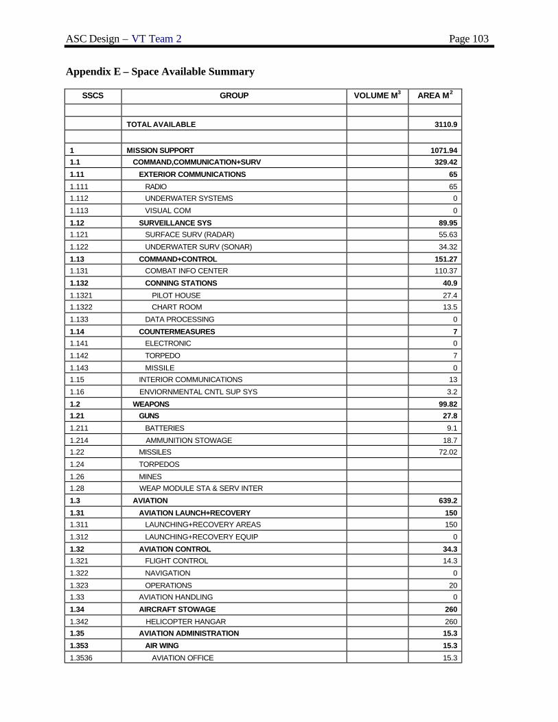
ASC Design – VT Team 2 Page 103
Appendix E – Space Available Summary
SSCS GROUP VOLUME M3 AREA M2
TOTAL AVAILABLE 3110.9
1 MISSION SUPPORT 1071.94
1.1 COMMAND,COMMUNICATION+SURV 329.42
1.11 EXTERIOR COMMUNICATIONS 65
1.111 RADIO 65
1.112 UNDERWATER SYSTEMS 0
1.113 VISUAL COM 0
1.12 SURVEILLANCE SYS 89.95
1.121 SURFACE SURV (RADAR) 55.63
1.122 UNDERWATER SURV (SONAR) 34.32
1.13 COMMAND+CONTROL 151.27
1.131 COMBAT INFO CENTER 110.37
1.132 CONNING STATIONS 40.9
1.1321 PILOT HOUSE 27.4
1.1322 CHART ROOM 13.5
1.133 DATA PROCESSING 0
1.14 COUNTERMEASURES 7
1.141 ELECTRONIC 0
1.142 TORPEDO 7
1.143 MISSILE 0
1.15 INTERIOR COMMUNICATIONS 13
1.16 ENVIORNMENTAL CNTL SUP SYS 3.2
1.2 WEAPONS 99.82
1.21 GUNS 27.8
1.211 BATTERIES 9.1
1.214 AMMUNITION STOWAGE 18.7
1.22 MISSILES 72.02
1.24 TORPEDOS
1.26 MINES
1.28 WEAP MODULE STA & SERV INTER
1.3 AVIATION 639.2
1.31 AVIATION LAUNCH+RECOVERY 150
1.311 LAUNCHING+RECOVERY AREAS 150
1.312 LAUNCHING+RECOVERY EQUIP 0
1.32 AVIATION CONTROL 34.3
1.321 FLIGHT CONTROL 14.3
1.322 NAVIGATION 0
1.323 OPERATIONS 20
1.33 AVIATION HANDLING 0
1.34 AIRCRAFT STOWAGE 260
1.342 HELICOPTER HANGAR 260
1.35 AVIATION ADMINISTRATION 15.3
1.353 AIR WING 15.3
1.3536 AVIATION OFFICE 15.3

ASC Design – VT Team 2 Page 104
SSCS GROUP VOLUME M3 AREA M2
1.36 AVIATION MAINTENANCE 119.6
1.361 AIRFRAME SHOPS 119.6
1.369 ORGANIZATIONAL LEVEL MAINTANENCE 0
1.37 AIRCRAFT ORDINANCE 0
1.372 CONTROL 0
1.373 HANDLING 0
1.374 STOWAGE 0
1.38 AVIATION FUEL SYS 150 0
1.381 JP-5 SYSTEM 150 0
1.3811 JP-5 TRANSFER
1.3812 JP-5 HANDLING
1.3813 AVIATION FUEL 150
1.39 AVIATION STORES 60
1.8 SPECIAL MISSIONS
1.9 SM ARMS,PYRO+SALU BAT 3.5
1.91 SM ARMS (LOCKER) 3.5
1.92 PYROTECHNICS
1.93 SALUTING BAT (MAGAZINE)
1.94 ARMORY
1.95 SECURITY FORCE EQUIP
2 HUMAN SUPPORT 1135.65
2.1 LIVING 776.72
2.11 OFFICER LIVING 164.17
2.111 BERTHING 128.45
2.1111 SHIP OFFICER 128.45
2.1111104 COMMANDING OFFICER STATEROOM 17.4
2.1111206 EXECUTIVE OFFICER STATEROOM 16.5
2.111123 DEPARTMENT HEAD STATEROOM 25.27
2.1111302 OFFICER STATEROOM (DBL) 69.28
2.1114 AVIATION OFFICER
2.112 SANITARY 35.72
2.1121 SHIP OFFICER 35.72
2.1121101 COMMANDING OFFICER BATH 2.77
2.1121201 EXECUTIVE OFFICER BATH 2
2.1121203 OFFICER BATH 25.85
2.1121303 DEPT HEAD BATH 5.1
2.1124 AVIATION OFFICER
2.12 CPO LIVING 117.2
2.121 BERTHING 89.4
2.122 SANITARY 27.8
2.13 CREW LIVING 486.75
2.131 BERTHING 404.73
2.132 SANITARY 62.72
2.133 RECREATION 19.3
2.14 GENERAL SANITARY FACILITIES 3
2.142 BRIDGE WASHRM & WC 2
2.143 DECK WASHRM & WC 0

ASC Design – VT Team 2 Page 105
SSCS GROUP VOLUME M3 AREA M2
2.144 ENGINEERING WR & WC 1
2.15 SHIP RECREATION FAC 0
2.151 MUSIC
2.152 MOTION PIC FILM+EQUIP
2.153 PHYSICAL FITNESS
2.154 TV ROOM
2.16 TRAINING 5.6
2.2 COMMISSARY 270.3
2.21 FOOD SERVICE 131.03
2.211 WARDROOM MESSRM & LOUNGE 28.62
2.212 CPO MESSROOM AND LOUNGE 40.41
2.213 CREW MESSROOM 62
2.22 COMMISSARY SERVICE SPACES 46.27
2.221 FOOD PREPARATION SPACES
2.222 GALLEY 37.46
2.2222 WARD ROOM GALLEY 8.81
2.2224 CREW GALLEY 28.65
2.223 WARDROOM PANTRY 0
2.224 SCULLERY 8.81
2.23 FOOD STORAGE+ISSUE 93
2.231 CHILL PROVISIONS
2.232 FROZEN PROVISIONS
2.233 DRY PROVISIONS
2.3 MEDICAL+DENTAL 9.5
2.4 GENERAL SERVICES 34.08
2.41 SHIP STORE FACILITIES 12.28
2.42 LAUNDRY FACILITIES 21.8
2.44 BARBER SERVICE
2.46 POSTAL SERVICE
2.47 BRIG
2.48 RELIGIOUS
2.5 PERSONNEL STORES 40
2.51 BAGGAGE STOREROOMS 20
2.52 MESSROOM STORES 10
2.55 FOUL WEATHER GEAR
2.56 LINEN STOWAGE 10
2.57 FOLDING CHAIR STOREROOM
2.6 CBR PROTECTION 0
2.61 CBR DECON STATIONS
2.62 CBR DEFENSE EQUIPMENT
2.63 CPS AIRLOCKS
2.7 LIFESAVING EQUIPMENT 5.05
3 SHIP SUPPORT 623.43
3.1 SHIP CNTL SYS (STEERING) 15.5
3.11 STEERING GEAR 15.5
3.12 ROLL STABILIZATION
3.15 STEERING CONTROL

ASC Design – VT Team 2 Page 106
SSCS GROUP VOLUME M3 AREA M2
3.2 DAMAGE CONTROL 38.1
3.21 DAMAGE CNTRL CENTRAL 14.1
3.22 REPAIR STATIONS 14
3.25 FIRE FIGHTING 10
3.3 SHIP ADMINISTRATION 101.55
3.301 GENERAL SHIP 25.24
3.302 EXECUTIVE DEPT 16.9
3.303 ENGINEERING DEPT 11.27
3.304 SUPPLY DEPT 16.2
3.305 DECK DEPT 25.24
3.306 OPERATIONS DEPT 6.7
3.307 WEAPONS DEPT
3.31 SHIP PHOTO/PRINT SVCS
3.5 DECK AUXILIARIES 25.8
3.51 ANCHOR HANDLING 25.8
3.52 LINE HANDLING
3.53 TRANSFER-AT-SEA
3.54 SHIP BOATS STOWAGE
3.6 SHIP MAINTENANCE 196.48
3.61 ENGINEERING DEPT 35.14
3.611 AUX (FILTER CLEANING)
3.612 ELECTRICAL DIV SHOP 11.47
3.613 MECH (GENERAL WORKSHOP) 13.6
3.614 PROPULSION MAINTENANCE 10.07
3.62 OPERATIONS DEPT 7.9
3.63 WEAPONS DEPT (MISSIONS SHOP) 120
3.64 DECK DEPT 33.44
3.7 STOWAGE 60
3.71 SUPPLY DEPT
3.711 HAZARDOUS MATL (FLAM LIQ)
3.712 SPECIAL CLOTHING
3.713 GEN USE CONSUM+REPAIR PART
3.714 SHIP STORE STORES
3.715 STORES HANDLING
3.72 ENGINEERING DEPT
3.73 OPERATIONS DEPT
3.74 DECK DEPT (BOATSWAIN STORES)
3.75 WEAPONS DEPT
3.76 EXEC DEPT (MASTER-AT-ARMS STOR)
3.78 CLEANING GEAR STOWAGE
3.8 ACCESS 186
3.82 INTERIOR 186
3.821 NORMAL ACCESS 180
3.822 ESCAPE ACCESS 6
3.9 TANKS 621
3.91 SHIP PROP SYS TNKG 464
3.911 SHIP ENDUR FUEL TNKG 464
3.9111 ENDUR FUEL TANK (INCL SERVICE) 464
3.914 FEEDWATER TNKG

ASC Design – VT Team 2 Page 107
SSCS GROUP VOLUME M3 AREA M2
3.92 BALLAST TNKG 125
3.93 FRESH WATER TNKG 14
3.94 POLLUTION CNTRL TNKG 18
3.941 SEWAGE TANKS 8
3.942 OILY WASTE TANKS 10
3.95 VOIDS
3.96 COFFERDAMS
3.97 CROSS FLOODING DUCTS
4 SHIP MACHINERY SYSTEM 138 279.88
4.1 PROPULSION SYSTEM 49.93
4.13 INTERNAL COMBUSTION (DIESEL) 0
4.132 COMBUSTION AIR (INTAKE)
4.133 EXHAUST
4.134 CONTROL
4.14 GAS TURBINE 49.93
4.142 COMBUSTION AIR (INTAKE) 18.9
4.143 EXHAUST 18.47
4.144 CONTROL 12.56
4.2 PROPULSOR & TRANSMISSION SYST 138 55.4
4.23 WATERJET ROOMS 138 46
4.23001 PROP SHAFT ALLEY 46
4.24 AIR FAN ROOMS 9.4
4.3 AUX MACHINERY 174.55
4.32 A/C & REFRIGERATION 46.1
4.321 A/C (INCL VENT)
4.322 REFRIGERATION
4.33 ELECTRICAL 95.57
4.331 POWER GENERATION 90
4.3311 SHIP SERVICE PWR GEN 90
4.3313 BATTERIES
4.3314 400 HERTZ
4.332 PWR DIST & CNTRL 5.57
4.334 DEGAUSSING
4.34 POLLUTION CONTROL SYSTEMS 32.88
4.341 SEWAGE 29
4.342 TRASH 3.88
4.35 MECHANICAL SYSTEMS
4.36 VENTILATION SYSTEMS

ASC Design – VT Team 2 Page 108
Appendix F - MathCAD Model (Add)