Embed Size (px)
Citation preview

Design Platform for Planar Mechanisms based on a Qualitative Kinematics
Bernard Yannou
Adrian Vasiliu
Abstract: Our long term aim is to address the openproblem of combined structural/dimensional synthesis forplanar mechanisms . For that purpose, we have developed adesign platform for linkages with lower pairs which isbased on a qualitative kinematics . Our qualitativekinematics is based on the notion of Instantaneous Centersof Velocity, on considerations of curvature and on amodular decomposition of the mechanism in Assur groups .A qualitative kinematic simulation directly generatesqualitative trajectories in the form of a list of circular arcsand line segments . A qualitative simulation amounts to apropagation of circular arcs along the mechanism from themotor-crank to an effector point. A general understandingof the mechanism, independent of any particulardimensions, is extracted . This is essential to tacklesynthesis problems . Moreover, we show that adimensional optimization of the mechanism based on ourqualitative kinematics successfully competes, for the pathgeneration problem, with an optimization based on aconventional simulation.
1 Introduction
Mechanical linkages with lower pairs are planarmechanisms of fixed topology, consisting of rigid bodiesconstantly connected with joints of revolute type (allowinga rotation) or prismatic type (allowing a translation) . Anexample is given in Fig. 1 . Linkages with lower pairsrepresent a large part of the existing mechanisms inindustry . Our subject is to develop an efficient automatic orsemi-automatic method for the synthesis of these linkages .Such a method should find one or several optimalmechanisms submitted to functional requirements . Theserequirements are conventionally:
"
thedesired kinematics of one or several bodies," no collision between the mechanism and its
environment,"
the minim;zation of the efforts in joints when the twoprevious criteria are fulfilled.
For the moment, we have limited our research to:" linkages of one-degree-of-freedom,
Laboratoire Productique LogistiqueEcole Centrale Paris
92295 Chatenay-Malabry, France
phone +33 141131285
fax +33 141131272email [yannou I adrian]@cti.ecp .fr
)out nFigure 1 : Example of a linkage, composed of a slider-crankmechanism (bodies 1, 2 and 3) and a dyad (bodies 4 and 5) . Joints Aand G are revolute joints (rotation) connected to the fixed frame .Joint D is a prismatic joint connected to the fixed frame . Theother joints are revolute joints connecting two bodies . There is amotor atjoint A, so body 1 is a crank
a requirement of desired kinematics in the form of thedesired trajectory of a point, termed effector point, ona body of the mechanism, making abstraction of theorientation of this body. This problem is called thepath generation problem.
A synthesis process consists of choosing the type ofmechanism (type synthesis), e.g ., slider-crank or four-barmechanism, and the optimal dimensions for this mechanism(dimensional synthesis) . The dimensional synthesisproblem has been widely studied for two decades and more[13 ; 25], and some satisfactory techniques have beenimplemented . However, the combined type/dimensionsynthesis problem remains an open problem for two majorreasons . On one hand, it often consists in testing a hugenumber of simple equivalent mechanisms in terms of aunique criterion: the number of degrees of freedom [12; 24 ;26] . On the other hand, the criteria which preside over thepruning of such a combinatory are completelyquestionable . In fact, the choice of the type of mechanism isvery little constrained by the requirements and, for a giventype of mechanism, there is no classification of thetrajectories in terms of the dimensions. This reveals that atpresent we have very poor and unstructured knowledgeabout the interactions between functions, structures anddimensions for the mechanisms.
It is for this reason that we developed a platform for thedesign of linkages which is based on a qualitative

kinematics . The idea of this qualitative kinematics is toconsciously accept a small loss in numerical accuracy oftrajectories, in order to handle more global and qualitativeinformation and to have a deeper understanding ofmechanisms . This is made by directly generating qualitativetrajectories in the form of lists of circular arcs and linesegments, instead of generating lists of points like in aconventional simulation .
Firstly, we show that a dimensional optimization(synthesis) process based on (looping over) such aqualitative kinematic simulation is faster than anoptimization process based on a conventional simulation.For brevity, we will term these two dimensionaloptimization processes : qualitative optimization and exact(or conventional) optimization . Secondly, and this is thereal challenge, we show how to construct a qualitativeunderstanding of a mechanism as an engineer could do, inorder to justify the qualitative shape of the trajectory fromparticular dimensions . Only the work of Shrobe [27] dealswith this purpose but in a less explicit manner . Thequalitative explanations that our system generates use twomechanisms of causal deductions : a modular decompositionof the mechanism and a causal graph of InstantaneousCenter of Velocityl calculations. Thirdly, we hope that, inthe long term, we shall be able to invert the explanationprocess . Then, we would be able, in a combinedtype/dimension synthesis process, to intelligently indexsome mechanism types which are serious candidates and todirectly propose value intervals for the dimensions .
Section 2 presents the two functionalities of the designplatform : generation of the qualitative explanations andqualitative optimization . We evoke, in section 3, themodular decomposition of a mechanism and its advantages .In section 4, we present our qualitative kinematics . Section5 shows how our qualitative kinematics can be applied toa dimensional optimization . The most important section issection 6 where we show how to construct qualitativeexplanations for a mechanism. Finally, in section 7 wecompare our work with others on qualitative kinematics.
2
The two functionalities of the designplatform
2.1
Qualitative explanations and qualitativedimensional optimization
Both functionalities of the design platform (generation ofthe qualitative explanations and qualitative optimization)require as a first step an approximation of an exacttrajectory (in the form of a list of points) into a qualitativetrajectory (in the form of a list of arcs and segments) . Inboth cases, this resulting qualitative trajectory is used todrive a qualitative kinematic simulation.
1 Henceforward, they are termed ICs.
In the case of the generation of qualitative explanations,the exact trajectory is generated by a primaryconventionalkinematic simulation for specific dimensions of themechanism which must be explained . This is the trajectoryof the effector point which intervenes in the specification,i.e ., in the function of the mechanism, so that we can saythat the sought function drives the explanations . Theprocess of the generation of the qualitative explanations issummed up in Fig. 2-
Figure 2 : Generating qualitative explanations of the behaviour ofa mechanism .
In the case of qualitative optimization (which is a loopover a qualitative kinematic simulation), the exacttrajectory is specified by the designer himself because thisis the desired trajectory to fulfill . After a qualitativedimensional optimization, optimal dimensions for themechanism are proposed : this is the qualitative optimum(see Fig . 3) . In order to confirm the validity ofour approach(in spite of the two consecutive approximations : firstapproximation into arcs and segments and qualitativesimulation), we will have to compare the qualitativeoptimum with the exact optimum directly obtained by aconventional optimization .
'Mechanism type'WITHOUT any
specific dimension
EXACTdesired traj.
Approximationinto arcs and
QUALITATIVEsegments
d6sired traj .
VALIDATION QUALITATIVEoptimum
Figure 3 : Qualitative dimensional optimization . The methodremains to be validated by comparison between the qualitativeand the exact optima .
2.2
Approximation of an exact trajectory intoarcs and segments
This approximation takes as input argument a maximumadmissible error. This error is the maximum distance

3
Modular decomposition of linkages
Figure 4: Approximation of an exact trajectory (left) defined by 48points into a qualitative trajectory (right) defined by 4 circulararcs .
between a point of the exact trajectory and the qualitativetrajectory. A minimization of the total number of arcs andsegments is carried out with a least square algorithm . Forthe same total number of arcs and segments, the maximumnumber of segments is preferred because they have moresignificant qualitative properties . Finally, the thirdcriterion is to prefer the approximation which minimizesthe error . The algorithm does not respect the continuitybetween the arcs (and segments) because it is not necessary.An example of approximation is given in Fig. 4 .
Modular decomposition of linkages is an efficientapproach for linkage analysis and a way to betterunderstand a mechanism [4;10;17] . It consists in dividingthe mechanism into elementary structural groups, calledAssur groups . An Assur group is obtained from a kinematicchain of zero mobility by suppressing one or more links, atthe condition that there is no simpler group inside .Theoretically, the number of Assur groups is not limited,but practically only the simplest are used .An interesting extension of the theory of Assur groups
consists in a systemic view of the modular approach .Pelecudi [20; 21] extended the notion of Assur group to theconcept of a multipole group as an elementary sub-systempossessing input poles (joints), motion and effort transferfunctions, internal poles and output poles (see Fig. 5) . Inputand output poles are considered as potential joints,allowing connection with other groups . We haveimplemented in our platform an algorithm for the automaticmodular decomposition of linkages . This decomposition isunique (see Fig. 6) .A kinematic simulation consists in looping over a
configuration determination corresponding to a particularcrank angle . During a configuration resolution, each group,
Figure 5 : Examples of the simplest Assur groups and thecorresponding systemic icons .
Figure 6: A systemic representation of the linkage of Fig . 1 by amodular decomposition into multipole groups.
considered as a sub-system, receives from the previousgroup information about the position, velocity andacceleration of its input joints . After an internalcalculation according to the transfer function of the group,the kinematic features of the output poles are determinedand transmitted to the next group.
Thus, a configuration resolution can be viewed as amotion propagation from the fixed frame to the terminalgroup . In normal situations, the terminal group contains theeffector point in order for each group to contribute to theposition and velocity of the effector point . Otherwise, thesuperfluous groups must certainly have another function inthe mechanism and the motion of their internal poles willbe interesting for future qualitative explanations. This isthe case of the linkage in Fig . 1 with an effector point in E ;point F (see Fig . 6) is detected as an interesting point forexplanations .
The transfer function is known a priori for each type ofAssur group. For most of the simpler groups, the position,velocity and acceleration of the output poles are expressedin an explicit manner from the kinematic features of theinput poles. Such a modular decomposition is a systematicapproach to reduce iterative calculations for any type oflinkages . It can be considered as a symbolic compilation ofthe mechanism, depending only on its type and not on itsparticular dimensions . It allows a kinematic simulationmethod which is more efficient than computing and solvingequations for the whole mechanism at once . It can helpkinematic (and also kinetostatic) analysis, but alsosynthesis (for more details, see [30]) .
In our platform, the modular decomposition will be usedfor a resolution in positions (not in velocities) inside aqualitative kinematic simulation .
4
The qualitative kinematicsimulation
The qualitative kinematic simulation is the basis of ourwork. In very few iterations (corresponding to the number
` a ¬ o~
save
, ALN t ~
eC
-
o

of arcs and segments), it generates a "rough" simulation interms of numerical accuracybut its interest is double :
"
to obtain a good elementary calculus time inside adimensional optimization process,
to build qualitative explanations of mechanismbehaviour .
This qualitative simulation is based on the notions ofInstantaneous Centers of Velocity (ICs) and some notions ofcurvature in plane kinematics.
4.1
An approach based on the InstantaneousCenters (ICs)
During the movement of a mechanism, it can beconsidered that the relative movement between any coupleof bodies (say i and j) is locally2 equivalent to a rotationof center IC;I . This is the Instantaneous Center of Velocity
between the bodies i and j. Of course, if bodies i and j areconnected by a revolute joint, IC;I is constantly the center
of the joint, fixed relatively to body i and body j .Otherwise, IC;I changes over time . In like manner, a
prismatic joint between bodies i and j, is kinematicallyequivalent to a revolute joint whose the relative IC is atinfinity in a direction Dy orthogonal to the direction of
translation . Traditionally, the ICs are used in graphicalmethods to calculate a specific absolute velocity (relativeto the fixed frame 0) or a relative velocity between twobodies, starting from the known velocity of the motor-crank as in the one-degree-of-freedom mechanism of Fig. 1 .A remarkable property of these ICs is given by the theoremof three centers:
The relative ICs of any three bodies: ICij , ICIk and
IC ik lie on the same straight line.
Now, let us consider a particular position of the motor-crank for which the rotational velocity is known. Let usdenote M a point on the motor-crank, hence its velocityvector is supposed to be known. The IC between the fixedframe (0) and the motor-crank (M, too), denoted ICOM , is
constantly the center of the fixed revolute joint . Let usdenote T, standing for trajectory, the effector point and, byextension, the body where it is attached . The knowledge,for a particular crank position, of the positions of theeffector point and ICs : 1CMT and ICpT , leads to the
calculus of the velocity vector of the effector pointrelatively to the fixed frame, as explained in Fig . 7. Thesetwo interesting ICs are not a priori known .
It is worth knowing that when ICMT and 1COM are
geometrically equal, the effector point has a zero velocity(it locally stands still) .
2 "Locally" means during an infinitesimal period oftime.
Figure 7: Calculation of the effector point velocity vector.Graphically, the method is simple: the velocity vector of Mand vector a have the same norm, the velocity vector of theeffector point T and vector c too . Vectors. a, b and c areorthogonal to the straight line of the ICs.
We have developed an algorithm which provides themethod to determine the unknown ICs from the known ICsby using the theorem ofthree centers and with a minimum ofintermediary ICs . According to the theorem of three centers,two known ICs : 1Cil ,and ICIk define the straight line
where lies ICik , termed AlCik . In like manner, a known IC :IC& and a direction Dij coming from a prismatic joint,
define a straight line AICik . The elementary step of thealgorithm is the determination of a new IC lCik byintersection of two known straight lines AlCik .
Let us take the mechanism of Fig . 1 and suppose that thepositions of the joints are known. Hence, six ICs are
already known from a total of fifteen (C6 ) : ICON is joint A,
'Cl 2 is joint B, IC23 is joint C, IC24 is joint E, IC45 is jointF, ICo5 is joint G. The effector point is E and an interestingpoint is F (see also §6) . These points are both fixed to body4 . We saw that we were to determine ICMT and ICOT , i .e.in our case : IC14 and ICp4 . For this case, only oneintermediary IC turns out to be necessary : 1C02 . Thealgorithm proceeds in two steps : building first a causalgraph of IC deductions (see Fig . 8 .a) and, from this graph,generating a symbolic trace of IC deductions (see Fig . 8 .b) .This trace respects the sequentiality of the IC calculations,i .e., at any moment the calculation of a new IC is carriedout from previously known or calculated ICs . The methodof IC determination can be graphically displayed to the
ICo2 = (ICo1,ICI2)n (Dos ,IC23
IC04 =(ICo2 ,IC 24 )n(ICp5 ,IC45 )
(b) IC14 =(ICo1,ICo4 )n(ICi2 ,IC24 )
Figure 8 : An IC causal graph (a) and the corresponding symbolictrace (b) which shows the order of IC calculations .
joint D
Figure 9 : Method of determination of the sought ICs for themechanism ofFig. 1 .
designer (see Fig. 9). This algorithm of IC determination isapplied once for a mechanism type and a given effectorpoint; it is independent of any specific dimensions . Thesymbolic trace of deductions is used for automaticallygenerating the coordinate equations of the sought ICs andthe velocity vector equations of points E and F (asexplained in Fig . 7) in a symbolic form . In this manner,velocity vectors are calculated without any iteration andby the call to an optimized procedure . Like for the modulardecomposition, it can be said that the mechanism is1.compilated" . The fact that there is no iteration for thedetermination ofvelocity in a general case of mechanism isa good result from the point of view of speed . Even themodular approach of Assur groups does not escape toiterative calculations of the velocity for some (rare) Assurgroups .
4.2
Curvature of qualitative arcs and centrodes
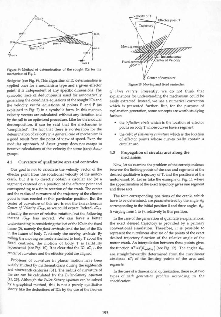
Our goal is not to calculate the velocity vector of theeffector point from the rotational velocity of the motor-crank, but it is to directly obtain a circular arc (or asegment) centered on a position of the effector point andcorresponding to a finite rotation of the crank . The centerand the radius of curvature of the trajectory of the effectorpoint is thus needed at this particular position . But thecenter of curvature of this arc is not the InstantaneousCenter of Velocity ICoT , as we could expect . Indeed, ICoTis locally the center of relative rotation, but the followinginstant 'COT has moved. We can have a betterunderstanding in considering the loci of the ICs in the fixedframe (0), namely thefixed centrode, and the loci of the ICsin the frame of body T, namely the moving centrode . Byrolling the moving centrode attached to body T about thefixed centrode, the motion of body T is faithfullyrepresented (see Fig . 10) . It is clear that the IC : ICOT , thecenter of curvature and the effector point are aligned .Problems of curvature in planar motion have been
widely studied by mathematicians during the eighteenthand nineteenth centuries [31] . The radius of curvature ofthe arc can be calculated by the Euler-Savary equation[13; 25] . Although the Euler-Savary equation can be solvedby a graphical method, this is not a purely qualitativetheory like the deductions of ICs by the use of the theorem
Figure 10 : Moving and fixed centrodes .
of three centers. Presently, we do not think thatexplanations for understanding the mechanism could beeasily extracted . Instead, we use a numerical correctionwhich is presented further . But, for the purpose ofexplanation generation, some concepts are worth studyingfurther :
the inflection circle which is the location of effectorpoints on body T whose curves have a segment,
the cubic of stationary curvature which is the locationof effector points whose curves really contain acircular arc.
4.3
Propagation of circular arcs along themechanism
Now, let us examine the problem of the correspondencebetween the limiting points of the arcs and segments of thedesired qualitative trajectory of T, and the positions of themotor-crank M. Let us take the example of Fig. 11 wherethe approximation of the exact trajectory gives one segmentand three arcs .
The four corresponding positions of the crank, whichhave to be determined, are parameterized by the angle 00corresponding to the initial position 0 and three angles 00i(i varying from 1 to 3), relatively to this position .
In the case of the generation of qualitative explanations,the exact desired trajectory is provided by a primaryconventional simulation. Therefore, it is possible torepresent the curvilinear abscissa of the points of the exactdesired trajectory function of the relative angle of themotor-crank. An interpolation between these points givesthe function ST = f(Breiative ) (see Fig . 12) . The angles Bp ;
are straightforwardly determined from the curvilinearabscissas sTi of the limiting points of the arcs andsegments.
In the case of a dimensional optimization, there exist twotypes of path generation problem according to thespecification:

0,4
Figure 11 : What is the correspondence between the limitingpoints of the arcs and segments of the desired qualitativetrajectory of T and the positions of the motor-crank ?
" The effector point must move along the desiredtrajectory in accordance with prescribed temporalpositions ofthe crank . It amounts to impose the curvesT = f(B,elarive~~ i.e . angles 0oi corresponding to sT .If this curve is the straight line ((0,0),(2tr,ST,. )), itmeans that the curvilinear velocity of the effectorpoint and the angular velocity of the motor-crank areproportional . The designer can also define areas ofrelatively high acceleration or deceleration for theeffector point .
The effector point must move along the desiredtrajectory whatever the corresponding positions ofthe crank may be . Thus, angles do and B oi becomedesign variables which are to be valued during theoptimization process . This represents the generalcase .
Now, let us consider the mid-points M; of the circulararcs of the trajectory of M (see Fig . 13 .b) and the mid-pointsTi of the circular arcs and line segments of the qualitativedesired trajectory (see Fig. 13.a) .
In saying that points T temporally correspond to pointsMi , we commit a piecewise linear approximation of thecurve sT = f ( B,eiative
(compare Fig . 14 and Fig . 12) . In fact,the effector is considered to move with a constant velocityalong a circular arc (for a constant rotational velocity ofthe motor-crank) . Again, this acceptable approximationconfirms that we construct a qualitative kinematics .
sTsTmax
ST3
sT2
00
001 002 003 27t
0relative
Figure 12: The knowledge of the curve ST = f ( e,eiative
leadsto the determination of angles 9oi .
Figure 13 : (a) Arcs and segments of the qualitative trajectory ofthe effector point T . (b) Arcs of the qualitative trajectory of pointM attached to the motor-crank .
From now, we will consider, at the inverse, a qualitativekinematic simulation where the circular arcs of the currenttrajectory of the effector point must be calculated from thecircular arcs of the motor-crank . For each position of themotor-crank in M; (the mid-point of a circular arc), aresolution of positions is carried out, using the graph ofmodular decomposition ; the positions of the effector pointT; and the positions of the joints are then determined . Thevelocityvector of the effector point V(Ti) is determined bythe specific procedure generated from the symbolic trace ofIC deductions . This vector gives the orientation and thelength of the arc centered on Ti . Indeed, benefiting from thefact that the ratio of the curvilinear velocities are constanton an arc, the curvilinear total lengths of the twocorresponding arcs respect the same ratio . Thus, wedirectly consider that the velocity values are equal to thecurvilinear length values . At present, the determination ofthe radius of curvature is solved by a second positionresolution of the mechanism very close from the mid-pointof the arc Ti . It can be seen in Fig . 10 that this secondposition is sufficient because we already know the straightline (ICOT ,Ti ) where the center of curvature lies .
The deduction of the velocities from the motor-crank tothe effector point through multiple ICs can be viewed as apropagation of a velocity vector through the mechanism .Therefore, since a velocity vector and a circular arc aresomewhat equivalent (except for the radius of curvature),
sTsTaux
sT3
sT2
sTiT10
0
M1 001 002 003 2n
0relative
Figure 14 : The piecewise linear approximation which is madebecause of the use of qualitative arcs and segments (to becompared with the original curve in Fig. 12).

the image of the propagation of circular arcs from themotor-crank to the effector point can be adopted .
5
Dimensional optimization based onqualitative kinematics
In this section, our concern is to dimensionally optimizea given mechanism for the path generation problem, i .e . tofind the best dimensions in order for an effector point tomove along a desired trajectory .
Several types of methods are currently used: graphicaltechniques [13 ; 25], direct analytical methods [2] andoptimization techniques (non-linear programming) [l ; 3; 4;11 ; 18 ; 24; 28 ; 32] . A major drawback in using analyticalmethods is that the number of prescribable points 3 of thedesired trajectory is limited by the type of mechanism .Therefore, for a large class of practical design problems,we need optimization methods, which represent a generaldesign tool . However, this is a hard problem especiallybecause of its high non-linearity .
After having specified an exact desired trajectory, thedesigner approximates it into a qualitative desiredtrajectory (let us take the example of Fig . 4) . Next, thedesigner chooses a mechanism type (the one of Fig . 1) andspecifies the effector point (E) and the design variableswhich can vary in the optimization process. By default, thecoordinates of revolute joints and the angles of prismaticjoints, corresponding to the initial configuration of themechanism, are design variables . The coordinates of theeffector point are not design variables because the effectorpoint is constrained to be at the position 0 of the desiredtrajectory . The bar lengths are deduced from thesevariables . Moreover, angles eo and Bp i of the motor-crank, corresponding to the qualitative desired trajectory,must be added, when no temporal constraint is specified onthe motion of the effector point . In the example of Fig . 1, itcan be deduced from the modular decomposition of Fig . 6that the dyad group composed by bodies 4 and 5 does notintervene in the motion of the effector point E. The generaldesign vector is then:
(XA , YA ,XB,YB,XC,YC,aD,Bo,eot,e02,eo3)
Here, an important advantage of the qualitativeapproach is that the number of variables of angles ( eo and9oi ) is equal to the number of qualitative arcs (andsegments) . For a conventional approach, this numberwould have been equal to the number of points of thedesired trajectory . In the example of Fig . 4 .b and 4.a, thesenumbers are respectively 4 and 48 .In fact, for a conventional approach with numerous
precision points, another technique is used to avoid thisdesign variable explosion. The aim is to make abstractionof any temporal correspondence between the two
3 We find also in the literature : precision points .
trajectories, only the final curves are then compared . In[11], for example, the calculated trajectory is interpolatedby a spline for each simulation and is compared to thespline interpolation of the desired trajectory . The penaltyfunction between the two trajectories is the sum of squaresof two sets of points equally spaced along each spline . But,these interpolations are extremely costly. Therefore, in ourqualitative approach, we prefer to have, for the sake ofefficiency, a few additional design variables for the crankangles and to perform a one-to-one comparison between thetwo lists of arcs and segments . The cost due to the distancebetween the desired and the simulated trajectories takesinto account the coordinates of the limiting points A and Cof the arcs and segments and their mid-points B, accordingto the formula:
w1Foist
Nb . arcs rcs
2['((XAd -X'4512+ (YAd YAS)
2)+,'
(( XBd -XBs )2 +(YBd -YBs) 2 )+
2 (IXCd -XCs,2+(YCd -YCS
)2)
The factor 1 for the limiting points comes from the fact2
that these points are counted twice, in two neighbour arcsor segments . Even if they are not identical because of thenon-continuity, they correspond logically to the same pointon the desired trajectory, so they must be counted onlyonce . wt is a weight coefficient.
The optimization algorithm must penalize themechanisms which encounter blocking positions during asimulation. For that purpose, we propose a penalty termwhich is proportional to the square of the differencebetween the curvilinear length of the desired trajectory(Ld ) and the curvilinear length of the simulated trajectory(Ls) . When, during a simulation, a blockage is encountered,the simulation is rerun backwards in order to obtain themaximum value for Ls . So, we have a penalty term :
Fblock = w2 (Ld-Ls )2 .
Finally,
the
term
Fconstr
isintroduced in order to take into account user definedconstraints such as : the linkage must never cross adelimiting box, one bar length must be lower than a value,and so on. So, the global penalty function is :
F =Fdlst +Fblock +Fconstr
We adopted an optimization algorithm based on thegradient method because of the non-accessibility to partialderivatives, the non-linearity and inequality constraints .Anyway, the choice of the optimization algorithm turns outto be almost independent from the type of kinematicsimulation (qualitative or not) . For the example of Fig. 1(11 design variables), the use of a qualitative simulationinstead of a conventional simulation speeds up theoptimization, practically with a factor of two, whichcorresponds the speed ratio between two simulations ofdifferent type . Indeed, instead of dealing with a description

86 72 198 144 188 216 a2 see 124 369
Figure 15: The curve of the angle of body 5 (see Fig . 1)as a function of the angle of the motor-crank exhibits aperiod of constant angle named a dwell.
of the desired trajectory by a collection of points,qualitative simulation deals with a much smaller number ofarcs and segments while at the same time almost faithfullyreproducing the exact curve when the mechanism reachesideal dimensions. Finally, we have confirmed, on severalexamples, the validity of our model of qualitativeoptimization in finding a qualitative optimum very close totheexact optimum
6
Understanding linkagesThe title of this section is deliberately the same as an
article by Shrobe [27] . Below, we will compare bothapproaches of understanding linkages . Presently, let ustake again the mechanism of Fig. 1 . The effector point isjoint E and its exact trajectory is given in Fig . 4.a . Thisexact trajectory is approximated into four circular arcswith a high degree of accuracy (see Fig. 4 .b). The mechanismexhibits the same phenomenon as the mechanismof Shrobe'sarticle, namely a dwell. Indeed, observing the curve of theangle of body 5 as a function of the crank angle (see Fig .
90
87
81
7s
69
62
u
49
Figure 16: Our system exhibits graphically the necessarycondition to have a dwell-mechanism: three straight linesattached to bodies must be concurrent.
15), we notice that body 5 stands still during a rotation ofthe motor-crank of about 140° ; this is the dwellphenomenon .
This is due to the fact that when the effector point ismoving along arc A3 (see Fig . 16), the length of body 4 issuch that joint F is constantly at the center of curvature ofarc A3. Our system does not only describes thisphenomenon but it also explains why it occurs for theparticular dimensions of the mechanism . This is anessential difference with the workby Shrobe .
Joint F was, for us, an interesting point. When we try todetermine the velocity of joint F, for the positioncorresponding of the mid-point of arc A3 : T3 , we fall on theparticular case (see Section 4.1) where /C45 and IC04 aregeometrically equal, i.e . the distance is lower than a fixedadmissible distance. Thus, we have proved symbolicallythat body 5 stands still locally for the positioncorresponding to T3 . This is a necessary condition forbody 5 to stand still for a period of time (dwell) . Thesecond necessary condition is that the center of curvatureis also geometrically identical IC45 (joint F), which isimmediately shown . Concerning the first condition, oursystem is capable of generating many more relevantexplanations, in explaining why, in this particularposition, the dimensions of the mechanism caused /C45 andIC04 to be geometrically equal . According to the causalgraph of ICs, we know that 1C04 is obtained by:
ICo2 =(1Co1 ,IC12)"') (Do3 ,IC23)
ICo4 =(/Cp2 ,IC24)n(ICo5 , IC45)
With IC45 and IC04 identical, the system infers, aftersome symbolic handling, that the three straight lines(1Co1,1C12 ), (IC45 ,/C24 ) and (D03,lC23) are concurrent atthe same point ICo2 . This result is presented graphically tothe designer which understands that: " the bar of body 1, thebar of body 4 and a vertical bar passing through joint C arenecessarily concurrent " (see Fig . 16).
From particular dimensions of a mechanism of a giventype, we have extracted a general understanding of thismechanism and we have given dimensional conditions torespect in order to perform the dwell function . This lastfeature is not implemented by Shrobe . However, thisgeneralization of the knowledge linking type, dimensionsand functions is an essential condition to efficiently tacklethe problem of combined type/dimension synthesis .
7
Related worksOur work addresses both the domain of linkage
synthesis and the domain of qualitative-kineiiatics.- Wealready stated (in the introduction), that the recent workson a combined type/dimension synthesis of linkages [24;28] were not satisfactory because of the poorness of theknowledge about the interactions between mechanical

functions, mechanism types and mechanism dimensions .This is why we developed a qualitative kinematics toextract general explanations on the mechanism behaviourfrom particular dimensions .
The two primary major approaches in qualitativekinematics were those of Joskowicz & al [14;15;16;19 ; 22;23] and Faltings & al [5; 6 ; 7 ; 8; 9] . The two approaches arevery similar in principle :
they are dedicated to mechanisms of changingtopologies, with contacts of complex shapes,
"
the configuration space of a mechanism is defined bycombining both quantitative and symbolicinformation,
" a qualitative kinematic simulation consists inforecasting the state transitions, i .e. changes in thetopology (a contact is established or broken) .
On one hand, Joskowicz & al consider three-dimensionalmechanisms with fixed axes ; on the other hand, Faltings &al consider two-dimensional (or planar) mechanisms oftwo degrees of freedom like a pawl and ratchet [6; 7], orclocks [9] .
In [7], Faltings and Sun began to explore therelationships between the part dimensions and thekinematic functions . Given a mechanism and some initialdimensions, theypropose a technique to redesign the systemwith new dimensions in order to meet functionalrequirements .
Subramanian and Wang [29] defined a synthesis tool ofthree-dimensional, fixed topology, single-degree offreedommechanisms . This tool proposes to assemble elementarymechanisms of fixed axes in order to meet global kinematicrequirements.
But these works are dedicated to distinct classes ofmechanisms from that of our work : the linkages (planarmechanisms of fixed topology) with lower pairs .Consequently, they can not really be compared with ours.
Only the work of Shrobe [27] which we mentionedabove deals with linkages . Shrobe does not develop aqualitative kinematics. He just considers the result of aconventional kinematic simulation, i.e . the trajectories ofinteresting points, that he approximates into circular arcsand line segments . The interesting points are, principally,the input/output points of building blocks, sorts of modulargroups as ours. He detects some similarities between thefeatures of the qualitative curves (e.g . same interval of timefor two arcs) . His concern is to construct an understandingof a mechanism in conjecturing causal relationshipsbetween these qualitative features . Because his model doesnot include deep knowledge, like our qualitativekinematics based on the ICs and curvature considerations,his explanations will remain hypothetical and incomplete .Moreover, we are convinced that conjectures can onlygenerate judicious explanations in very rare cases, for
specific dimensions of the mechanism. Anyway, we claimthat there is no conjecture to be made, because all therelationships between an arc of the desired trajectory, thecorresponding arcs of the motor-crank and otherinteresting points, and the particular dimensions of themechanism, are given from the ICs chaining andconsiderations of curvature . The consequences in ourunderstanding of a mechanism is that Shrobe explains thatthere is a dwell (see section 6) because joint E revolvesaround joint F on a circular arc of appropriate radius,whereas we explain why this circular arc exists (becausethree straight lines related to the mechanism areconcurrent) and because we relate dimensions to kinematicfunctions .
8 ConclusionWe have presented a new qualitative kinematics for
mechanical linkages, which is based on a deep knowledgeof the planar kinematics: considerations of InstantaneousCenters of Velocity and of centers of curvature . Aqualitative kinematic simulation amounts to propagate acircular arc of trajectory from the motor-crank to aneffector point, thanks to an IC causal graph. It permits toextract a general understanding of the mechanism from aspecific simulation . This understanding relates for amechanism type the dimensions to the kinematic functions(e.g ., a dwell) . This knowledge relating type (structure),dimensions and functions is essential to tackle thecombined type/dimension synthesis, which is still an openproblem for linkages . We already showed that the use of aqualitative kinematic simulation in a dimensionaloptimization process (for the path generation problem)successfully competes with a conventional approach .
Moreover, we know that our qualitative kinematicstheory is extensible to:
"
several effector points and corresponding desiredtrajectories,
"
rotational motors not related to the fixed frame,
"
translational motors,
"
gear pairs.
several degrees of freedom,
Our future work will consist in exploiting thequalitative explanations of linkages into a generalsynthesis system.
AcknowledgementsThanks to Mounib Mekhilef and Andrei Sebe for theirassistance in optimization algorithms, and to Alan Swanfor comments on earlier drafts of this paper .

References
(2]
Bahgat B.M., Osman M.O.M . - The Parametric CouplerCurve Equations of an Eight Link Planar MechanismContaining Revolute and Prismatic Joints, Mechanism andMachine Theory, v . 27.2 :201-211 (1992) .
(4]
Cossalter V., Doria A., Pasini M., Scattolo C . - Simplenumerical approach for optimum synthesis of a class ofplanar mechanisms, Mechanism and Machine Theory, v .27.3:357-366 (1992) .
[6] Faltings B . - A Symbolic Approach to QualitativeKinematics, Artificial Intelligence, v . 56:139-170 (1992) .
[8] Forbus K.D ., Nielsen P ., Faltings B . - QualitativeKinematics : A Framework, IJCAI-87,430-436 (1978) .
Aviles R., Navalpotro S ., Amezua E ., Hernandez A . - Anenergy-based general method for the optimum synthesis ofmechanisms, Journal of Mechanical Design, v . 116 :127-136(1994) .
Conte F.L ., George G .R ., Mayne R.W., Sadler J .P . -Optimum mechanism design combining kinematic anddynamic-force considerations, Journal of Engineering forIndustry, May, 662-670 (1975).
Faltings B . - Qualitative Kinematics in Mechanisms,IJCAI-87 :436-442 (1987) .
Faltings B ., Sun K . - Computer-aided CreativeMechanism Design, IJCAI-93, Chambdry, France, 1451-1457(1993) .
Forbus K.D., Nielsen P ., Faltings B . - Qualitative SpatialReasoning : the Clock Project, Artificial Intelligence, v .51 :417-471 (1991) .
[10]
Galletti C.U. - A note on modular approaches to planarlinkage kinematic analysis, Mechanism and Machine Theory,v . 21 .5 :385-391 (1986) .
(11] Hansen J.M. - Synthesis of Spatial Mechanisms usingOptimization and Continuation Methods, NATO-AdvancedStudy Institute on Computer AidedAnalysis of Rigid and FlexibleMechanical Systems, Troia, Portugal, 441-453 (1993) .
[12] Hansen M.R . - A Multi Level Approach to Synthesis ofPlanar Mechanisms, NATO-Advanced Study Institute onComputer Aided Analysis of Rigid and Flexible MechanicalSystems, Troia, Portugal, 423-439 (1993).
[13] Hartenberg R.S ., Denavit J . - Kinematic Synthesis ofLinkages, Ed . McGraw Hill (1964) .
[14] Joskowicz L ., Addanki S . - From Kinematics to Shape:An Approach to Innovative Design, Seventh NationalConference on Artificial Intelligence, St Paul, Minnesota, USA,347-352 (1988) .
[15] Joskowicz L., Sacks E. - Automated modeling andkinematic simulation of mechanisms, Computer AidedDesign, v . 252:106-118 (1993) .
[16] Joskowicz L ., Sacks E.P. - Computational Kinematics,Artificial Intelligence, v . 51:381-416 (1991).
[17]
Kinzel G.L ., Chang C. - The analysis of planar linkagesusing a modular approach, Mechanism and Machine Theory,v . 19 .1 :165-172 (1984) .
[18] Krishnamurty S ., Turcic D . A . - Optimal Synthesis ofMechanisms using Nonlinear Goal ProgrammingTechniques, Mechanism and Machine Theory, 27.5:599-612(1992) .
[191 Neville D., Joskowicz L . - A Representation Languagefor Conceptual Mechanism Design, International Workshopon Qualitative Reasoning about Physical Systems: QR'92, 96-108(1992) .
[20]
Pelecudi C., Simionescu I. - Probleme de mecanisme, Ed .E.D.P., Bucarest (1982).
[21] Pelecudi C., Simionescu I. - Mecanisme, Ed . Tehnica,Bucarest (1986) .Sacks E . - Model-Based Kinematic Simulation,International Workshop on Qualitative Reasoning aboutPhysical Systems: QR'92,109-120 (1992).
[23] Sacks E ., Joskowicz L . - Automated modeling andkinematic simulation of mechanisms, Computer-AidedDesign, v. 25 .2:106-118 (1993) .
[24] Sandgren E . - A multi-objective design tree approach forthe optimization of mechanisms, Mechanism and MachineTheory, v. 25 .3:257-272 (1990) .
[25] Sandor G.N ., Erdman A.G . - Advanced MechanismDesign : Analysis and Synthesis, Ed. Prentice-Hall (1984).
[26]
Sardain P . - Contribution ti la SynthPse de M6canismes.Un environnement CAO pour la synthese topologique etdimensionnelle de g6n6rateurs de mouvement, PhDThesis, Universityd de Poitiers, France (1993) .
[27] Shrobe H.E . - Understanding Linkages, SeventhInternational Workshop on Qualitative Reasoning aboutPhysical Systems: QR-93, Orcas Island, WA/USA, 212-218(1993).
[28] Soni A.H ., Dado M.H.F ., Weng Y . - An automatedprocedure for intelligent mechanism selection anddimensional synthesis, Journal ofMechanisms, Transmissions,and Automation in Design, v . 110:131-137 (1988) .
[29] Subramanian D., Wang C.S . - Kinematic Synthesis withConfiguration Spaces, International Workshop on QualitativeReasoning about Physical Systems: QR'93, Orcas Island,WA/USA, 228-239 (1993) .
[30]
Vasiliu A. - REALISME : approche et logiciel d'aide A larealisation de m6canismes en phase de preconception,Journee PRIMECA sur t Conception de Mecanismes et Robots,Douai, France (1994) .
[311 Veldkamp G.R . - Curvature Theory in Plane Kinematics,PhD Thesis, Technical University, Deltf (1963) .
[32] Vucina D ., Freudenstein F . - An application of graphtheory and nonlinear programming to the kinematicsysnthesis of mechanisms, Mechanism and Machine Theory, v.26 .6 :553-563 (1991) .


![POSITION ANALYSIS (cont’d - DEUkisi.deu.edu.tr/abdullah.secgin/Position_Anaysis[1]_Copy.pdf · There is a class of planar mechanisms (mechanisms with higher complexity) which cannot](https://img.dokumen.tips/doc/110x75/5e4c159bb2cd2d16402548b8/position-analysis-contad-1copypdf-there-is-a-class-of-planar-mechanisms.jpg)