Embed Size (px)
Citation preview
8/8/2019 Design Plastics
http://slidepdf.com/reader/full/design-plastics 1/30
DESIGN GUIDESforPLASTICS
Clive Maier, Econology Ltd
Plastics Design Group - Plastics Consultancy Network
British Plastics Federation
pdgplastics design group
December 2004 Edition

8/8/2019 Design Plastics
http://slidepdf.com/reader/full/design-plastics 2/30

8/8/2019 Design Plastics
http://slidepdf.com/reader/full/design-plastics 3/30
ContentsPreface .............................................................................................. 1
Forward ............................................................................................. 2
Introduction ...................................................................................... 3
Injection moulding ........................................................................... 5
Basics
1. Wall thickness ..........................................................................................6
2. Corners ......................................................................................................7
3. Ribs ...........................................................................................................8
4. Bosses ....................................................................................................11
5. Design for recycling ..................................................................... Planned
Special features 6. Living hinge ..................................................................................Planned
7. Bearings .................................................................................................14
8. Gears........................................................................................................17
Assembly
9. Press fits ..................................................................................................22
10. Snap-fits .................................................................................................23
11. Hot air staking ..............................................................................Planned
12. Ultrasonic welding ........................................................................Planned
13. Hot plate welding ..........................................................................Planned
14. Spin welding ..................................................................................Planned
15. Friction welding.............................................................................Planned
16. Induction welding..........................................................................Planned
17. Laser welding ................................................................................Planned
18. Adhesive and solvent bonding .................................................... Planned
Special techniques
19. Design for outsert moulding ....................................................... Planned
20. Design for gas assist injection moulding ................................... Planned
Extrusion.............................................................................................
21. Design for profile extrusion ......................................................... Planned
Blow moulding ...................................................................................
22. Design for extrusion blow moulding .......................................... Planned
Thermoforming ..................................................................................
23. Design for thermoforming ........................................................... Planned

8/8/2019 Design Plastics
http://slidepdf.com/reader/full/design-plastics 4/30
December 2004
PrefaceThis set of hints and tips for plastics product designers is intended as a source book and an 'aidemémoire' for good design ideas and practices. It is a source book for plastics product designers at all
levels but it is primarily aimed at:• student designers carrying out design work for all levels of academic studies;
• non-plastics specialists involved in the design of plastics products;
• plastics specialists who need to explain their design decisions and the design limitations to non-plastics specialists.
The book covers each topic in a single page to provide a basic reference to each topic. This spaceconstraint means that each topic is only covered to a basic level. Detailed plastic product design willalways require detailed knowledge of the application, the processing method and the selected plastic.This information can only be provided by raw materials suppliers, specialist plastics product designersand plastics processors but there is a need to get the basics of the product design right in the firstinstance.
Using the hints and tips provided in this guide will enable designers to reduce initial errors and will leadto better and more economic design with plastics.
I hope this short work will improve the basic design of plastics products and if it can do this then it willhave served it’s objectives.
Clive Maier
ECONOLOGY Ltd.
1

8/8/2019 Design Plastics
http://slidepdf.com/reader/full/design-plastics 5/30
December 2004
ForwardFor more than 30 years in the plastics business I have been privileged to both participate and observequantum changes in the use of polymers in almost every field of consumer and industrial application.
The diversity of material technology and the complexity of form and function continue to contributeprofusely to our daily lives, from packaging and automotive, to medical and aerospace.
Despite this technology powerhouse at our disposal, some knowledge gaps prevail and the consumer istoo often confronted with a failed plastic part or an assembly that is simply just not user-friendly.Despite the designer’s ingenuity in fulfilling the most demanding engineering performance, occasionallythe basics of good plastics design are missed.
Clive’s treatise ‘Design Guides for Plastics’ is a practical aide mémoire, that has two fold benefit - itgives the newcomer to plastics design an explicit overview of the broad design criteria in a range ofpolymers, and to the experienced engineer a reminder of the criteria for those materials he may not beutilising on a regular basis. I recommend it thoroughly to any engineer embarking on a new designproject in plastics.
Huw Radley
Chairman
Plastics Design Group
12

8/8/2019 Design Plastics
http://slidepdf.com/reader/full/design-plastics 6/30
December 2004
modified by control of molecular weight andby additives such as reinforcements. Thenumber of different grades of plasticsmaterials available to the designer nowapproaches 50,000. The importance - andthe difficulty - of making the right choice isobvious.
Plastics can be grouped into categories that
have roughly similar behaviour.Thermoplastics undergo a physical changewhen processed; the process is repeatable.Thermosets undergo a chemical change; theprocess is irreversible. A key distinctionbetween thermoplastics relates to themolecular arrangement. Those with randomtangled molecules are called amorphous.Those with a degree of moleculararrangement and ordering are called semi-crystalline. The difference is significant. Forexample, most amorphous materials can befully transparent. And the more crystalline a
material is, the less likely it is to have a wide'rubbery' processing region, so making itless suitable for stretching processes likeblow moulding and thermoforming
Designers must design for process as wellas purpose and material. In single-surfaceprocesses for example, there is only indirectcontrol over the form of the second surface.Design must take this limitation into account.
3
Good design is important for anymanufactured product but for plastics it isabsolutely vital. We have no instinct for
plastics. Most of those we use today havebeen around for little more than twogenerations. Compare that with thethousands of years of experience we havewith metals. And plastics are more varied,more complicated. For most designs inmetals, there is no need to worry about theeffects of time, temperature or environment.It is a different story for plastics. They creepand shrink as time passes; their propertieschange over the temperature range ofeveryday life; they may be affected bycommon household and industrial materials.
The philosopher Heidegger definedtechnology as a way of arranging the worldso that one does not have to experience it.We can extend his thought to define designas a way of arranging technology so that wedo not have to experience it. In other words,good design delivers function, form andtechnology in objects that meet the needs ofusers without making demands on them.The well-designed object gives pleasure orat least satisfaction in use, and does what itshould do without undue concern.
In these Design Guides we will set out thebasics of good design for plastics. The rulesand recommendations we give willnecessarily be generalisations. They willapply often but not invariably tothermoplastics, frequently but notexclusively to injection moulding. The basicadvice will be good but because plastics areso complex and varied the golden rule mustalways be to consider carefully whether theadvice needs adjusting to suit your particularapplication.
Good design combines concept with
embodiment. Unless the two are consideredtogether, the result will be an article thatcannot be made economically or one thatfails in use. This is particularly important forplastics. It is vital to choose the rightmaterial for the job. When that is done, it isequally important to adapt the details of thedesign to suit the characteristics of thematerial and the limitations of the productionprocess.
Plastics come in a bewildering variety. Thereare a hundred or more distinct generic
types. On top of that, advanced techniqueswith catalysts and compounding are creatingnew alloys, blends and molecular forms. Allof these materials can have their properties
INTRODUCTION
DESIGN CONSIDERATIONS

8/8/2019 Design Plastics
http://slidepdf.com/reader/full/design-plastics 7/30
December 2004
SOME COMMON PLASTICS
COMMON PLASTICS FORMING PROCESSES
4
8/8/2019 Design Plastics
http://slidepdf.com/reader/full/design-plastics 8/30
December 2004
Part 1
Injection moulding
5

8/8/2019 Design Plastics
http://slidepdf.com/reader/full/design-plastics 9/30
December 2004
Parts that might be made as solid shapes intraditional materials must be formed quitedifferently in plastics. Moulded plastics do not
lend themselves to solid forms. There are twoprincipal reasons for this. First, plastics areprocessed with heat but are poor conductorsof heat. This means that thick sections take avery long time to cool and so are costly tomake. The problems posed by shrinkage areequally severe. During cooling, plasticsundergo a volume reduction. In thicksections, this either causes the surface of thepart to cave in to form an unsightly sink mark,or produces an internal void. Furthermore,plastics materials are expensive; it is onlyhigh-speed production methods and net-
shape forming that make mouldings viable.Thick sections waste material and are simplyuneconomic.
So solid shapes that would do the job well inwood or metal must be transformed to a'shell' form in plastics. This is done byhollowing out or 'coring' thick parts so you areleft with a component which regardless ofcomplexity is composed essentially ofrelatively thin walls joined by curves, angles,corners, ribs, steps and offsets. As far aspossible, all these walls should be the samethickness.
It is not easy to generalise what the wallthickness should be. The wall plays a partboth in design concept and embodiment. Thewall must be thick enough to do its job; itmust be strong enough or stiff enough orcheap enough. But it must also be thinenough to cool quickly and thick enough toallow efficient mould filling. If the material isinherently strong or stiff the wall can bethinner. As a general guide, wall thicknessesfor reinforced materials should be 0.75 mm to3 mm, and those for unfilled materials shouldbe 0.5 mm to 5 mm.
Ideally, the entire component should be auniform thickness - the nominal wallthickness. In practice that is often notpossible; there must be some variation inthickness to accommodate functions oraesthetics. It is very important to keep thisvariation to a minimum. A plastics part withthickness variations will experience differingrates of cooling and shrinkage. The result islikely to be a part that is warped anddistorted, one in which close tolerancesbecome impossible to hold. Where variationsin thickness are unavoidable, the
transformation between the two should begradual not sudden so instead of a step, usea ramp or a curve to move from thick to thin.
1 WALL THICKNESS
6
Solid shapes must be redesigned as ‘shells’
Thick sections and non-uniform walls causeproblems
Gradual transitions between thick and thinsections
DESIGNER’S NOTEBOOK
n Keep wall thickness as uniform as possible.
n Use gradual transitions between thick and thin sections.
n Wall thickness must suit both function and process.
n Wall thickness guide range is:0.75 mm to 3 mm for reinforced materials0.5 mm to 5 mm for unreinforced materials
8/8/2019 Design Plastics
http://slidepdf.com/reader/full/design-plastics 10/30
December 2004
When the ideas of correct and uniform wallthickness are put into practice the result is aplastics part composed of relatively thin
surfaces. The way in which these surfacesare joined is equally vital to the quality of amoulded part.
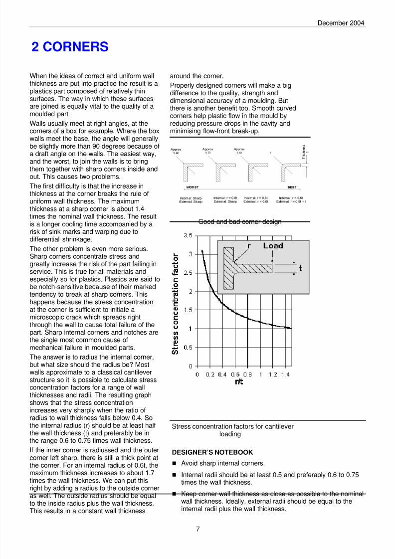
Walls usually meet at right angles, at thecorners of a box for example. Where the boxwalls meet the base, the angle will generallybe slightly more than 90 degrees because ofa draft angle on the walls. The easiest way,and the worst, to join the walls is to bringthem together with sharp corners inside andout. This causes two problems.
The first difficulty is that the increase in
thickness at the corner breaks the rule ofuniform wall thickness. The maximumthickness at a sharp corner is about 1.4times the nominal wall thickness. The resultis a longer cooling time accompanied by arisk of sink marks and warping due todifferential shrinkage.
The other problem is even more serious.Sharp corners concentrate stress andgreatly increase the risk of the part failing inservice. This is true for all materials andespecially so for plastics. Plastics are said tobe notch-sensitive because of their marked
tendency to break at sharp corners. Thishappens because the stress concentrationat the corner is sufficient to initiate amicroscopic crack which spreads rightthrough the wall to cause total failure of thepart. Sharp internal corners and notches arethe single most common cause ofmechanical failure in moulded parts.
The answer is to radius the internal corner,but what size should the radius be? Mostwalls approximate to a classical cantileverstructure so it is possible to calculate stressconcentration factors for a range of wallthicknesses and radii. The resulting graphshows that the stress concentrationincreases very sharply when the ratio ofradius to wall thickness falls below 0.4. Sothe internal radius (r) should be at least halfthe wall thickness (t) and preferably be inthe range 0.6 to 0.75 times wall thickness.
If the inner corner is radiussed and the outercorner left sharp, there is still a thick point atthe corner. For an internal radius of 0.6t, themaximum thickness increases to about 1.7times the wall thickness. We can put this
right by adding a radius to the outside corneras well. The outside radius should be equalto the inside radius plus the wall thickness.This results in a constant wall thickness
around the corner.
Properly designed corners will make a bigdifference to the quality, strength anddimensional accuracy of a moulding. Butthere is another benefit too. Smooth curvedcorners help plastic flow in the mould byreducing pressure drops in the cavity andminimising flow-front break-up.
2 CORNERS
Good and bad corner design
DESIGNER’S NOTEBOOK
n Avoid sharp internal corners.
n Internal radii should be at least 0.5 and preferably 0.6 to 0.75times the wall thickness.
n Keep corner wall thickness as close as possible to the nominalwall thickness. Ideally, external radii should be equal to theinternal radii plus the wall thickness.
Stress concentration factors for cantileverloading
7
8/8/2019 Design Plastics
http://slidepdf.com/reader/full/design-plastics 11/30
December 2004
8
So far in this design series we have seenthat plastics parts should be made withrelatively thin and uniform walls linked by
corner radii, not sharp corners. Both ideasare important in the design of ribs.
When the normal wall thickness is not stiffenough or strong enough to stand up toservice conditions the part should bestrengthened by adding ribs rather thanmaking the whole wall thicker. The principleis the familiar one used in steel girderswhere 'I' and 'T' sections are almost as rigidas solid beams but are only a fraction of theweight and cost.
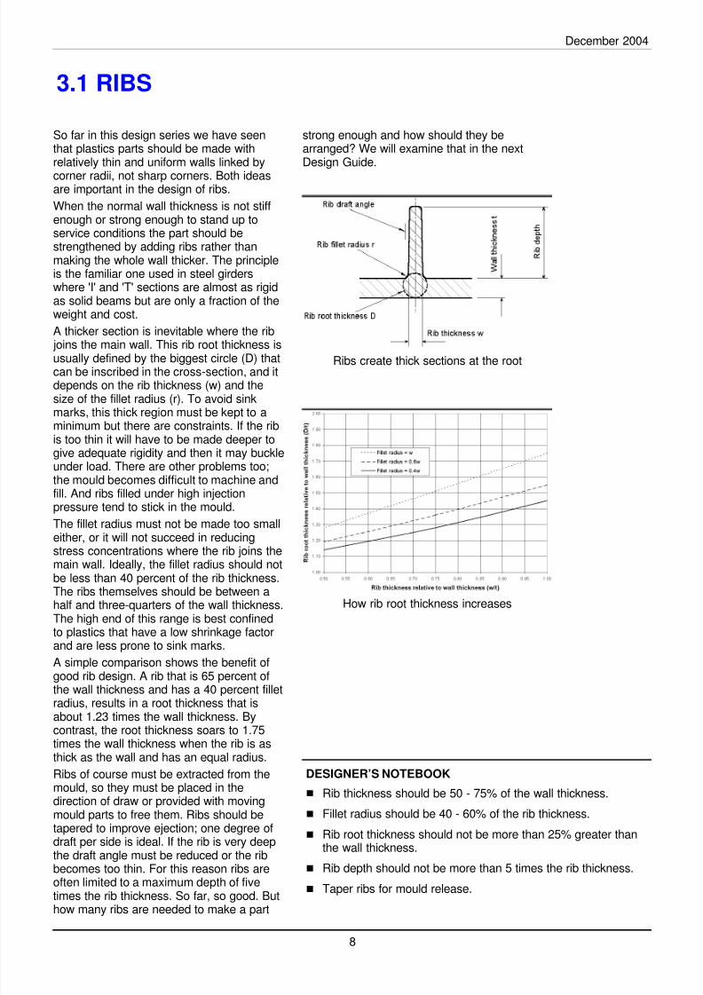
A thicker section is inevitable where the rib
joins the main wall. This rib root thickness isusually defined by the biggest circle (D) thatcan be inscribed in the cross-section, and itdepends on the rib thickness (w) and thesize of the fillet radius (r). To avoid sinkmarks, this thick region must be kept to aminimum but there are constraints. If the ribis too thin it will have to be made deeper togive adequate rigidity and then it may buckleunder load. There are other problems too;the mould becomes difficult to machine andfill. And ribs filled under high injectionpressure tend to stick in the mould.
The fillet radius must not be made too smalleither, or it will not succeed in reducingstress concentrations where the rib joins themain wall. Ideally, the fillet radius should notbe less than 40 percent of the rib thickness.The ribs themselves should be between ahalf and three-quarters of the wall thickness.The high end of this range is best confinedto plastics that have a low shrinkage factorand are less prone to sink marks.
A simple comparison shows the benefit ofgood rib design. A rib that is 65 percent ofthe wall thickness and has a 40 percent filletradius, results in a root thickness that isabout 1.23 times the wall thickness. Bycontrast, the root thickness soars to 1.75times the wall thickness when the rib is asthick as the wall and has an equal radius.
Ribs of course must be extracted from themould, so they must be placed in thedirection of draw or provided with movingmould parts to free them. Ribs should betapered to improve ejection; one degree ofdraft per side is ideal. If the rib is very deepthe draft angle must be reduced or the rib
becomes too thin. For this reason ribs areoften limited to a maximum depth of fivetimes the rib thickness. So far, so good. Buthow many ribs are needed to make a part
strong enough and how should they bearranged? We will examine that in the nextDesign Guide.
3.1 RIBS
Ribs create thick sections at the root
DESIGNER’S NOTEBOOK
n Rib thickness should be 50 - 75% of the wall thickness.
n Fillet radius should be 40 - 60% of the rib thickness.
n Rib root thickness should not be more than 25% greater thanthe wall thickness.
nRib depth should not be more than 5 times the rib thickness.
n Taper ribs for mould release.
How rib root thickness increases
8/8/2019 Design Plastics
http://slidepdf.com/reader/full/design-plastics 12/30
December 2004
Cross-ribbed plate calculator Source: DuPont
Terms for the calculator
Alternative rib junctions
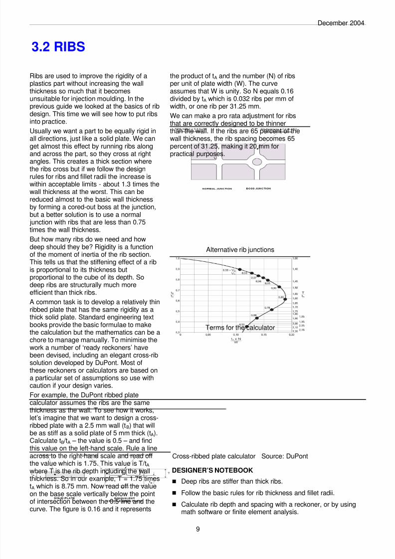
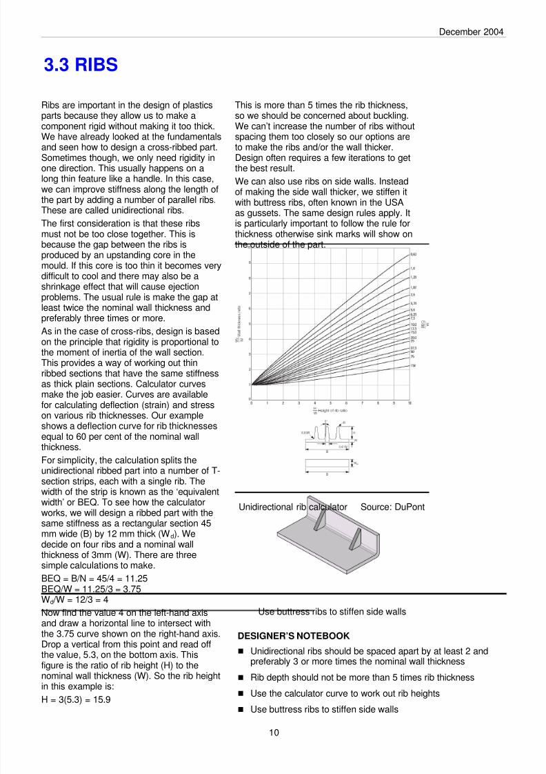
Ribs are used to improve the rigidity of aplastics part without increasing the wallthickness so much that it becomes
unsuitable for injection moulding. In theprevious guide we looked at the basics of ribdesign. This time we will see how to put ribsinto practice.
Usually we want a part to be equally rigid inall directions, just like a solid plate. We canget almost this effect by running ribs alongand across the part, so they cross at rightangles. This creates a thick section wherethe ribs cross but if we follow the designrules for ribs and fillet radii the increase iswithin acceptable limits - about 1.3 times thewall thickness at the worst. This can bereduced almost to the basic wall thicknessby forming a cored-out boss at the junction,but a better solution is to use a normal junction with ribs that are less than 0.75times the wall thickness.
But how many ribs do we need and howdeep should they be? Rigidity is a functionof the moment of inertia of the rib section.This tells us that the stiffening effect of a ribis proportional to its thickness butproportional to the cube of its depth. Sodeep ribs are structurally much more
efficient than thick ribs.A common task is to develop a relatively thinribbed plate that has the same rigidity as athick solid plate. Standard engineering textbooks provide the basic formulae to makethe calculation but the mathematics can be achore to manage manually. To minimise thework a number of ‘ready reckoners’ havebeen devised, including an elegant cross-ribsolution developed by DuPont. Most ofthese reckoners or calculators are based ona particular set of assumptions so use withcaution if your design varies.
For example, the DuPont ribbed platecalculator assumes the ribs are the samethickness as the wall. To see how it works,let’s imagine that we want to design a cross-ribbed plate with a 2.5 mm wall (tB) that willbe as stiff as a solid plate of 5 mm thick (tA).Calculate tB /tA – the value is 0.5 – and findthis value on the left-hand scale. Rule a lineacross to the right-hand scale and read offthe value which is 1.75. This value is T/tA where T is the rib depth including the wallthickness. So in our example, T = 1.75 times
tA which is 8.75 mm. Now read off the valueon the base scale vertically below the pointof intersection between the 0.5 line and thecurve. The figure is 0.16 and it represents
the product of tA and the number (N) of ribsper unit of plate width (W). The curveassumes that W is unity. So N equals 0.16
divided by tA which is 0.032 ribs per mm ofwidth, or one rib per 31.25 mm.
We can make a pro rata adjustment for ribsthat are correctly designed to be thinnerthan the wall. If the ribs are 65 percent of thewall thickness, the rib spacing becomes 65percent of 31.25, making it 20 mm forpractical purposes.
3.2 RIBS
9
DESIGNER’S NOTEBOOK
n Deep ribs are stiffer than thick ribs.
n Follow the basic rules for rib thickness and fillet radii.
n Calculate rib depth and spacing with a reckoner, or by usingmath software or finite element analysis.
8/8/2019 Design Plastics
http://slidepdf.com/reader/full/design-plastics 13/30

8/8/2019 Design Plastics
http://slidepdf.com/reader/full/design-plastics 14/30
December 2004
The boss is one of the basic designelements of a plastics moulding. Bosses areusually cylindrical because that is the
easiest form to machine in the mould and itis also the strongest shape to have in themoulded part. The boss is used wheneverwe need a mounting point, a location point,a reinforcement around a hole, or a spacer.The boss may receive an insert, a screw, ora plain shaft either as a slide or a press fit.In other words, the boss is not as simple asit looks. Depending on its use, it may haveto stand up to a whole combination offorces – tension, compression, torsion,flexing, shear and bursting - so it must bedesigned accordingly.
We can start with some general designrules, using the principles we have alreadydeveloped for ribs and walls. The boss canbe thought of as a special case of a rib; onethat is wrapped round in the form of a tube.An 'ideal' boss, designed according to ribrules, would not produce sink marks or stickin the mould but unfortunately the tubularform of the boss would not be strong enoughin most cases. In real life, most bossesbreak some rib design rules by necessity.This means that boss design is a
compromise between sink marks andfunctionality.
Rigidity is the simplest aspect of bossdesign. This can be achieved by supportingthe boss with buttress ribs, and often bylinking the boss to a side wall. The supportribs can be designed to normal rib rules sothat sink marks and stress points areavoided.
When the boss is linked to a side wall, eitherat an edge or the corner of a component,there is a right and a wrong way to do it. Thewrong way is simply to extend the boss
outside diameter to meet the wall. Thisinevitably produces a thick section that willresult in sink marks, voids, and long coolingcycles. The right way is to link or tie the bossto the side wall with a flat rib, preferablyrecessed a little below the boss or edgeheight so that it cannot interfere with anyassembly conditions. The other ribs that tiethe boss to the base wall remain as buttressribs. For economical machining of themould, the ribs should be aligned on the X-Yaxes of the component except for the flatcorner rib which is placed at 45 degrees.
The single diagonal rib is better than two X-Y ribs because it avoids a small mould corebetween the ribs. Such small cores are
prone to damage and are difficult to cool;this may result in slower moulding cyclesand more down time.
So we have established how to connect theboss to the rest of the component. The moredifficult part of boss design concerns thehole and the thickness of the boss.
4.1 BOSSES
11
Boss design is a compromise
DESIGNER’S NOTEBOOK
n Before designing a boss, consider its function and the forcesacting on it during assembly and service
n If the forces are not great, it may be possible to dispense withsupport ribs, otherwise:
n Anchor the boss to the base wall with buttress ribs.
n If possible, anchor the boss to the side wall with aflat rib.
n Avoid rib arrangements that result in small mouldcores or complicated mould machining set-ups.
There is a right and a wrong way to supportbosses

8/8/2019 Design Plastics
http://slidepdf.com/reader/full/design-plastics 15/30
December 2004
Perhaps the most common function of aboss is to accept a screw fastener. Thereare two types of screw in widespread use.
Thread-cutting screws work by cutting awaypart of the boss inner wall as they are drivenin. This produces a female thread, and someswarf. Thread-forming screws produce thefemale thread by a cold flow process; theplastic is locally deformed rather than cutand there is no swarf. Generally, thread-forming screws are preferred forthermoplastics whereas thread-cuttingscrews are better for hard inelastic materialssuch as thermosets. The range of screws onthe market makes it difficult to give a generaldesign rule, but one approach is to use the
flexural modulus of the material as a guideto which type to use.
Screw bosses must be dimensioned towithstand both screw insertion forces andthe load placed on the screw in service. Thesize of the hole relative to the screw iscritical for resistance to thread stripping andscrew pull-out, while the boss diameter mustbe large enough to withstand hoop stressesinduced by the thread forming process.Screw bosses have one important additionalfeature: the screw hole is provided with a
counterbore. This reduces stress at theopen end of the boss and helps to prevent itsplitting. The counterbore also provides ameans of locating the screw prior to driving.
The dimensions of the boss and holedepend on two things; the screw threaddiameter and the plastics material type. Thetable gives boss, hole and depth factors fora variety of plastics. To design a screwboss, look up the material and multiply thescrew thread diameter by the appropriatefactors to dimension the hole, boss andminimum thread engagement depth. Once
again, the variety of available screw typesand plastics grades means that generalguidelines must be used with caution.
Screw and boss performance can also beadversely affected by outside influences. Ifthe boss has been moulded with a weld line,the burst strength may be reduced. A lotdepends on service conditions too: if theboss is exposed to a high servicetemperature, or to environmental stresscracking agents, its performance will bereduced, sometimes drastically.
When designing bosses for screws, use themanufacturer's recommendations for theparticular screw type but for criticalapplications, there is no substitute for testingbefore finalising the design.
12
4.2 BOSSES
Flexural Modulus of plastic (Mpa) Preferred screw typeLess than 1,400 Thread-forming1,400 to 2,800 Thread-forming or Thread-cutting
2,800 to 6,900 Thread-cutting
Greater than 6,900 Thread-cutting, fine pitch
Screw boss design factors Sources: TR Fastenings and ASP
Screw selection depends on material Source: DuPont
Material Hole Factor Boss Factor Depth FactorABS 0.80 2.00 2.0
ABS/PC 0.80 2.00 2.0
ASA 0.78 2.00 2.0PA 46 0.73 1.85 1.8
PA 46 GF 30% 0.78 1.85 1.8
PA 6 0.75 1.85 1.7
PA 6 GF 30% 0.80 2.00 1.9
PA 66 0.75 1.85 1.7
PA 66 GF 30% 0.82 2.00 1.8PBT 0.75 1.85 1.7
PBT GF 30% 0.80 1.80 1.7
PC 0.85 2.50 2.2PC GF 30% 0.85 2.20 2.0
PE-HD 0.75 1.80 1.8
PE-LD 0.75 1.80 1.8
PET 0.75 1.85 1.7
PET GF 30% 0.80 1.80 1.7
PMMA 0.85 2.00 2.0
POM 0.75 1.95 2.0PP 0.70 2.00 2.0
PP TF 20% 0.72 2.00 2.0
PPO 0.85 2.50 2.2PS 0.80 2.00 2.0
PVC-U 0.80 2.00 2.0
SAN 0.77 2.00 1.9
Boss dimensions are a function of material and screw diameter
DESIGNER’S NOTEBOOK
n Select the right screw type - thread-forming or thread-cutting -to suit the plastics material.
n Use a counterbore to reduce stress at the open end.
n Make the hole deep enough to prevent screw bottoming.
n Use the manufacturer's design recommendation, otherwiseuse the factors in this design guide as a starting point.
n Test, if the application is critical.
8/8/2019 Design Plastics
http://slidepdf.com/reader/full/design-plastics 16/30
December 2004
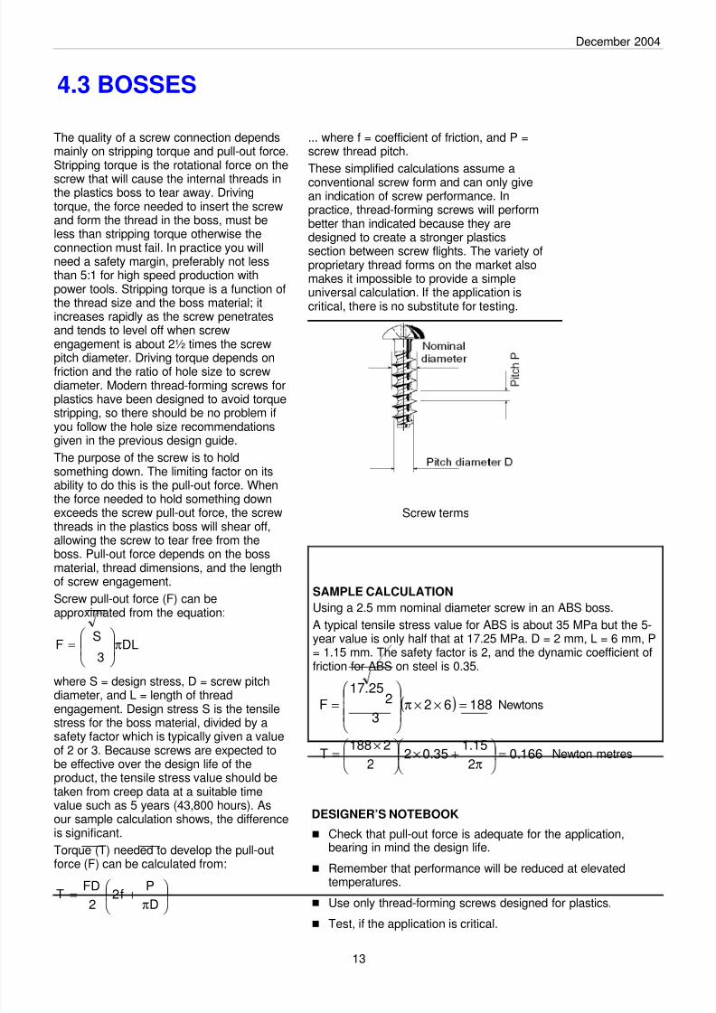
The quality of a screw connection dependsmainly on stripping torque and pull-out force.Stripping torque is the rotational force on the
screw that will cause the internal threads inthe plastics boss to tear away. Drivingtorque, the force needed to insert the screwand form the thread in the boss, must beless than stripping torque otherwise theconnection must fail. In practice you willneed a safety margin, preferably not lessthan 5:1 for high speed production withpower tools. Stripping torque is a function ofthe thread size and the boss material; itincreases rapidly as the screw penetratesand tends to level off when screwengagement is about 2½ times the screw
pitch diameter. Driving torque depends onfriction and the ratio of hole size to screwdiameter. Modern thread-forming screws forplastics have been designed to avoid torquestripping, so there should be no problem ifyou follow the hole size recommendationsgiven in the previous design guide.
The purpose of the screw is to holdsomething down. The limiting factor on itsability to do this is the pull-out force. Whenthe force needed to hold something downexceeds the screw pull-out force, the screw
threads in the plastics boss will shear off,allowing the screw to tear free from theboss. Pull-out force depends on the bossmaterial, thread dimensions, and the lengthof screw engagement.
Screw pull-out force (F) can beapproximated from the equation:
where S = design stress, D = screw pitchdiameter, and L = length of thread
engagement. Design stress S is the tensilestress for the boss material, divided by asafety factor which is typically given a valueof 2 or 3. Because screws are expected tobe effective over the design life of theproduct, the tensile stress value should betaken from creep data at a suitable timevalue such as 5 years (43,800 hours). Asour sample calculation shows, the differenceis significant.
Torque (T) needed to develop the pull-outforce (F) can be calculated from:
... where f = coefficient of friction, and P =screw thread pitch.
These simplified calculations assume aconventional screw form and can only givean indication of screw performance. Inpractice, thread-forming screws will performbetter than indicated because they aredesigned to create a stronger plasticssection between screw flights. The variety ofproprietary thread forms on the market alsomakes it impossible to provide a simpleuniversal calculation. If the application iscritical, there is no substitute for testing.
4.3 BOSSES
13
Screw terms
DL3
SF π
=
π+=
DPf2
2FDT
SAMPLE CALCULATION
Using a 2.5 mm nominal diameter screw in an ABS boss.
A typical tensile stress value for ABS is about 35 MPa but the 5-year value is only half that at 17.25 MPa. D = 2 mm, L = 6 mm, P= 1.15 mm. The safety factor is 2, and the dynamic coefficient offriction for ABS on steel is 0.35.
Newtons
Newton metres
( ) 188623
225.17
F =××π
=
166.02
15.135.02
2
2188T =
π
+×
×=
DESIGNER’S NOTEBOOK
n Check that pull-out force is adequate for the application,bearing in mind the design life.
n Remember that performance will be reduced at elevated
temperatures.n Use only thread-forming screws designed for plastics.
n Test, if the application is critical.

8/8/2019 Design Plastics
http://slidepdf.com/reader/full/design-plastics 17/30
December 2004
14
The bearing is a dynamic application ofplastics; one where there is relative motionbetween the plastics and another
component. Such bearings offer a number ofadvantages over the conventional type. Theplastics bearing is shock and wear resistant,light in weight, damps down running noiseand vibration, costs little, and requires littleor no lubrication and maintenance.
Plastics bearings can take the form ofplastics-to-plastics assemblies but the mostcommon design uses a steel shaft running ina plastics sleeve bearing. The bearing maybe machined or moulded, depending on theapplication and material. Some bearingmaterials, for example PTFE and UHMWPE,do not lend themselves to conventionalmoulding processes and so are usuallymachined. Moulding produces a bearingwith accurate dimensions and a fine surfacefinish without imposing any additionalcomponent costs, and so is much to bepreferred. The moulded bearing can take theform of a bush that is fitted into anothercomponent, or can be formed integrally inthe body of a moulding. This last solution isonly feasible when it is economically andmechanically practical to make an entire
component in the bearing material. Thetechnique of ‘outsert’ moulding is particularlyeffective when a number of bearings areneeded in a metal chassis or sub-assembly(see Part 19).
The performance of the bearing depends ona number of factors including temperature,running speed, bearing clearance, and theshaft characteristics. For steel shafts, theimportant characteristics are hardness andsurface finish, in that order. The shaft shouldbe as hard and smooth as possible; if theshaft is too soft, a very smooth surface will
not prevent bearing wear.The bearing capability can be calculatedfrom the operating pressure and velocity.The operating pressure (P) is given by:
where F = load on the bearing, L = bearinglength and D = shaft diameter.
The sliding velocity (V) is derived from:
where N = rotational speed of the shaft.
Bearing wear (W) is proportional tooperating pressure times sliding velocity,and is given by the expression:
7.1 BEARINGS
DESIGNER’S NOTEBOOK
n For metal shafts, the harder and smoother the better.
n Keep within the PV limit.
n Use specific grade data for K-factor and PV limit.
n Except for slow-running and lightly loaded bearings, verify thedesign by testing prototypes.
LD
FP =
DNV π=
Typical figures for PV limit and K-factor
Key bearing features
where K is a wear constant known as the K-
factor.The K-factor is a good guide to wearperformance but the factor does vary withthe PV value, so calculations should besupplemented by prototype testing. Alimiting value of PV is also used as a designparameter. The PV limit is the combinationof bearing pressure and velocity beyondwhich the bearing is no longer wearresistant. The table gives representativevalues for K-factor and PV limit for commonbearing materials. These values are forunmodified materials in contact with steel.
Many bearing materials include lubricatingand strengthening additives such asgraphite, PTFE, molybdenum disulphide andglass. These can make a significantdifference to the values, so obtain specificgrade data before making designcalculations.
Material Limiting PV
(MPa.m/min)
K-factor
10-13(cm3.min/m.kg.hr)Polyamide PA6 4.8 23.7
Polyamide PA6/10 4.8 21.3
Polyamide PA6/6 5.8 3.6
Polybutylene terephthalate 6.3 24.9Acetal 6.9 7.7
( )PV K W =

8/8/2019 Design Plastics
http://slidepdf.com/reader/full/design-plastics 18/30
December 2004
In the previous Design Guide we saw thatthe performance of a plastics bearingdepends on the PV limit and the K-factor of
the material. We gave typical values forcommon bearing materials but do bear inmind that PV and K values changesignificantly when lubricating and reinforcingadditives are included in the plasticscompound. For bearing design, you willneed to get the actual values for the gradeyou are using, or for a close equivalent.
The ratio of bearing length to shaft diameteraffects the generation of frictional heat in therunning assembly. When the length is greatcompared with the diameter, heat may buildup in the centre portion of the bearing.However, if the bearing is too short it beginsto fail in its function of guiding the shaft, andthere may also be retention problems if thebearing is of the press-in type. A good ruleof thumb is to use a ratio of 1:1. In otherwords, set the bearing length dimension tobe about the same as the shaft diameter. Ofcourse, if the shaft runs only slowly orintermittently, frictional heating is unlikely tobe a problem.
The next issue is to work out the wallthickness of the bearing. There are two
general considerations. If the bearing isoperating at a high PV value then heatingmay be a problem, so use a minimal wallthickness to help dissipate the heat.Conversely, if the assembly is likely to besubject to impact, use a thicker wall to resistshock. The graph gives a rough guide to asuitable bearing wall thickness for a range ofshaft sizes. The graph is for general purposebearing plastics in average circumstances.Remember that the strength of reinforcedbearing materials can be much greater thanthat of unmodified materials.
Plastics bearings need greater runningclearances than metal bearings, mainly dueto thermal expansion. If we assume that theoutside diameter of the bearing isconstrained then any expansion will result ina reduction of the bore. Thermal expansionwill occur if the bearing warms up whenrunning and will also take place if the servicetemperature is significantly above normalroom temperature. Other factors that canaffect the running clearance are mouldingtolerances and post-shrinkage, moistureabsorption in polyamide bearings, and the
compression effect when a separate bush ispress-fitted in a rigid bore. As a guide, thediametral clearance between an assembled
7.2 BEARINGS
15
DESIGNER’S NOTEBOOK
n Keep the ratio of bearing length to shaft diameter close to 1:1.
n Bearing wall thickness can normally be in the range 2 mm to 5mm for small to medium shaft diameters.
n Assembled diametral bearing clearances should not be lessthan 0.3% to 0.5% of shaft diameter.
n Consider whether the clearance needs to be increased toallow for temperature rises, moulding tolerances, post-shrinkage, moisture absorption, or press-fitting compression.
Bearing wall thickness as a function of shaftdiameter
shaft and bearing should be in the range0.3% to 0.5% of shaft diameter, and shouldnever be less than 0.3%.
The total clearance needed before assemblywill be this figure plus allowances for any ofthe other factors that apply. The temperatureeffect on the bearing wall thickness can becalculated by applying the coefficient ofthermal expansion for the plastic to thetemperature rise expected due to friction orthe environment, whichever is the greater.The maximum compression effect in apress-fitted bearing is simply the maximumbearing outside diameter minus theminimum diameter of the bore that it ispressed into.

8/8/2019 Design Plastics
http://slidepdf.com/reader/full/design-plastics 19/30
December 2004
Design problems
16
So far we have looked at the mechanicalfactors affecting the performance of plasticsbearings. These issues include PV limit, K-
factor, length-diameter ratio, andclearances. Now let’s see what effectphysical design can have on performance.Of course, the wide scope for designvariation means we must generalise. Theeffects we discuss will be more severe forhigher running speeds and loads. Wherebearings are slow running and lightly loadedthere is naturally much more design latitude.
The materials of the bearing and shaft canhave a big influence on wear. Soft metalssuch as mild steel and non-ferrous metalsdo not perform well as shafts in plasticsbearings. This is true even for plastics withfriction-reducing additives. The harder theshaft, the lower the wear. The shaft shouldalso have a good surface finish but even apolished surface will not overcome thedisadvantage of a shaft that is too soft.Some plastics-to-plastics combinationsresult in very low wear. The shaft hardnessgraph shows that an acetal/nylon pairing ismuch better than any acetal/metalcombination.
The graph also demonstrates that wear
begins gradually then accelerates rapidly.This happens when wear debris begins toact as a grinding medium. You can reducethe problem by providing somewhere for thedebris to go. The simplest way is to designthe bearing with grooves running in the axialdirection. The groove width can be about 10percent of shaft diameter and should bedeep enough to accommodate wearparticles with room to spare. Use at leastthree grooves, and more in a large diameterbearing. If the bearing wall would beweakened too much by grooves, you could
use a series of through holes as analternative. The holes should be staggeredso that they sweep the full surface of theshaft. Through holes of course have thedisadvantage that they are much moredifficult to produce in a moulded bearing.
Never forget the difference between theoryand practice. Calculations assume perfectlycylindrical bearings precisely aligned withthe shaft so that loads are evenlydistributed. This can be difficult to achieve,particularly when the bearing is an integralpart of a larger moulding. If the bearing is in
the form of an unsupported bush projectingfrom a moulding wall, there is a possibilitythat cantilever loads on the end of the
7.3 BEARINGS
DESIGNER’S NOTEBOOK n Plastics bearings work best with hard shafts.
n Grooved bearings last longer.
n Use at least three grooves.n Groove width should be 10 percent of shaft diameter.
n Support bearings adequately.
Hard metal shafts are better; plastics shaftsare best
Grooved bearings last longer
bearing or deflection in the supporting wallwill result in a slight misalignment. Thismeans that the bearing load will be unevenly
distributed and performance will suffer.Misalignment can be reduced or eliminatedby supporting the bearing bush with ribs.However, this raises the risk that shrinkagein the ribs will distort the bearing bore fromthe perfectly cylindrical form. In this case, itmay be necessary to mould the bearing boreundersize and machine out to the finalaccurate dimension.
8/8/2019 Design Plastics
http://slidepdf.com/reader/full/design-plastics 20/30
December 2004
Plastics gears have a number of advantagesover the traditional metal gears. They arelightweight, run quietly, are resistant to
corrosion, and operate with little or nolubrication. Perhaps the biggest benefitcomes from the injection moulding processthat makes it possible to produce a complexgear in a single rapid operation. The result ismuch cheaper than a machined metal gear.A moulded gear can also incorporate otherintegral features such as springs or cams;the metal equivalent would almost certainlybe an assembly of separate parts.
Of course, plastics have disadvantages too.The precision, load-carrying capacity, anddimensional stability of plastics gears aregenerally inferior to those of metals. Bothprecision and stability are particularlyaffected by injection moulding so bestpractice is needed in component and moulddesign, in mould manufacture, and inprocess optimisation and control.
The most commonly used plastics for gearsby far are polyamides (PA) and acetals(POM). They are not the only choicesthough. Thermoplastic polyurethane (TPU),polybutylene terephthalate (PBT), polyimide(PI), polyamideimide (PAI), coether-ester
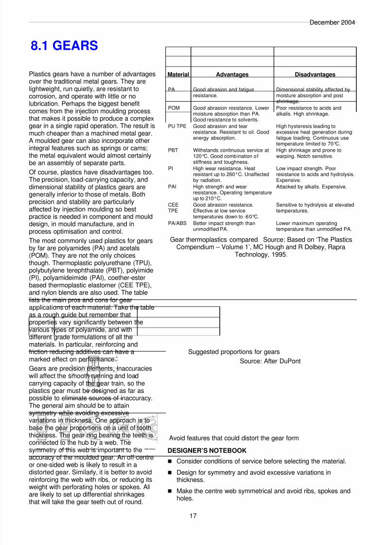
based thermoplastic elastomer (CEE TPE),and nylon blends are also used. The tablelists the main pros and cons for gearapplications of each material. Take the tableas a rough guide but remember thatproperties vary significantly between thevarious types of polyamide, and withdifferent grade formulations of all thematerials. In particular, reinforcing andfriction reducing additives can have amarked effect on performance.
Gears are precision elements. Inaccuracieswill affect the smooth running and load
carrying capacity of the gear train, so theplastics gear must be designed as far aspossible to eliminate sources of inaccuracy.The general aim should be to attainsymmetry while avoiding excessivevariations in thickness. One approach is tobase the gear proportions on a unit of tooththickness. The gear ring bearing the teeth isconnected to the hub by a web. Thesymmetry of this web is important to theaccuracy of the moulded gear. An off-centreor one-sided web is likely to result in adistorted gear. Similarly, it is better to avoid
reinforcing the web with ribs, or reducing itsweight with perforating holes or spokes. Allare likely to set up differential shrinkagesthat will take the gear teeth out of round.
8.1 GEARS
17
Material Advantages Disadvantages
PA Good abrasion and fatigue
resistance.
Dimensional stability affected by
moisture absorption and postshrinkage.
POM Good abrasion resistance. Lowermoisture absorption than PA.Good resistance to solvents.
Poor resistance to acids andalkalis. High shrinkage.
PU TPE Good abrasion and tearresistance. Resistant to oil. Goodenergy absorption.
High hysteresis leading toexcessive heat generation duringfatigue loading. Continuous usetemperature limited to 70°C.
PBT Withstands continuous service at120°C. Good combination ofstiffness and toughness.
High shrinkage and prone towarping. Notch sensitive.
PI High wear resistance. Heatresistant up to 260°C. Unaffectedby radiation.
Low impact strength. Poorresistance to acids and hydrolysis.Expensive.
PAI High strength and wear
resistance. Operating temperatureup to 210°C.
Attacked by alkalis. Expensive.
CEETPE
Good abrasion resistance.Effective at low servicetemperatures down to -60°C.
Sensitive to hydrolysis at elevatedtemperatures.
PA/ABS Better impact strength thanunmodified PA.
Lower maximum operatingtemperature than unmodified PA.
Gear thermoplastics compared Source: Based on ‘The PlasticsCompendium – Volume 1’, MC Hough and R Dolbey, Rapra
Technology, 1995.
Suggested proportions for gears
Source: After DuPont
Avoid features that could distort the gear form
DESIGNER’S NOTEBOOK
n Consider conditions of service before selecting the material.
n Design for symmetry and avoid excessive variations inthickness.
n Make the centre web symmetrical and avoid ribs, spokes andholes.
8/8/2019 Design Plastics
http://slidepdf.com/reader/full/design-plastics 21/30
December 2004
8.2 GEARS
Suggested proportions for gears
Source: After DuPont
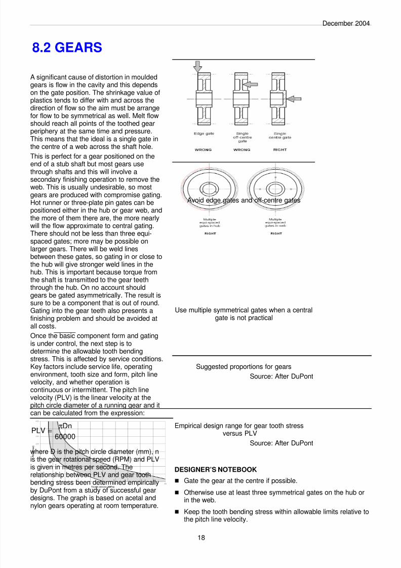
Avoid edge gates and off-centre gates
DESIGNER’S NOTEBOOK
n Gate the gear at the centre if possible.
n Otherwise use at least three symmetrical gates on the hub orin the web.
n Keep the tooth bending stress within allowable limits relative tothe pitch line velocity.
18
A significant cause of distortion in mouldedgears is flow in the cavity and this dependson the gate position. The shrinkage value of
plastics tends to differ with and across thedirection of flow so the aim must be arrangefor flow to be symmetrical as well. Melt flowshould reach all points of the toothed gearperiphery at the same time and pressure.This means that the ideal is a single gate inthe centre of a web across the shaft hole.
This is perfect for a gear positioned on theend of a stub shaft but most gears usethrough shafts and this will involve asecondary finishing operation to remove theweb. This is usually undesirable, so mostgears are produced with compromise gating.Hot runner or three-plate pin gates can bepositioned either in the hub or gear web, andthe more of them there are, the more nearlywill the flow approximate to central gating.There should not be less than three equi-spaced gates; more may be possible onlarger gears. There will be weld linesbetween these gates, so gating in or close tothe hub will give stronger weld lines in thehub. This is important because torque fromthe shaft is transmitted to the gear teeththrough the hub. On no account should
gears be gated asymmetrically. The result issure to be a component that is out of round.Gating into the gear teeth also presents afinishing problem and should be avoided atall costs.
Once the basic component form and gatingis under control, the next step is todetermine the allowable tooth bendingstress. This is affected by service conditions.Key factors include service life, operatingenvironment, tooth size and form, pitch linevelocity, and whether operation iscontinuous or intermittent. The pitch line
velocity (PLV) is the linear velocity at thepitch circle diameter of a running gear and itcan be calculated from the expression:
where D is the pitch circle diameter (mm), nis the gear rotational speed (RPM) and PLVis given in metres per second. Therelationship between PLV and gear toothbending stress been determined empiricallyby DuPont from a study of successful gear
designs. The graph is based on acetal andnylon gears operating at room temperature.
60000
DnPLV
π=
Empirical design range for gear tooth stressversus PLV
Source: After DuPont
Use multiple symmetrical gates when a centralgate is not practical
8/8/2019 Design Plastics
http://slidepdf.com/reader/full/design-plastics 22/30
December 2004
8.3 GEARS
19
The allowable gear tooth bending stressdepends on the PLV and the tooth size (ordiametral pitch) - see Section 8.2 - but it is
influenced by a number of external factors.Some of these are environmental andinclude dimensional changes due totemperature or humidity, the operatingenvironment itself, and the presence orabsence of lubrication. Lubrication may beexternal in the form of an oil or grease, orinternal by means of low-friction additives inthe plastics material used to form the gear.Service conditions, for example the materialof the meshing gear and whether running isintermittent or continuous, also have abearing on allowable gear tooth bending
stress. So too does the design life of theassembly. Clearly, a higher stress can betolerated over a shorter life.
The load (F) normal to the tooth at the pitchcircle diameter (D) is a function of the torque(T) transmitted through the shaft. For a spurgear:
We also need to know the gear module (M).If (n) is the number of teeth on the gear,
then:
Then the bending stress (S) on the tooth canworked out from:
where f is the face width of the tooth and Yis a tooth form factor.
The tooth form factor depends on the toothpressure angle and the number of teeth onthe gear. For a typical plastics spur gear, thevalue of Y is in the region of 0.6 and in thatcase, the equation for tooth bending stressbecomes:
If F is measured in Newtons, and the valuesof M and f are given in millimetres, then Swill be calculated in megaPascals (MPa).This value of S is the actual tooth bendingstress. We now need to adjust the figure to
take account of fatigue, temperature, andshock loads.
The adjustment for fatigue is based on thefatigue strength at one million (106) cycles.
D
T2F =
n
DM =
MfY
FS =
Mf
F7.1S =
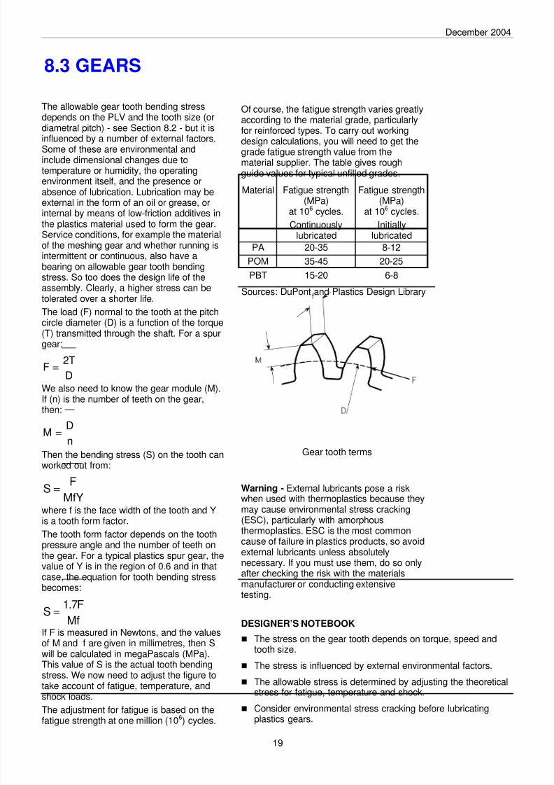
Of course, the fatigue strength varies greatlyaccording to the material grade, particularlyfor reinforced types. To carry out workingdesign calculations, you will need to get thegrade fatigue strength value from thematerial supplier. The table gives roughguide values for typical unfilled grades.
Warning - External lubricants pose a riskwhen used with thermoplastics because theymay cause environmental stress cracking(ESC), particularly with amorphousthermoplastics. ESC is the most commoncause of failure in plastics products, so avoid
external lubricants unless absolutelynecessary. If you must use them, do so onlyafter checking the risk with the materialsmanufacturer or conducting extensivetesting.
Material Fatigue strength(MPa)
at 106 cycles.
Continuouslylubricated
Fatigue strength(MPa)
at 106 cycles.
Initiallylubricated
PA 20-35 8-12
POM 35-45 20-25
PBT 15-20 6-8
Sources: DuPont and Plastics Design Library
Gear tooth terms
DESIGNER’S NOTEBOOK
n The stress on the gear tooth depends on torque, speed andtooth size.
n The stress is influenced by external environmental factors.
n The allowable stress is determined by adjusting the theoreticalstress for fatigue, temperature and shock.
n Consider environmental stress cracking before lubricatingplastics gears.
8/8/2019 Design Plastics
http://slidepdf.com/reader/full/design-plastics 23/30
December 2004
So for our example:
So the sustainable load is 18.35 Newtons.The conditions experienced by loadedrunning gears are complex and calculationsalone will not guarantee success. What theywill do is ensure that the design is in thearea of feasibility. If the gear runs in criticalapplications, or at high speeds or loads, orat elevated temperatures, you should testprototypes to prove the design.
8.4 GEARS
20
The theoretical tooth bending stress (S) mustlie within the limit for the material. This limit isnot the theoretical strength value but a lower
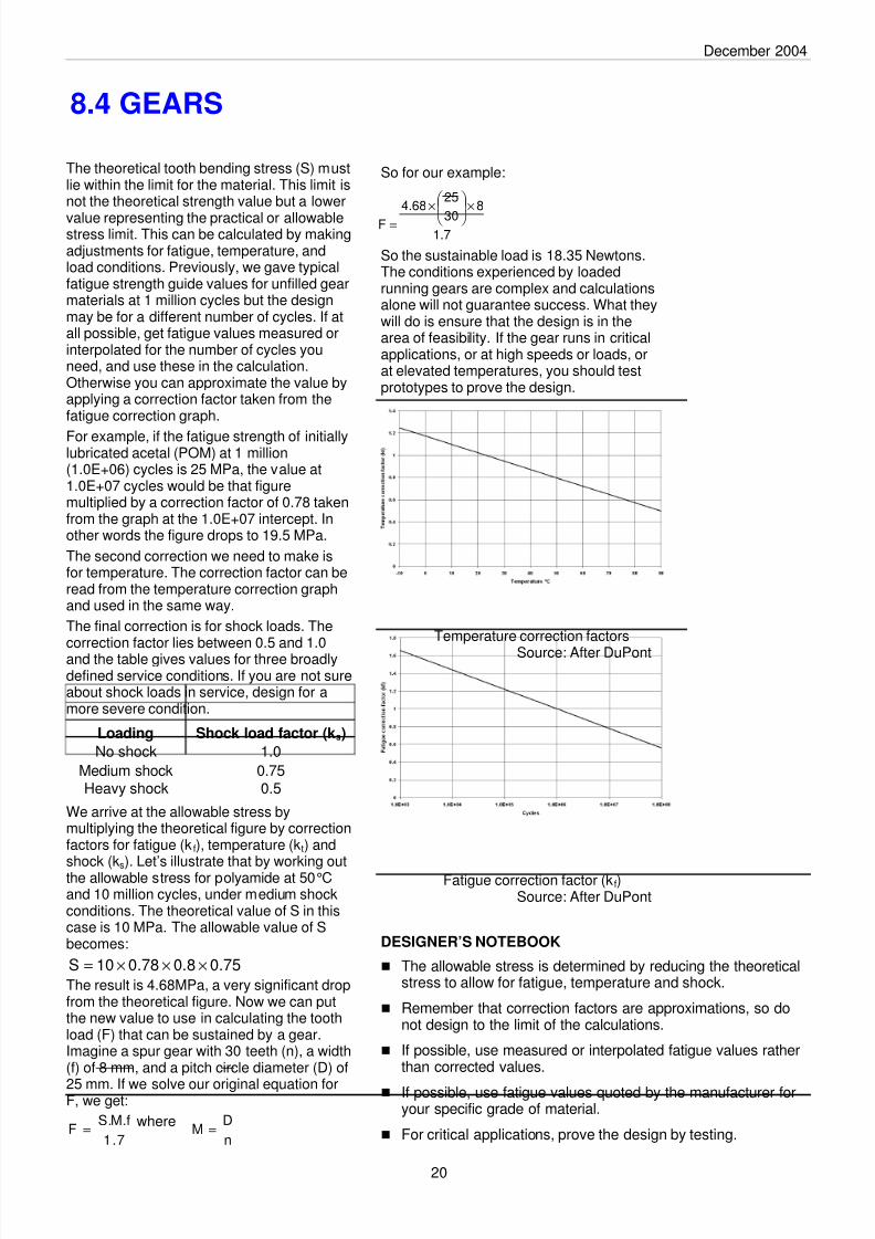
value representing the practical or allowablestress limit. This can be calculated by makingadjustments for fatigue, temperature, andload conditions. Previously, we gave typicalfatigue strength guide values for unfilled gearmaterials at 1 million cycles but the designmay be for a different number of cycles. If atall possible, get fatigue values measured orinterpolated for the number of cycles youneed, and use these in the calculation.Otherwise you can approximate the value byapplying a correction factor taken from thefatigue correction graph.
For example, if the fatigue strength of initiallylubricated acetal (POM) at 1 million(1.0E+06) cycles is 25 MPa, the value at1.0E+07 cycles would be that figuremultiplied by a correction factor of 0.78 takenfrom the graph at the 1.0E+07 intercept. Inother words the figure drops to 19.5 MPa.
The second correction we need to make isfor temperature. The correction factor can beread from the temperature correction graphand used in the same way.
The final correction is for shock loads. Thecorrection factor lies between 0.5 and 1.0and the table gives values for three broadlydefined service conditions. If you are not sureabout shock loads in service, design for amore severe condition.
We arrive at the allowable stress bymultiplying the theoretical figure by correctionfactors for fatigue (kf), temperature (kt) and
shock (ks). Let’s illustrate that by working outthe allowable stress for polyamide at 50°Cand 10 million cycles, under medium shockconditions. The theoretical value of S in thiscase is 10 MPa. The allowable value of Sbecomes:
The result is 4.68MPa, a very significant dropfrom the theoretical figure. Now we can putthe new value to use in calculating the toothload (F) that can be sustained by a gear.Imagine a spur gear with 30 teeth (n), a width(f) of 8 mm, and a pitch circle diameter (D) of
25 mm. If we solve our original equation forF, we get:
where
Loading Shock load factor (ks)
No shock 1.0
Medium shock 0.75Heavy shock 0.5
75.08.078.010S ×××=
7.1
f.M.SF =
n
DM =
7.1
8
30
2568.4
F
×
×=
Temperature correction factors
Source: After DuPont
Fatigue correction factor (kf)Source: After DuPont
DESIGNER’S NOTEBOOK
n The allowable stress is determined by reducing the theoreticalstress to allow for fatigue, temperature and shock.
n Remember that correction factors are approximations, so donot design to the limit of the calculations.
n If possible, use measured or interpolated fatigue values ratherthan corrected values.
n If possible, use fatigue values quoted by the manufacturer foryour specific grade of material.
n For critical applications, prove the design by testing.
8/8/2019 Design Plastics
http://slidepdf.com/reader/full/design-plastics 24/30
December 2004
8.5 GEARS
Gears work in pairs to transmit torque fromone axis or shaft to another. Spur or helicalgears are used when the shafts are parallel
and this is perhaps the most familiararrangement but not the only one. When theshafts intersect, motion can be transmittedthrough bevel gears. Shafts that are neitherparallel nor intersecting can be connectedby hypoid gears, crossed helical gears or bya worm and worm gear.
The worm and worm gear is useful when alarge speed ratio is needed, and has theunusual property of transmitting motion inone direction only, from worm to worm gear.But there is a major drawback. Spur, helicaland bevel gears operate in rolling motion butthe worm and worm gear work togetheralmost entirely in sliding contact. This ismechanically less efficient and requires adifferent design approach.
The sliding motion creates more friction andwear, and generates more heat from thetransmission of mechanical energy.Consequently, moulded worms and wormwheels should be made from gradescontaining low-friction or lubricatingadditives. Low wear characteristics are alsoimportant. External lubrication may be
needed too but first ensure that the lubricantis not a stress-cracking agent for the plastic.
It is best to pair different materials for theworm and worm gear. You can usedissimilar plastics or a combination ofplastics and metal. If frictional heat is aproblem, dissipation can be much improvedby using a metallic worm running with aplastics worm wheel. The table outlinessome common material pairings.
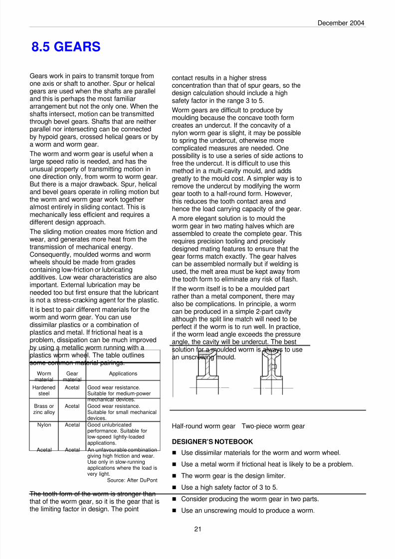
The tooth form of the worm is stronger thanthat of the worm gear, so it is the gear that isthe limiting factor in design. The point
Half-round worm gear Two-piece worm gear
DESIGNER’S NOTEBOOK
n Use dissimilar materials for the worm and worm wheel.
n Use a metal worm if frictional heat is likely to be a problem.
n The worm gear is the design limiter.
n
Use a high safety factor of 3 to 5.n Consider producing the worm gear in two parts.
n Use an unscrewing mould to produce a worm.
Wormmaterial
Gearmaterial
Applications
Hardened
steel
Acetal Good wear resistance.
Suitable for medium-powermechanical devices.
Brass orzinc alloy
Acetal Good wear resistance.Suitable for small mechanicaldevices.
Nylon Acetal Good unlubricatedperformance. Suitable forlow-speed lightly-loadedapplications.
Acetal Acetal An unfavourable combinationgiving high friction and wear.Use only in slow-runningapplications where the load isvery light.
Source: After DuPont
21
contact results in a higher stressconcentration than that of spur gears, so thedesign calculation should include a highsafety factor in the range 3 to 5.
Worm gears are difficult to produce bymoulding because the concave tooth formcreates an undercut. If the concavity of anylon worm gear is slight, it may be possibleto spring the undercut, otherwise morecomplicated measures are needed. Onepossibility is to use a series of side actions tofree the undercut. It is difficult to use thismethod in a multi-cavity mould, and addsgreatly to the mould cost. A simpler way is toremove the undercut by modifying the worm
gear tooth to a half-round form. However,this reduces the tooth contact area andhence the load carrying capacity of the gear.
A more elegant solution is to mould theworm gear in two mating halves which areassembled to create the complete gear. Thisrequires precision tooling and preciselydesigned mating features to ensure that thegear forms match exactly. The gear halvescan be assembled normally but if welding isused, the melt area must be kept away fromthe tooth form to eliminate any risk of flash.
If the worm itself is to be a moulded partrather than a metal component, there mayalso be complications. In principle, a wormcan be produced in a simple 2-part cavityalthough the split line match will need to beperfect if the worm is to run well. In practice,if the worm lead angle exceeds the pressureangle, the cavity will be undercut. The bestsolution for a moulded worm is always to usean unscrewing mould.

8/8/2019 Design Plastics
http://slidepdf.com/reader/full/design-plastics 25/30
8/8/2019 Design Plastics
http://slidepdf.com/reader/full/design-plastics 26/30
December 2004
23
In Design Guide 4, we looked at bossesused with thread-forming screws as ameans of joining or assembling plastics
parts. There are many other ways ofachieving the same object, for example bywelding, adhesives, staking and snap-fits.But of all these methods, the snap-fit isperhaps the most elegant way of joiningplastics parts together.
Snap-fits involve pushing a projection onone part past an obstruction on a matingpart. They rely entirely for their effect on theelasticity of plastics. Generally, one part ismore or less rigid while the other part isflexible or resilient. Depending on thedesign, the joint can be permanent orreleasable. Both parts can be plastics -either the same or different types, or onepart can be a foreign material such as ametal shaft or a laminated circuit board.
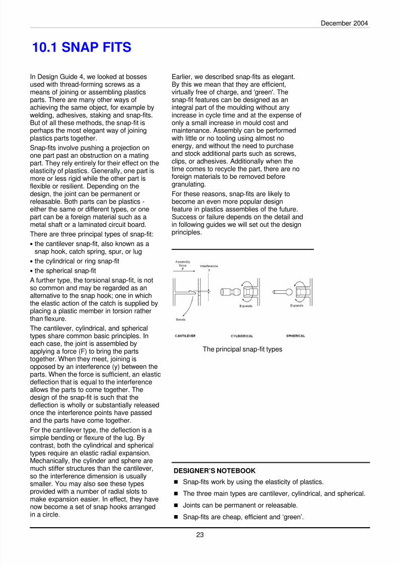
There are three principal types of snap-fit:
• the cantilever snap-fit, also known as asnap hook, catch spring, spur, or lug
• the cylindrical or ring snap-fit
• the spherical snap-fit
A further type, the torsional snap-fit, is notso common and may be regarded as an
alternative to the snap hook; one in whichthe elastic action of the catch is supplied byplacing a plastic member in torsion ratherthan flexure.
The cantilever, cylindrical, and sphericaltypes share common basic principles. Ineach case, the joint is assembled byapplying a force (F) to bring the partstogether. When they meet, joining isopposed by an interference (y) between theparts. When the force is sufficient, an elasticdeflection that is equal to the interferenceallows the parts to come together. The
design of the snap-fit is such that thedeflection is wholly or substantially releasedonce the interference points have passedand the parts have come together.
For the cantilever type, the deflection is asimple bending or flexure of the lug. Bycontrast, both the cylindrical and sphericaltypes require an elastic radial expansion.Mechanically, the cylinder and sphere aremuch stiffer structures than the cantilever,so the interference dimension is usuallysmaller. You may also see these types
provided with a number of radial slots tomake expansion easier. In effect, they havenow become a set of snap hooks arrangedin a circle.
Earlier, we described snap-fits as elegant.By this we mean that they are efficient,virtually free of charge, and 'green'. The
snap-fit features can be designed as anintegral part of the moulding without anyincrease in cycle time and at the expense ofonly a small increase in mould cost andmaintenance. Assembly can be performedwith little or no tooling using almost noenergy, and without the need to purchaseand stock additional parts such as screws,clips, or adhesives. Additionally when thetime comes to recycle the part, there are noforeign materials to be removed beforegranulating.
For these reasons, snap-fits are likely tobecome an even more popular designfeature in plastics assemblies of the future.Success or failure depends on the detail andin following guides we will set out the designprinciples.
10.1 SNAP FITS
DESIGNER’S NOTEBOOK
n Snap-fits work by using the elasticity of plastics.
n The three main types are cantilever, cylindrical, and spherical.n Joints can be permanent or releasable.
n Snap-fits are cheap, efficient and ‘green’.
The principal snap-fit types

8/8/2019 Design Plastics
http://slidepdf.com/reader/full/design-plastics 27/30
December 2004
24
In the previous design guide, we looked atthe general principles of snap-fits. Now let'sexamine the most popular type - the
cantilever or hook - in more detail. Thecantilever type clicks or snaps intoengagement when it is pushed past a catchon a mating part. The hook has a taperedface with a shallow engagement angle tohelp it past the obstruction. A releasablesnap hook has a second tapered face set ata release angle to allow it to be removedagain. The release angle is greater than theengagement angle, to make releaserelatively difficult. If release is too easy, thesnap-fit will not act as a reliable fastener.When the release angle approaches 90
degrees, removal by pulling is virtuallyimpossible and the snap-fit becomes apermanent joint.
When the cantilever hook is pushed past thecatch, it is forced to flex. The amount ofdeflection is equal to the interferencebetween hook and catch, and this must bekept to a dimension that does not exceedthe allowable strain for the cantilevermaterial. The table shows approximatedesign data for a range of unfilled materials.The allowable strain figures are for a snap-fit
that is used just a few times. If it is to beused once only, the strain figures can bedoubled. The figures in the table should betaken as a guide only. For accurate design,you will need to get grade-specific figuresfrom your materials supplier.
For a snap hook with a constant crosssection, the maximum deflection Y can beworked out from this equation:
The equation assumes that only the snaphook flexes. In many cases, the mouldingface that it is attached to will also flex a little.This can be regarded as a safety factor. Ifthe hook mounting is rigid, then you shouldreduce the calculated maximum deflectionby a safety factor.
The normal force P needed to move thesnap hook through deflection y comes fromthis equation:
This result can be used to work out the forceW needed to engage the snap fit with thecatch.
In the case of a releasable snap hook, thesame formula can be used to work out therelease force by substituting the releaseangle b for the engagement angle a. If therelease force approaches the tensilestrength of the snap hook, then it is likely tobreak as you try to release it. Similarly, thecatch will shear off if its cross-section is tooweak compared with either the engagementforce or release force. Of course, if the snaphook is properly designed, the release forcewill always be the greater, even in areleasable design.
10.2 SNAP FITS
DESIGNER’S NOTEBOOK
n Keep within the allowable strain figure.
n If the calculated allowable deflection is too small, tryincreasing the snap hook length.
n Design so that the snap hook is no longer flexed after it hasclicked into the catch
n Snap-fits are meant to be used either once or just a few times,so fatigue and wear can be neglected.
n Radius the root of the snap hook to reduce stressconcentration.
t5.1
ely
2
=
l6
EewtP
2
=
atan1
atanPW
µ−+µ
=
Material Allowable strain(e) (%)
Flexural modulus(E) (Gpa)
Coefficient offriction (ì )
PS 2 3.0 0.3
ABS 2 2.1 0.2
SAN 2 3.6 0.3
PMMA 2 2.9 0.4
LDPE 5 0.2 0.3
HDPE 4 1.2 0.3
PP 4 1.3 0.3PA 3 1.2 0.1
POM 4 2.6 0.4PC 2 2.8 0.4
Snap-fit dimensions and forces

8/8/2019 Design Plastics
http://slidepdf.com/reader/full/design-plastics 28/30
December 2004
25
The cylindrical or ring snap-fit has acontinuous internal undercut that is engagedby a groove on a shaft. It is often used to
retain a plastics part such as a knob on ametal shaft but it can also be used to securetwo plastics parts together. Like other snapfits the joint can be designed to bereleasable or permanent depending on theslope of the release angle. When the joint isinserted or released, the hub is forced toexpand elastically. This makes for a springthat is inherently stiffer and stronger than thecantilever hook type of snap fit. Strength isusually an advantage but there are somedrawbacks too. The insertion force can bequite high and it is often necessary to make
the undercut relatively small. The hub worksbest when it is moulded in a comparativelyelastic material, not least because it must beejected off an undercut core in the mould.This means that stiff glass-filled and otherreinforced grades may not be suitable forthe ring snap fit.
The stiffness of the hub spring depends notonly on its thickness but also on its freelength and crucially on how close theundercut is to the free end. Ring snap fitsshould always be designed with the
undercut reasonably near the hub free end,otherwise the stiffness of the spring willsignificantly greater and the joint may fail.
Assembly of the joint is made easier byproviding a draft or engagement angle onthe end of the shaft . An angle of 20° to 30°works well. The release angle determineshow easily the snap fit can be disengaged.The greater the angle, the harder it is torelease. An angle of 40° to 50° is usual. Usea greater angle if you want the joint to bepermanent.
The diagram shows the key features for a
cylindrical snap-fit. The maximum allowableundercut can be worked out from thisequation:
where S = design stress, v = Poisson’s ratio,E = Modulus of elasticity and K = geometryfactor.
The geometry factor K can be calculated by:
The table gives approximate values forPoisson’s ratio for a range of unfilledmaterials. For accurate design, you will need
to get grade figures from your materialssupplier.
The expansion force exerted on the hub isgiven by the equation:
where µ = coefficient of friction and Sy =stress due to interference. Values for thecoefficient of friction were listed in theprevious Design Guide.
10.3 SNAP FITS
DESIGNER’S NOTEBOOK
n Don’t use cylindrical snap-fits with very stiff materials.
n Use an engagement angle of 20° to 30° and a release angle
of 40° to 50°. n Place the undercut near the open end of the hub.
n Size the undercut so that the design stress figure is notexceeded.
Main features of cylindrical snap-fits
−+
+=
shaft
shaft
hub
hub
E
v1
E
vK
K
Sdy
2
2
D
d1
D
d
1K
−
+=
[ ]
K
dlSatanP
y πµ+=
Material Poisson’s ratiov
PS 0.38
PMMA 0.40
LDPE 0.49
HDPE 0.47
PP 0.43
PA 0.45
PC 0.42PVC 0.42
PPO 0.41
PPS 0.42
Steel 0.28
8/8/2019 Design Plastics
http://slidepdf.com/reader/full/design-plastics 29/30
December 2004
26
And now, by applying the principle of levers,we can work out the opening force W thus:
where b = length of opening lever.
So by making b relatively large compared toa , we can arrange for the opening force tobe quite small. Be careful how you do thisthough. If a is made too small, the angle oftwist x becomes too great.
10.4 SNAP FITS
DESIGNER’S NOTEBOOK
n Use torsion snap-fits when you want to be able to release thecatch easily.
n Include a design feature to show where to press.
n Design a stop feature to prevent excessive torsion.
n Do not make the catch lever length too short otherwise thetwist angle and torsion becomes too great.
n Reduce the opening force by making the length of the openinglever longer than the catch lever.
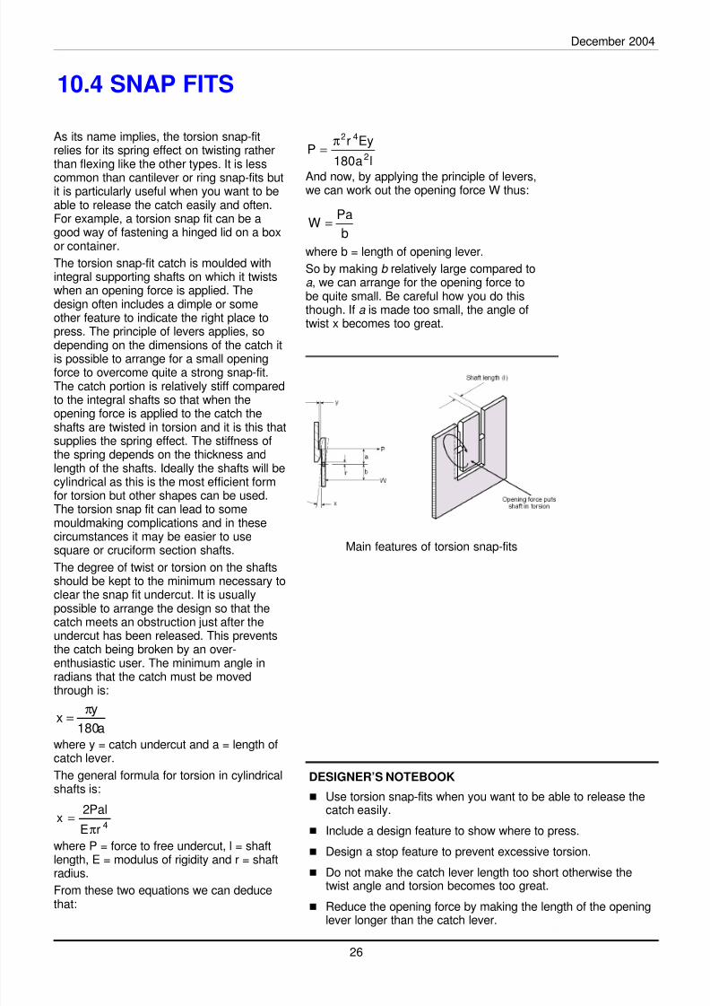
As its name implies, the torsion snap-fitrelies for its spring effect on twisting ratherthan flexing like the other types. It is less
common than cantilever or ring snap-fits butit is particularly useful when you want to beable to release the catch easily and often.For example, a torsion snap fit can be agood way of fastening a hinged lid on a boxor container.
The torsion snap-fit catch is moulded withintegral supporting shafts on which it twistswhen an opening force is applied. Thedesign often includes a dimple or someother feature to indicate the right place topress. The principle of levers applies, sodepending on the dimensions of the catch itis possible to arrange for a small openingforce to overcome quite a strong snap-fit.The catch portion is relatively stiff comparedto the integral shafts so that when theopening force is applied to the catch theshafts are twisted in torsion and it is this thatsupplies the spring effect. The stiffness ofthe spring depends on the thickness andlength of the shafts. Ideally the shafts will becylindrical as this is the most efficient formfor torsion but other shapes can be used.The torsion snap fit can lead to some
mouldmaking complications and in thesecircumstances it may be easier to usesquare or cruciform section shafts.
The degree of twist or torsion on the shaftsshould be kept to the minimum necessary toclear the snap fit undercut. It is usuallypossible to arrange the design so that thecatch meets an obstruction just after theundercut has been released. This preventsthe catch being broken by an over-enthusiastic user. The minimum angle inradians that the catch must be movedthrough is:
where y = catch undercut and a = length ofcatch lever.
The general formula for torsion in cylindricalshafts is:
where P = force to free undercut, l = shaftlength, E = modulus of rigidity and r = shaftradius.
From these two equations we can deducethat:
a180
yx π=
4rE
Pal2x
π=
la180
EyrP
2
42π=
b
PaW =
Main features of torsion snap-fits
8/8/2019 Design Plastics
http://slidepdf.com/reader/full/design-plastics 30/30
About the pdg: The Plastics Design Group (PDG) is a group of plastics expertswho share a common enthusiasm for the encouragement of the sound design of plasticsproducts irrespective of the manufacturing methods employed.
The objectives of the PDG are:
• To encourage sound plastics product design with particular reference to sustainability.
• To develop and produce resources for designers in the plastics and associatedindustries.
• To further the promotion and development of the Pentamode Code of Practice.
Membership of the PDG is open to anyone with an interest in promoting good design practice in plastics.
The PDG is a sub-group of the Plastics Consultancy Network, a professional network of the best independentplastics consultants in the world. PCN members are independent, highly qualified and experienced plasticsconsultant with a proven track record in plastics consultancy and years of experience in industry.
For further details of PDG or PCN Membership, contact:
Dr Robin KentPlastics Consultancy Networkc/o Tangram Technology Ltd.
PO BOX 24HITCHIN, SG5 2FP
Tel: 08700 278 379, Fax: 08700 278 493, e-mail: [email protected]
About Econology: Econology is a plastics industry information service
company, with particular expertise in communications and software. Thebedrock of the business is a long record of industrial experience andachievement but what makes the company effective is a mastery of informationsources and technology. Our strength is knowing where to find and how to use facts and figures, buyers andsellers, media and markets, technology and training, processes and people.
Econology is directed by Clive Maier, a plastics industry professional and a Fellow of the Institute of Materials
Minerals & Mining. He writes regularly for leading plastics industry journals circulating in the UK, Europe, andSouth East Asia. Other publications include a major volume on polypropylene and a number of other books andindustry reports.
For further details about Econology, contact:
Clive MaierEconology Ltd.4 Norsted Lane, Pratts BottomORPINGTON, BR6 7PGTel: 01689 860 686, Fax: 01689 860 686, email: [email protected]
About the British Plastics Federation: The British Plastics
Federation (BPF) is the leading trade association of the UK Plastics Industry(representing approximately 80% of turnover), a springboard for industry action,
existing to exploit common opportunities and resolve shared problems.Membership encompasses polymer producers, suppliers and processors in addition to additive and machinerysuppliers and manufacturers.
The BPF is an authoritative, well-respected and objective source of unique information, views and commentarywhose name has, as a consequence, become synonymous with plastics in the UK. The BPF promotes theinterests of its Members principally through its four Market Sector Groups and its many common interest BusinessGroups. The BPF Central Expert Committees address industry wide concerns including Environment, Fire,Product Safety and Industrial Health & Safety.
For further details of BPF Membership, contact:
Iain McIlweeBusiness Services ManagerThe British Plastics Federation
6 Bath Place, Rivington StreetLondon, EC2A 3JE
Tel: 020 7457 5000 Fax: 020 7457 5045 e-mail: imcilwee@bpf co uk
pdgplastics design group


![[TECH]Honeywell Plastics Design Solutions Guide](https://img.dokumen.tips/doc/110x75/5695d2d21a28ab9b029bd6bc/techhoneywell-plastics-design-solutions-guide.jpg)


![[Harold Belofsky] Plastics Product Design and Proc](https://img.dokumen.tips/doc/110x75/563db836550346aa9a91947d/harold-belofsky-plastics-product-design-and-proc.jpg)