Embed Size (px)
Citation preview

Design Patterns for Checkpoint-Based RollbackRecovery ∗
Titos Saridakis
NOKIA Research Center
PO Box 407, FIN-00045, [email protected]
Abstract
Checkpoint-based rollback recovery is a very popular category of fault toler-ance techniques, which are based on a simple idea: save the system state duringerror-free portions of the system execution; when an error occurs, use the savedstate to rollback the system to a recent consistent state. This way, after an erroroccurs the system does not have to start its execution from the beginning, whichwould result in longer execution times or even failure of the system (e.g. whenthe I/O events that drove the execution of the system are not reproducible). Thispaper presents three design patterns that capture the most widely used methodsfor checkpoint-based rollback recovery. The Independent Checkpoint pattern de-scribes the method where constituent components of a system take checkpointswithout synchronizing with each other. Synchronization will take place after theoccurrence of an error when a consistent system state must be re-established fromthe partial system states found in the checkpoints. The Coordinated Checkpointpattern describes the method where constituent components of a system take check-points after synchronizing with each other. In this case, no synchronization is re-quired during the re-establishment of a consistent system state after the occurrenceof an error. Finally, the Communication-Induced Checkpoint pattern describesthe methods where the synchronization of the checkpointing is triggered by com-munication events. This method combines the benefits of the previous two in termsof time and space overhead incurred to the system execution.
1 Introduction
Rollback recovery has been one of the most widely used means for system recovery inthe occurrence of errors. The basic idea behind it is to model the system execution as asuccession of system states and, when an error occurs while the system is reaching somestate, to roll the system back to a previously reached state and resume execution from thatstate. In order to be able to do this, the system saves in stable storage some of the statesit reaches during its execution. The saved states are called checkpoints and the actionis called checkpointing or taking a checkpoint. The system recovery techniques that are
∗Copyright 2003 c© by NOKIA. All rights reserved. Permission is granted to copy for PLoP 2003.

based on taking checkpoints and, after an error is detected, restoring a legitimate systemstate from the checkpoints previously taken, are qualified as checkpoint-based rollbackrecovery.
The general idea behind checkpoint-based rollback recovery techniques is simple. How-ever, elaborating the way this simple general idea can be applied in distributed systemsbrings forward a number of issues that complicate its application in distributed systems.A witness to the complexity of checkpoint-based rollback recovery techniques is a varietyof obscure checkpoint algorithms that have been reported in the related literature. Suchalgorithms describe ways to synchronize the constituent components of a system whentaking checkpoints (e.g. see [19]) and ways to reconstitute a consistent global state fromcheckpoints that contain partial representations of system states (e.g. see [22] and [13]).Two broad classifications of the checkpoint techniques are those that categorize themaccording to the software layer which is responsible for taking checkpoints, and thosethat categorize them according to synchronization of constituent components of a systemduring the checkpointing.
Software layer responsible for checkpointing. Assuming the common separationof the software in OS, middleware and application layers, one issue that checkpoint-basedrollback recovery techniques have to address is the layer responsible for taking checkpoints.Taking checkpoints at the OS layer provides transparency of the checkpoint mechanism tothe middleware and application layers (e.g. see [3] and [11]). This means that by puttingin place the checkpoint mechanism once for a given OS, the middleware and all applica-tions running on that OS can take advantage of it without necessitating and modification.On the other hand, deducing when middleware and applications are in a meaningful statethat can checkpointed requires a substantial effort at the OS level. This category of check-point techniques is called transparent checkpoints. As an alternative to this approach, theapplication software can be responsible for taking checkpoints (e.g. see [5] and [20]). Al-though this solves the problem of identifying meaningful application states that can becheckpoint, it also implies that the checkpoint mechanism is application specific. Thus,all applications that need checkpoint-based rollback recovery have to be modified to inte-grate the checkpoint mechanism. This category of checkpoint techniques is called explicitcheckpoints. Taking checkpoints at the middleware level (e.g. see [1]) attempts to combinethe benefits of the previous two approaches while minimizing the compromises; applica-tions are not modified as long as they run on top of the middleware that provides thecheckpoint mechanism while, being close to the application layer, it is easier to iden-tify meaningful application states at the middleware level. This category of checkpointtechniques is called implicit checkpoints. This category also includes compiler-assistedcheckpoint insertion (e.g. see [16] and [15]).
Checkpointing synchronization. In explicit checkpoint, the application has the re-sponsibility to trigger checkpoints. In implicit and transparent checkpoint however, wherecheckpoints are triggered by middleware or OS, some logic must be implemented to triggerthe timing of checkpoints. One category of checkpoint timing techniques are those thatcoordinates all constituent components of a system when taking checkpoints (e.g. see [4]).The set of checkpoints taken after such coordination is guaranteed to form a consistentglobal state of the system for the cost of system-wide coordination. This category ofcheckpoint techniques is called coordinated checkpoints. Another category of checkpoint

timing techniques are those where constituent components of a system take their check-points without synchronizing with each other (e.g. [23]). The price to pay for the easinessof checkpointing is the need to find a subset of all taken checkpoints that constitutes aconsistent global state of the system. This category of checkpoint techniques is calledindependent checkpoints. Finally, hybrid checkpoints techniques attempt to use commu-nication events to trigger the checkpoints in order to combine the benefits of the twoaforementioned techniques (e.g. see [12]). This category of checkpoint techniques is calledcommunication-induced checkpoints.
In this paper, we describe three design patterns for checkpoint-based rollback recovery,which capture the three categories of checkpointing synchronization mentioned above. InSection 2 we provide some background definitions, including the system model and thenecessary fault tolerance concepts. Then, the Independent Checkpoint, CoordinatedCheckpoint, and Communication-Induced Checkpoint are presented in Sections 3, 4,and 5 respectively. The paper concludes with a summary of the presented patterns and adiscussion on the factors that can lead to the selection of one of them over the others.
2 Background
2.1 System Model
A system is an entity with a well-defined behavior in terms of output it produces andwhich is a function of the input it receives, the system logic and the passage of timeas observed by the system’s internal clock. By “well-defined behavior” that the outputproduced by the system is previously agreed upon and unambiguously distinguishablefrom output that does not qualify as well-defined behavior. The well-defined behaviorof a system is called the system specification. A system interacts with its environmentby receiving input from it and delivering output to it. A system can be decomposedinto constituent (sub)systems, often called system components, each component being asystem of its own. As such, it interacts with its environment (i.e. other components ofthe bigger system) by receiving input and delivering output to it, and it can be furtherdecomposed into its constituent (sub)systems.
A system is modeled as a state machine, where states contain the data that thesystem holds and operates on. A state transition is triggered by the system’s logic, orby the reception of input from the environment, or by the delivery of output to theenvironment. Hence, state transitions model the I/O operations of a system. Whena system is decomposed into its constituent components, each component is assigned aportion of the data the system operates on. The system decomposition may produce newstate transitions that capture the I/O operations between the constituent components.The reception of input is a non-deterministic event for a given system, i.e. a system cannotknow beforehand when input will be delivered and what the contents of the input willbe. However, for a given input and a given state in which the system receives this input,the execution of the system (i.e. states and state transition including these capturingoutput delivery) until the reception of the next input is deterministic. Hence, the systemexecution can be modeled as a sequence of deterministic state intervals, each starting bya non-deterministic event. We also assume that the system has the capacity to detectand capture sufficient information related to non-deterministic events e.g. in order toregenerate/replay them. Thus, the system execution follows the piecewise deterministic
(PWD) assumption [22].When decomposing a system into its constituent components, the communication
between the components is not instantaneous, i.e. an output produced by one componentmay take a measurable time before it is delivered to the component that is supposed toreceive it. A communication event, after the output is produced by a component A andbefore the corresponding input is delivered to the intended recipient component B, is partof the state of the communication channel between the components A and B.
2.2 Basic Fault Tolerance Concepts
A failure is said to occur in a system when the system’s environment observes an outputfrom the system that does not conform to its specification. An error is the part of thesystem, e.g. one of the system components, which is liable to lead to a failure. A fault isthe adjudged cause of an error and may itself be the result of a failure. Hence, a faultcauses an error that produces a failure, which subsequently may result to a fault, and soon [14]. Let us consider the following example:
A software bug in an application is a fault that leads to an error when theapplication execution reaches the point affected by the bug. This causes theapplication crash, which is a failure. By crashing, the application leavesblocked the socket ports it used, which is a fault. The computer on whichthe application crashed has socket ports that are not used by any process butstill not accessible to running applications, which is an error. This, in turn,leads to a failure when another application requests these ports.
Faults may occur either in the state of a component or in the state of a communicationchannel. The resulting errors can be arbitrary modification of state data, loss of state data,and loss or delays of the events in the communication channels. The consequences of theseerrors can be a variety of failures ranging from byzantine failures (arbitrary or maliciousdeviation from the system specification), to send- and receive-omission failures (losses ofcommunication events), and crash failures (components or communication channels ceaseexecuting).
The term unit of failure is used to denote a part of a system that fails independentlyfrom other parts of the system. In the system model presented before, the boundaries ofunits of failures usually coincide with component boundaries. But it is also possible tomap more than one components to a single unit of failure. In the latter case, if an erroroccurs in one of the components that belong to the same unit of failure, all the othercomponents in the same unit of failure will be considered to have failed. In practice,the unit of failure sets the part of a system which is monitored by an error detectionmechanism for errors. In practice, the units of failure are mapped to processes, individualcomputers, or even complete subnetworks, depending on the scale and the purpose of theoverall system.
To take corrective actions and prevent system failures, errors must be detected firstand then an error masking, fault repair or system recovery mechanism can be employedto prevent the system from experiencing a failure [17]. The design patterns presented inthis paper describe fault tolerance techniques that fall in the category of system recovery.Error detection is not addressed in these patterns; rather, the described system recov-ery techniques assume that adequate error detection is in place and notifies the systemrecovery mechanism when errors are detected.
2.3 Rollback Recovery Concepts
A global state of a system is the aggregation of the states of its constituent componentsplus the states of the communication channels among its components. A global state isconsistent if the following two conditions hold true.
1. For every component B whose state reflects the delivery of an input with contentproduced by component A, the state of component A reflects the production of thecorresponding output.
2. For every component A whose state reflects the production of output intended forcomponent B and the state of component B does not reflect the delivery of thecorresponding input, the state of the communication channel between A and Bcontains a trace (event plus content) of the intended communication (also calledmessage in transit).
The fundamental goal of rollback recovery techniques is to re-establish a consistentglobal state after an occurred error has caused inconsistencies in the global system state.The consistent state re-established by a rollback recovery technique does not have to beone that has occurred in the system execution prior to the occurrence of the error. Itis sufficient that the re-established consistent state could have occurred in the systemexecution before the error occurred.
To accomplish their goal, rollback recovery technique rely on taking checkpoints andusing them after an error occurred to re-establish a consistent system state. During therecovery period, the checkpoints are used to reconstruct a consistent system state from thepartial system states saved in the checkpoints taken by the constituent components. Theset of the most recent checkpoints that belong to a consistent global state is called recoveryline [20]. Once a consistent state is reconstructed, the system execution is “rolled back”to that state. Hence, rollback recovery techniques consist of two main activities: takingcheckpoints and using them to reconstruct a consistent system state after the occurrenceof an error. As we will see in the following sections, simplifying one of the two activitiescomplicates the other.
3 Independent Checkpoint
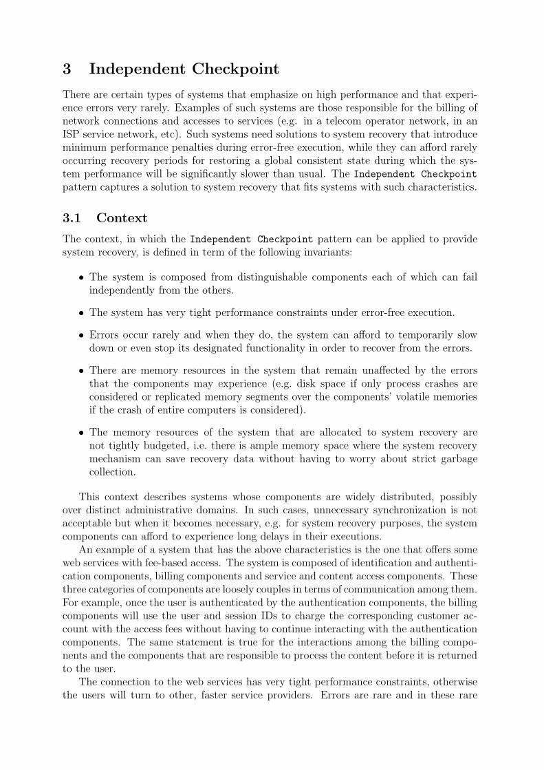
There are certain types of systems that emphasize on high performance and that experi-ence errors very rarely. Examples of such systems are those responsible for the billing ofnetwork connections and accesses to services (e.g. in a telecom operator network, in anISP service network, etc). Such systems need solutions to system recovery that introduceminimum performance penalties during error-free execution, while they can afford rarelyoccurring recovery periods for restoring a global consistent state during which the sys-tem performance will be significantly slower than usual. The Independent Checkpoint
pattern captures a solution to system recovery that fits systems with such characteristics.
3.1 Context
The context, in which the Independent Checkpoint pattern can be applied to providesystem recovery, is defined in term of the following invariants:
• The system is composed from distinguishable components each of which can failindependently from the others.
• The system has very tight performance constraints under error-free execution.
• Errors occur rarely and when they do, the system can afford to temporarily slowdown or even stop its designated functionality in order to recover from the errors.
• There are memory resources in the system that remain unaffected by the errorsthat the components may experience (e.g. disk space if only process crashes areconsidered or replicated memory segments over the components’ volatile memoriesif the crash of entire computers is considered).
• The memory resources of the system that are allocated to system recovery arenot tightly budgeted, i.e. there is ample memory space where the system recoverymechanism can save recovery data without having to worry about strict garbagecollection.
This context describes systems whose components are widely distributed, possiblyover distinct administrative domains. In such cases, unnecessary synchronization is notacceptable but when it becomes necessary, e.g. for system recovery purposes, the systemcomponents can afford to experience long delays in their executions.
An example of a system that has the above characteristics is the one that offers someweb services with fee-based access. The system is composed of identification and authenti-cation components, billing components and service and content access components. Thesethree categories of components are loosely couples in terms of communication among them.For example, once the user is authenticated by the authentication components, the billingcomponents will use the user and session IDs to charge the corresponding customer ac-count with the access fees without having to continue interacting with the authenticationcomponents. The same statement is true for the interactions among the billing compo-nents and the components that are responsible to process the content before it is returnedto the user.
The connection to the web services has very tight performance constraints, otherwisethe users will turn to other, faster service providers. Errors are rare and in these rare

cases the service may appear unavailable to its users who will have to attempt to access itanew. Furthermore, the service provider can have file server dedicated to storing recoverydata, hence ample storage space is available to the system recovery mechanism. What isimportant is that, in case of an error, the system restores a consistent state that containscorrect billing data, otherwise either the service provider will lose money or users willcomplain for being billed for content they never accessed.
3.2 Problem
In the above context, the Independent Checkpoint pattern solves the problem of re-establishing a consistent system state after the occurrence of an error by balancing thefollowing forces:
• Components need to save recovery data during error-free execution, in order to beable to recover from an error that may occur.
• Storing of recovery data introduces performance penalties which depend on theaccess latency of the media used to store the recovery data.
• The more frequently recovery data are saved by all components the more likely isto recover the system to a state closer to the point of the execution where the erroroccurred.
• The more frequently recovery data are saved the higher the performance penalty onerror-free executions becomes.
• For each component, the identification of the recovery data that belong to a consis-tent global state has a high cost in terms of performance.
3.3 Solution
The Independent Checkpoint pattern suggest the following solution to the above prob-lem. Each individual component in a system to decides on its own when to take check-points (i.e. when to save recovery data), without synchronizing with the checkpointingactivity of other components. The lack of synchronization of the checkpointing activitiesof the individual components keeps low the performance penalty during error-free execu-tions. This solution trades the low performance penalty during error-free execution with ahigh cost of the recovery activity that is launched after an error has occurred. During thisactivity, the components stop their execution and the recovery mechanism inspects thecheckpoints taken by all components in the system in order to identify the recovery line.When the recovery line is identified, the recovery mechanism instructs each componentto rollback to its checkpoint present in the identified recovery line. Upon reception ofthis instruction, each component loads the indicated checkpoint form stable storage andresumes execution from that point on.
In order for the recovery process to be able to identify the checkpoints that belong tothe recovery line, each checkpoint must contain some information that relates this check-point to checkpoints previously taken by other components. The technique for recordingin the independently taken checkpoints the information that relates them to other takencheckpoints is reported in [2] and it is summarized in the following. Each component Ci
takes a sequence of checkpoints ki,0, ki,1, ... during its execution. When a component Cα,

after it has taken checkpoint kα,x, produces some output that is intended to be deliveredas input to component Cβ, it piggybacks in the corresponding message the information(α, x), i.e. the identity of the sender and the identity of the last checkpoint the senderhas taken before producing the output in question. Component Cβ will deliver the in-put that corresponds to the aforementioned communication after having taken checkpointkβ,y. When taking checkpoint kβ,y+1, component Cβ will also record the dependency ofthe state saved in that checkpoint to the checkpoint kα,x.
Based on this dependency information saved with the checkpoints, the recovery mech-anism can identify the recovery line following different algorithms (e.g. see [2] and [23]).The basic idea behind these algorithms is to create a dependency graph among indi-vidually taken checkpoints and deduce from this graph which checkpoints belong to therecovery line.
N.B.: The solution suggested by the Independent Checkpoint pattern to the systemrecovery problem does not address error detection issues. Design patterns that addressthe error detection and notification problem are studied elsewhere [21].
3.4 Structure
The solution to the problem of system recovery described by the Independent Checkpoint
pattern outlines the following entities:
• The recoverable process, which is the component that checkpoints its state duringerror-free execution in order to be able to use it and recover from errors that it mayexperience.
• The stable storage, which is the part of the system where checkpoints are saved andwhich is not subject to errors.
• The checkpointer, which is responsible for the checkpoint activity of the recoverableprocess. The checkpointer decides when to take a checkpoint and it is responsiblefor transferring the recovery data (i.e. the component state to be checkpointed) tothe stable storage.
• The error detector, which is responsible for detecting errors that may occur to therecoverable process and, when errors are detected, to notify the recovery manager(see below) about them.
• The recovery manager, which controls the recovery activity. This entity receives theerror notification produced by the error detector entity and issues a request to thesystem components to suspend their execution. Then, it inspects the checkpointsin stable storage and identifies the recovery line for the system. Finally, it informseach component in the system about which of its checkpoints the component mustreload before it resumes its execution.
The checkpointer entity is usually, thought not necessarily, mapped to the same unitof failure as the recoverable process. On the other hand, both the error detector and therecovery manager must be mapped to different units of failure than the one where therecoverable process is mapped. The reason for this is because they are both used afteran error has occurred on the recoverable process and if they belong to the same unit offailure as the latter then they will not be able to deliver their designated functionality.
The stable storage is a logical entity that does not have to map to a single componentnecessarily. Replicated, distributed memory can serve as stable storage. However, thesystem developer has to consider the potential time overhead of finding the distributedmemory segment where a given checkpoint is stored. On the other hand, when stablestorage is mapped to a single physical entity (e.g. hard disk or flash memory), the systemdeveloper has to consider the potential time overhead of the simultaneous access of thephysical media by all system components during recovery phases.
Similarly to the stable storage the recovery manager may or may not be a singlephysical entity (e.g. a new component in the system). If the system developer choosesto distribute it over several physical entities (e.g. one instance of the recovery managerrunning on each system component), he must consider the subsequent time overhead dueto the synchronization of the distributed instances. On the other hand, if the recoverymanager is mapped on a single physical entity then the system developer must also dealwith error that may occur on the recovery manager itself.
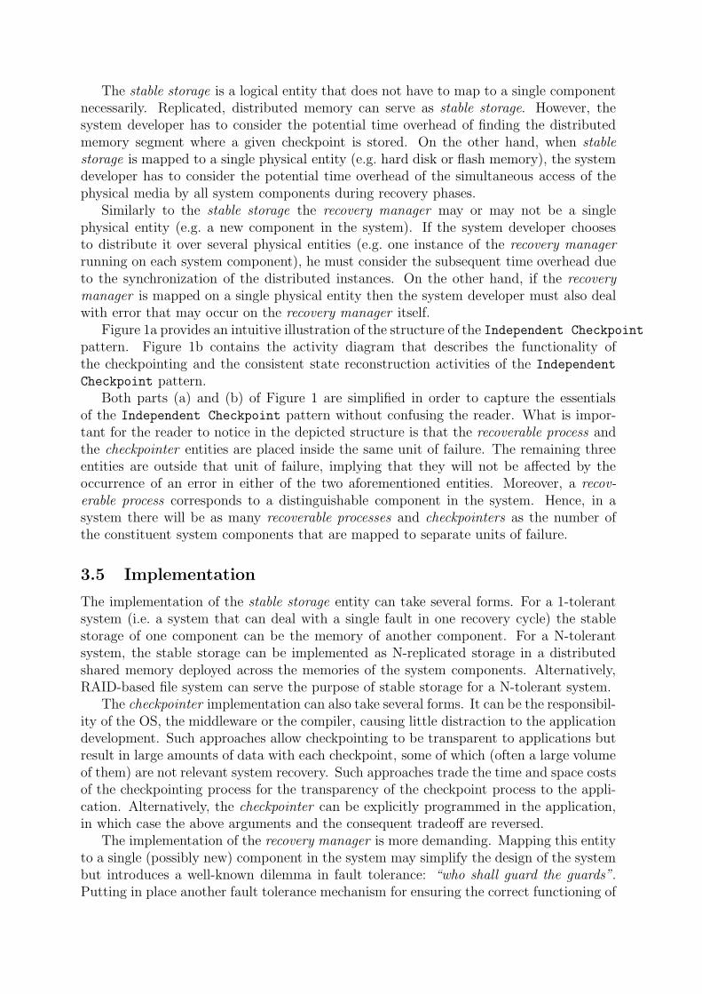
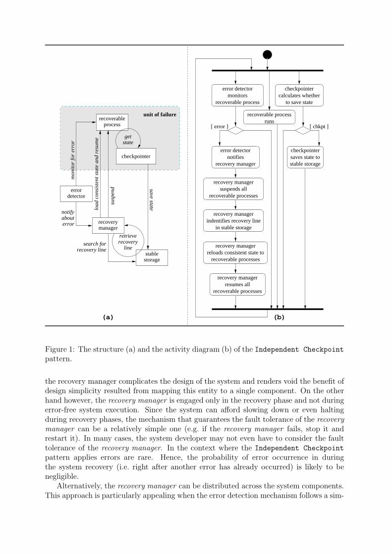
Figure 1a provides an intuitive illustration of the structure of the Independent Checkpoint
pattern. Figure 1b contains the activity diagram that describes the functionality ofthe checkpointing and the consistent state reconstruction activities of the Independent
Checkpoint pattern.Both parts (a) and (b) of Figure 1 are simplified in order to capture the essentials
of the Independent Checkpoint pattern without confusing the reader. What is impor-tant for the reader to notice in the depicted structure is that the recoverable process andthe checkpointer entities are placed inside the same unit of failure. The remaining threeentities are outside that unit of failure, implying that they will not be affected by theoccurrence of an error in either of the two aforementioned entities. Moreover, a recov-erable process corresponds to a distinguishable component in the system. Hence, in asystem there will be as many recoverable processes and checkpointers as the number ofthe constituent system components that are mapped to separate units of failure.
3.5 Implementation
The implementation of the stable storage entity can take several forms. For a 1-tolerantsystem (i.e. a system that can deal with a single fault in one recovery cycle) the stablestorage of one component can be the memory of another component. For a N-tolerantsystem, the stable storage can be implemented as N-replicated storage in a distributedshared memory deployed across the memories of the system components. Alternatively,RAID-based file system can serve the purpose of stable storage for a N-tolerant system.
The checkpointer implementation can also take several forms. It can be the responsibil-ity of the OS, the middleware or the compiler, causing little distraction to the applicationdevelopment. Such approaches allow checkpointing to be transparent to applications butresult in large amounts of data with each checkpoint, some of which (often a large volumeof them) are not relevant system recovery. Such approaches trade the time and space costsof the checkpointing process for the transparency of the checkpoint process to the appli-cation. Alternatively, the checkpointer can be explicitly programmed in the application,in which case the above arguments and the consequent tradeoff are reversed.
The implementation of the recovery manager is more demanding. Mapping this entityto a single (possibly new) component in the system may simplify the design of the systembut introduces a well-known dilemma in fault tolerance: “who shall guard the guards”.Putting in place another fault tolerance mechanism for ensuring the correct functioning of
retrieverecovery
line
[ error ] [ chkpt ]
notifyabouterror
mon
itor
for
erro
r
getstate
unit of failure
search forrecovery line
save state
susp
end
error detectormonitors
recoverable process
checkpointercalculates whether
to save state
recoverable processruns
checkpointersaves state tostable storage
error detectornotifies
recovery manager
recovery managersuspends all
recoverable processes
recovery manager
in stable storageindentifies recovery line
recovery managerresumes all
recoverable processes
recovery managerreloads consistent state to
recoverable processes
load
con
sist
ent s
tate
and
res
ume
(a) (b)
errordetector
processrecoverable
checkpointer
stablestorage
managerrecovery
Figure 1: The structure (a) and the activity diagram (b) of the Independent Checkpoint
pattern.
the recovery manager complicates the design of the system and renders void the benefit ofdesign simplicity resulted from mapping this entity to a single component. On the otherhand however, the recovery manager is engaged only in the recovery phase and not duringerror-free system execution. Since the system can afford slowing down or even haltingduring recovery phases, the mechanism that guarantees the fault tolerance of the recoverymanager can be a relatively simple one (e.g. if the recovery manager fails, stop it andrestart it). In many cases, the system developer may not even have to consider the faulttolerance of the recovery manager. In the context where the Independent Checkpoint
pattern applies errors are rare. Hence, the probability of error occurrence in duringthe system recovery (i.e. right after another error has already occurred) is likely to benegligible.
Alternatively, the recovery manager can be distributed across the system components.This approach is particularly appealing when the error detection mechanism follows a sim-

ilar distributed implementation approach (e.g. see error detection patterns in [21]). How-ever, such an approach implies that every component in the system can potentially playthe role of the recovery manager at a given moment. Hence the recovery manager func-tionality must be replicated across all system components resulting in an elevated spaceoverhead introduced by the implementation of the Independent Checkpoint pattern.
The implementation of the error detector depends on the error detection strategy thatit implements. In practice, the error detector may not be a single entity but rather a setof entities which cooperate to provide error detection and notification, as discussed in theerror detection pattern presented in [21].
3.6 Consequences
The Independent Checkpoint pattern has the following benefits:
+ The time overhead introduced to the error-free system execution is kept very low andequals the time needed to save independently taken checkpoints to stable storageplus the time to piggyback checkpoint information to the output produced by eachcomponent. Depending on the implementation choice for the checkpointer and theratio of the size of state data over the size of the executable image of a component,the performance penalty of the checkpointing activity can be fine-tuned to reach itsminimum.
+ The complexity of identifying consistent global states impacts on the system onlyafter an error has actually occurred, i.e. rarely, according to the context in whichthis pattern applies.
The Independent Checkpoint pattern imposes also some liabilities:
- The time overhead introduced to the system recovery activity is very high (thehighest for the three design patterns presented in this paper). This is due to thefact that after the occurrence of an error, the execution of the system componentsis suspended until the recovery manager calculates the dependency graphs of thecheckpoints in stable storage, identifies the recovery line, and informs each compo-nent about which checkpoint to load before resuming its execution.
- The lack of synchronization during the checkpoint activity of the components maycause the domino effect [20], i.e. the successive rollback of components from onecheckpoint to an older one until all of them reach their initial states. This extremerollback would cancel the benefits of rollback recovery since it would purge thesystem back to its initial state while at the same time the recovery process willsuffer maximum time penalty.
- The space overhead introduced to the stable storage is very high for two reasons.First, since there is no synchronization when taking checkpoints, a number of check-points saved in stable storage may never belong to a recovery line. Although useless,these checkpoints occupy space in the stable storage. Second, and again due to thelack of synchronization during the checkpointing, it is not possible to garbage-collectold checkpoints that no longer belong to the current recovery line. The garbage col-lection can happen only after the recovery manager has identified the recovery line,which implies that garbage collection can happen only after the occurrence of errors.

- The Independent Checkpoint pattern does not apply to systems that have irre-versible communication interactions with their environment (e.g. money dispensedby automatic teller machines, document printed by printers, calls made by phones,etc). In order to ensure that system recovery after the occurrence of errors will notlead to the re-creation of such irreversible communication events, the system com-ponents must synchronize their checkpointing activities before such event happen.Such synchronization contradicts the autonomy of components execution, which isa context invariant for the Independent Checkpoint pattern.
3.7 Related Patterns
The Independent Checkpoint pattern belongs to the continuation of the work that hasbeen presented in [21]. It is one specialization of the Rollback pattern and it can becombined with the error detection patterns. Also, the Independent Checkpoint patternhas eminent similarities with the other two patterns presented in this paper.

4 Coordinated Checkpoint
A real-time system must meet certain deadlines in its execution. If these deadlines are notmet, then the system will experience a failure. A potential reason for missing such dead-lines are errors that may occur in the system’s constituent components. If these errors arenot treated then they will propagate to other components and they will eventually causethe failure of the system. On the other hand, if these errors are treated, then their treat-ment must not delay the execution of the whole system, causing it to miss its executiondeadlines and hence resulting in a system failure. The Coordinated Checkpoint patterncaptures a solution to system recovery that keeps minimum the error-treatment time andallows real-time systems to meet their execution deadlines despite the occurrence of errorsin their constituent components.
4.1 Context
The context, in which the Coordinated Checkpoint pattern can be applied to providesystem recovery, is defined in term of the following invariants:
• The system is composed from distinguishable components each of which can failindependently from the others.
• After the occurrence of an error in a component, the time spent in recovering thecomponent must be bounded and minimum.
• There are memory resources in the system that remain unaffected by the errorsthat the components may experience (e.g. disk space if only process crashes areconsidered or replicated memory segments over the components’ volatile memoriesif the crash of entire computers is considered).
• The memory resources of the system that are allocated to system recovery arestrictly bound, i.e. memory recourses can store only a minimum amount of recoverydata.
This context describes real-time systems and embedded systems with scarce memoryresources. Such systems cannot afford to store excessive recovery data nor can they affordto slow down during recovery phases. Rather, they must store only a limited amount ofrecovery data, which is bounded to a fixed size known prior to the system execution. Theymust also complete a recovery phase within bounded time limits, which are too fixed priorto the system execution.
Examples of such systems are those that provide automatic navigation control. Thesesystems consist of a number of sensor components, which return information about theenvironment where the system calculates the navigation course, plus a number of com-ponents that use this information to calculate, among others, trajectory, throttle andbreaking values. Clearly, those systems cannot afford recovery phases which slow downthe execution of the system, since such delays may lead to severe, even fatal, time failures.
Other examples of systems described by the context above are embedded systems foundin smart consumer electronics (e.g. mobile phones and personal digital assistants, set-topboxes and game consoles). In those systems components are tightly coupled together,often serving interactions with humans. Due to the human interaction factor, the focus ofthese system is to provide consistent time behavior to their environment (i.e. the human)

irrespectively of system errors that should pass unnoticed by the human user. This impliesthat error-free execution can be moderately penalized by the recovery mechanism, as longas the recovery activity itself does not introduce a noticeable time overhead to the systemexecution.
4.2 Problem
In the above context, the Coordinated Checkpoint pattern solves the problem of re-establishing a consistent system state after the occurrence of an error by balancing thefollowing forces:
• Components need to save recovery data during error-free execution, in order to beable to recover from an error that may occur.
• Storing of recovery data introduces performance penalties which depend on theaccess latency of the media used to store the recovery data.
• The more frequently recovery data are saved by all components the more likely isto recover the system to a state closer to the point of the execution where the erroroccurred.
• The more frequently recovery data are saved the higher the performance penalty onerror-free executions becomes.
• Saving recovery data that belong to a consistent system state requires some kind ofsynchronization of all the components in the system.
4.3 Solution
The Coordinated Checkpoint pattern suggest the following solution to the above prob-lem. System components synchronize before checkpointing in order to store recovery datathat belong to a consistent global state. As a result, the set of the last checkpoints takenby all system components defines the recovery line of the system. The detection of anerror in the system execution, which triggers the re-establishment of the system to a con-sistent global state, is trivial: each component has to load its last checkpoint and continueexecution from there. The complexity of the recovery process has been moved from theidentification of the recovery line (which as the case for the Independent Checkpoint
pattern) to the coordination of the checkpointing.A variety of techniques have been devised for coordinating the checkpointing activity.
Conceptually, the simplest of them is the one that employs a two phase commit protocolfor every checkpoint. When components must take a checkpoint, the rollback recoverymechanism issues an instruction to all components to take a checkpoint. Upon receptionof this instruction, each component takes a tentative checkpoint and acknowledges thefact to the recovery mechanism. When all components have acknowledged their tentativecheckpoints, the recovery mechanisms issues another instruction to all components forcommitting their tentative checkpoints. During the whole process, the regular componentexecution is suspended.
Blocking the regular system execution during the checkpointing is costly and in somecases introduces more time overhead during error-free execution than the system can af-ford. The main reason for blocking the system execution during checkpoint is to prevent

the delivery of input, which would result to inconsistent checkpoints. There are variousalternatives to blocking system execution that provide solution to the problem of incon-sistent checkpoints. If communication channels are FIFO then, before sending a messagethat corresponds to the first output produced after a checkpoint, a component sendsto the same recipient a request forcing the recipient to take immediately a checkpoint(e.g. see [6]). If communication channels are not FIFO, the same effect can be achievedby attaching the request for forced checkpoint to every message that carries output pro-duced after a checkpoint was taken by the component that produces the output. In thiscase the request for force checkpoint must also contain the index of the checkpoint takenby the component that produced the output.
Another alternative to blocking the system execution during checkpointing is the useof loosely synchronized clocks when they are available. Based on the loosely synchronizedclocks and on the maximum deviation between these clocks, checkpointing can be sched-uled on regular time intervals. If no error notification has been produced by the end of atime interval then the checkpoint taken during that interval is committed, otherwise thepreviously committed checkpoint is used to rollback the system (e.g. see [7]).
Finally, another optimization in the synchronization of the checkpointing activity isbased on the observation that not all component in the system must synchronize ateach checkpoint. Rather, only those that have either directly or indirectly communicatedwith the component that initiated the checkpoint must synchronize (minimal checkpoint).Identifying these components and performing a two-phase commit checkpointing onlyamong them improves the performance of the Coordinated Checkpoint pattern imple-mentation (e.g. see [13]).
N.B.: The solution suggested by the Coordinated Checkpoint pattern to the systemrecovery problem does not address error detection issues. Design patterns that addressthe error detection and notification problem are studied elsewhere [21].
4.4 Structure
The solution to the problem of system recovery described by the Coordinated Checkpoint
pattern outlines the following entities:
• The recoverable process, which is the component that checkpoints its state duringerror-free execution in order to be able to use it and recover from errors that it mayexperience.
• The stable storage, which is the part of the system where checkpoints are saved andwhich is not subject to errors.
• The checkpointer, which is responsible for the checkpoint activity of the recoverableprocess. This checkpointing activity includes the decision when to take a checkpoint,the transferring the recovery data (i.e. the component state to be checkpointed) tothe stable storage, and the coordination with checkpointer instances serving othercomponents in the system.
• The error detector, which is responsible for detecting errors that may occur to therecoverable process and, when errors are detected, to notify the recovery manager(see below) about them.

• The recovery manager, which controls the recovery activity. Upon reception of anerror notification produced by the error detector, this entity issues a request to thesystem components, which instructs them to suspend their execution, load from thestable storage their latest checkpoint and resume their execution from there.
The same comments for these entities apply here as those that can be found in Subsec-tion 3.4. Figure 2a provides an intuitive illustration of the structure of the Coordinated
Checkpoint pattern. Figure 2b contains the activity diagram that describes the func-tionality of the checkpointing and the consistent state re-establishment activities of theCoordinated Checkpoint pattern.
notifyabouterror
mon
itor
for
erro
r
getstate
unit of failure
save state
synchronize
save state
susp
end
load
che
ckpo
int
error detectormonitors
recoverable process
checkpointercalculates whether
to save state
recoverable processruns
error detectornotifies
recovery manager
recovery managersuspends all
recoverable processes
checkpointersaves state tostable storage
recovery managerresumes all
recoverable processes
checkpointer
checkpointerssync. with other
recovery manager
recoverable processesreloads last checkpoints to
[ error ] [ chkpt ]
load
last
che
ckpo
int a
nd r
esum
e
(b)(a)
errordetector
managerrecovery
checkpointer
processrecoverable
checkpointer
stablestorage
Figure 2: The structure (a) and the activity diagram (b) of the Coordinated Checkpoint
pattern.
Both parts (a) and (b) of Figure 2 are simplified in order to capture the essentialsof the Coordinated Checkpoint pattern without confusing the reader. What is impor-tant for the reader to notice in the depicted structure is that the recoverable process andthe checkpointer entities are placed inside the same unit of failure. The remaining threeentities are outside that unit of failure, implying that they will not be affected by theoccurrence of an error in either of the two aforementioned entities. Moreover, a recov-erable process corresponds to a distinguishable component in the system. Hence, in a

system there will be as many recoverable processes and checkpointers as the number ofthe constituent system components that are mapped to separate units of failure.
4.5 Implementation
The implementation issues of the Coordinated Checkpoint pattern are very similar tothose of the Independent Checkpoint pattern mentioned in Subsection 3.5. One pointwhere the implementation concerns of those two patterns differ is the recovery manager.Deploying the recovery manager on a single physical entity is acceptable only if theoccurrence of errors in it is completely hidden (e.g. by means of failure masking) fromits environment. Otherwise, the time overhead to recover the recovery manager from theoccurrence of an error may lead to unacceptable delays in the recovery phase of the system,which may result in time failures for the system. Failure masking is a costly means of faulttolerance (e.g. see [21]) both in terms of complexity and in terms of required resourceslike CPU and memory. These costs can be a prohibitive factor in embedded systems fordeploying the recovery manager on a single entity.
On the other hand, having instances of the recovery manager distributed across systemcomponents is an appealing alternative. The functionality of the recovery manager is fairlysmall (suspend, load checkpoint, resume) so replicating it on every system componentmay be acceptable. The main issue that the developer has to deal with in this case is thesynchronization of the distributed instances of the recovery manager, which is necessaryat the beginning of the recovery phase.
4.6 Consequences
The Coordinated Checkpoint pattern has the following benefits:
+ The time overhead of the recovery phase (i.e. the re-establishment of a consistentstate) is very low and it amounts to the time needed by the recovery manager toinstruct all component to suspend their execution, load their last checkpoint, andresume their execution, plus the time that the components need to load their lastcheckpoint.
+ The Coordinated Checkpoint pattern does not suffer from the domino effect. Thismeans that a system recovery will be completed within bounded time.
+ The communication overhead during the consistent state re-establishment activity ofthe system recovery is also very low and it amounts to the emission of the instructionsfrom the recovery manager to all components to suspend their execution, load theirlast checkpoint and resume.
+ The identification of the recovery line is trivial since each set of checkpoints taken bythe system components is guaranteed to belong to the recovery line. In the minimalcheckpoint optimization, where not all components need to rollback, the identifica-tion of the recovery line becomes less trivial, but still remains fairly simple [13].
+ The space overhead introduced by the Coordinated Checkpoint pattern in stablestorage is very low. Only the latest checkpoint of each component must be keptin stable storage; previous checkpoints can be garbage collected at any time con-venient for the system execution. The minimal checkpoint optimization introduces

a more elevated space overhead in stable storage since more than one checkpointfor some components may need to be stored. Still, this overhead is lower than theone introduced by the Independent Checkpoint pattern, which may even save instable storage useless checkpoints that can never belong to a recovery line.
The Coordinated Checkpoint pattern imposes also some liabilities:
- It introduces a time overhead in error-free executions of the system, which comesfrom the synchronization of the components at each checkpoint. Depending on thesynchronization scheme used, this overhead may range from the very high overheadimposed by a two-phase commit synchronization that blocks the execution of allcomponents during checkpointing down to moderate overhead of synchronizationbased on loosely synchronized clocks [7].
- The Coordinated Checkpoint pattern introduces a communication overhead inerror-free execution of the system which can also range from high to none. Thehighest overhead is introduced by the two-phase commit checkpointing where thesynchronization activity requires 3N additional messages for a system with N com-ponents. The non-blocking versions of the Coordinated Checkpoint pattern re-quire less synchronization messages (or they just piggyback the synchronizationrequests in regular system messages [9]). Finally, the checkpointing coordinationbased on loosely synchronized clock does not introduce any additional communica-tion overhead.
4.7 Related Patterns
The Coordinated Checkpoint pattern is another specialization of the Rollback pat-tern [21], and similar to the Independent Checkpoint pattern, it has a number of com-mon characteristics with the other two patterns presented in this paper.

5 Communication-Induced Checkpoint
The Independent Checkpoint and Coordinated Checkpoint patterns provide two ex-treme alternatives: either low overhead during checkpointing and high overhead duringthe consistent state re-establishment at the recovery phase or high overhead during check-pointing and low overhead during the consistent state re-establishment at the recoveryphase. The Communication-Induced Checkpoint pattern comes to bridge the gap be-tween those two extremes. It suggests a combination of forced and local checkpoints,which keeps the checkpointing overhead lower than that of the Coordinated Checkpoint
pattern while eliminating the domino effect risk of the Independent Checkpoint pattern.
5.1 Context
The context, in which the Communication-Induced Checkpoint pattern can be appliedto provide system recovery, is defined in term of the following invariants:
• The system is composed from distinguishable components each of which can failindependently from the others.
• The system must be able to treat errors that occur in its components within boundedtime.
• The system runs on hardware that is capable of performing complex computations(e.g. PC-like hardware with CPU and RAM that allows graph-related computationas opposed to special-purpose hardware dedicated to signal processing).
• The system can afford only minimum synchronization of its components beyondthat already compelled by its specification.
• There are memory resources in the system that remain unaffected by the errorsthat the components may experience (e.g. disk space if only process crashes areconsidered or replicated memory segments over the components’ volatile memoriesif the crash of entire computers is considered).
• The bandwidth of the communication channels in the system is not saturated, i.e. thesystem can afford to increase the volume of data exchanged among its components.
• The system does not suffer from scarce resources, i.e. the CPU and memory allocatedto its components are not very tightly budgeted.
This context describes real-time systems that are not constrained on scarce resourcesand special-purpose hardware such as PLCs and DSPs. Such systems can afford to increasethe communication traffic among their constituent components. They can also affordto perform complex computations in addition to those necessary for their designatedfunction. What these systems cannot afford is to slow down during system recovery or tosuffer time penalties during error-free execution such as those caused by the checkpointingactivity in the Coordinated Checkpoint pattern.
Examples of such systems can be found in stock-market software. Delays in the sys-tem execution cause money loss, which for the given domain is the type of failure withprimary importance. The components of those systems are often distributed on a large

scale, making the inter-component communication one of the most costly activities in thesystem. Increasing the volume of the data contained in each message is not a problem, butincreasing the number of inter-component messages in the system is not acceptable. Thisimplies that the system recovery of those system must rely heavily on local computationsat each component and not affect the number of messages exchanged among components.
5.2 Problem
In the above context, the Communication-Induced Checkpoint pattern solves the prob-lem of re-establishing a consistent system state after the occurrence of an error by bal-ancing the following forces:
• Components need to save recovery data during error-free execution, in order to beable to recover from an error that may occur.
• Storing of recovery data introduces performance penalties which depend on theaccess latency of the media used to store the recovery data.
• The more frequently recovery data are saved by all components the more likely isto recover the system to a state closer to the point of the execution where the erroroccurred.
• The more frequently recovery data are saved the higher the performance penalty onerror-free executions becomes.
• Saving recovery data that belong to a consistent system state requires some kind ofsynchronization of all the components in the system.
5.3 Solution
The solution suggested by the Communication-Induced Checkpoint pattern is a combi-nation of the solutions suggested by the Independent Checkpoint and the CoordinatedCheckpoint patterns. Components in the system take checkpoints both independently(local checkpoints) and after implicit synchronization with other components (forcedcheckpoints). The former checkpoints are taken without any synchronization with othercomponents, exactly as in the Independent Checkpoint pattern. Hence, relying only onlocal checkpoints could cause the system recovery to experience a domino effect, whichmeans unbounded time to identify the recovery line and complete the recovery phase.Clearly, this is unacceptable in the context of this pattern. In order to avoid the dominoeffect, forced checkpoints are taken, ensuring the existence of a recovery line different fromthe system’s initial state and closer to the error occurrence in the system execution.
The implicit synchronization that leads to forced checkpoints is a combination ofthe ideas behind the non-blocking version of the Coordinated Checkpoint pattern andthe identification of a recovery line in the Independent Checkpoint pattern. Regularcommunication piggybacks information regarding the checkpoints that the sender hastaken. The receiver can then use this information to decide whether or not to take aforced checkpoint. A forced checkpoint helps to avoid rendering useless the checkpointthat the sender of the communication has previously taken. The algorithms used todeduce whether a forced checkpoint must be taken or not are based on the constructionof a Z-path and the detection of Z-cycles in it [18].
The algorithms for deciding on force checkpoints are classified into two broad cat-egories: the model-based checkpointing (e.g. see [23]) and the index-based coordination(e.g. see [10]). Algorithms in the first category build a probabilistic model that capturesthe possibility of the occurrence of Z-cycles (and hence useless checkpoints) and use thisinformation to decide on forced checkpoints. Algorithms in this category result in moreforced checkpoints than what is actually needed. Algorithms in the second category placetimestamps to checkpoints and piggyback these timestamps in the regular communicationamong the system components. Timestamps are used to instruct checkpointing in such away that checkpoints with the same timestamps belong to the same recovery line. Addi-tional information can be included in component communication to minimize the numberof forced checkpoints.
N.B.: The solution suggested by the Communication-Induced Checkpoint patternto the system recovery problem does not address error detection issues. Design patternsthat address the error detection and notification problem are studied elsewhere [21].
5.4 Structure
The solution to the problem of system recovery described by the Independent Checkpoint
pattern outlines the following entities:
• The recoverable process, which is the component that checkpoints its state duringerror-free execution in order to be able to use it and recover from errors that it mayexperience.
• The stable storage, which is the part of the system where checkpoints are saved andwhich is not subject to errors.
• The checkpointer, which is responsible for the checkpoint activity of the recoverableprocess. The checkpointer decides when to take a checkpoint (local or forced) andit is responsible for transferring the recovery data (i.e. the component state to becheckpointed) to the stable storage.
• The error detector, which is responsible for detecting errors that may occur to therecoverable process and, when errors are detected, to notify the recovery manager(see below) about them.
• The recovery manager, which controls the recovery activity. Upon reception of anerror notification produced by the error detector, this entity issues a request to thesystem components, which instructs them to suspend their execution, load from thestable storage their latest checkpoint and resume their execution from there.
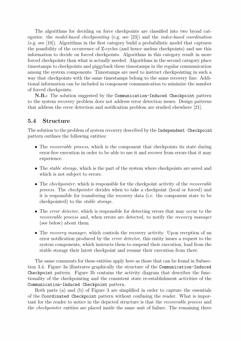
The same comments for these entities apply here as those that can be found in Subsec-tion 3.4. Figure 3a illustrates graphically the structure of the Communication-Induced
Checkpoint pattern. Figure 3b contains the activity diagram that describes the func-tionality of the checkpointing and the consistent state re-establishment activities of theCommunication-Induced Checkpoint pattern.
Both parts (a) and (b) of Figure 3 are simplified in order to capture the essentialsof the Coordinated Checkpoint pattern without confusing the reader. What is impor-tant for the reader to notice in the depicted structure is that the recoverable process andthe checkpointer entities are placed inside the same unit of failure. The remaining three

notifyabouterror
mon
itor
for
erro
r
getstate
unit of failure
save state
susp
end
load
che
ckpo
int
error detectormonitors
recoverable process
checkpointercalculates whether
to save state
recoverable processruns
error detectornotifies
recovery manager
recovery managersuspends all
recoverable processes
recovery managerresumes all
recoverable processes
checkpointer
checkpoint infopiggybacks
in messages sentto other checkpointers
checkpointersaves state tostable storagerecovery manager
recoverable processesreloads last checkpoints to
load
last
che
ckpo
int a
nd r
esum
e [ error ] [ chkpt ]
(a) (b)
errordetector
managerrecovery
checkpointer
processrecoverable
stablestorage
Figure 3: The structure (a) and the activity diagram (b) of the Communication-InducedCheckpoint pattern.
entities are outside that unit of failure, implying that they will not be affected by theoccurrence of an error in either of the two aforementioned entities. Moreover, a recov-erable process corresponds to a distinguishable component in the system. Hence, in asystem there will be as many recoverable processes and checkpointers as the number ofthe constituent system components that are mapped to separate units of failure.
5.5 Implementation
The implementation issues of the Communication-Induced Checkpoint pattern are verysimilar to those of the Independent Checkpoint and Coordinated Checkpoint patternsmentioned respectively in Subsections 3.5 and 4.5.
5.6 Consequences
The Communication-Induced Checkpoint pattern has the following benefits:
+ The time overhead is kept relatively low, both for the checkpointing and the con-

sistent state re-establishment activities of the rollback recovery mechanism.
+ The Communication-Induced Checkpoint pattern does not suffer from the dominoeffect. This means that a system recovery will be completed within bounded time.
+ Communication overhead, in terms of number of exchanged messages, is kept rel-atively low, since this pattern does not require explicit synchronization messagesexchanged among the system components.
+ The space overhead is kept relatively low, since useless checkpoint that can neverbe part of a recovery line are eliminated by the mechanism that takes forced check-points.
The Communication-Induced Checkpoint pattern imposes also some liabilities:
- The volume of the exchanged messages is increased due to the piggybacked times-tamps that the checkpointer adds to each exchanged message.
- Under regular functioning, the Communication-Induced Checkpoint pattern intro-duces more time overhead in error-free executions than the Independent Checkpoint
pattern and more space overhead and time overhead during system recovery thanthe Coordinated Checkpoint pattern. To minimize one of these overheads wouldmean transforming the Communication-Induced Checkpoint pattern to one of theother two patterns, losing thus the combined benefits. Hence, this pattern cannotperform equally well as the best cases of each of the Independent Checkpoint andCoordinated Checkpoint patterns.
5.7 Related Patterns
The Communication-Induced Checkpoint pattern is also specialization of the Rollback
pattern [21], and it has a number of common characteristics with the other two patternspresented in this paper.

6 Epilogue
This paper has presented three design patterns for checkpoint-based rollback recovery,which distill parts of the results on system recovery in distributed systems [8]. This workis a complement to previous work on design pattern for fault tolerance [21] and it can beused to extend the classification of the pattern system presented there. The presentedpatterns offer alternative solutions to the system recovery problem, each at a different costin terms of time, space and communication overhead introduced to the system execution.
The Independent Checkpoint pattern is ideal for the development of systems withdemanding performance constraints during error-free executions, that do not experienceerrors often and when they do they can afford to go off service for repairing the failure.The low cost of the checkpointing activity associated to this pattern does not penalizesignificantly the error-free execution of the system, while the elevated recovery overheadthat this pattern introduces can be tolerated when the system goes off service for repair.
The Coordinated Checkpoint pattern is addressed more to the development of sys-tems that have bounded time constraints (yet not high performance once) on their execu-tion, and they cannot afford long execution delays due to system recovery. In other words,while not reaching very high performance, the system execution characteristics (time andspace) need to keep similar values during error-free execution and system recovery periods.The time overhead introduced by the coordinated checkpointing activity can be adjusted(e.g. by using non-blocking checkpointing techniques or loosely synchronized clocks ifavailable) to keep the time overhead during error-free system execution within the ac-ceptable limits. On the other hand, the very low time overhead of the re-establishmentof a consistent global state after the occurrence of an error will allow the system recoveryactivity to impose minimum performance penalties on system execution.
The Communication-Induced Checkpoint pattern is meant for high-performance real-time systems that can perform general purpose computations (as opposed to those systemthat can perform only special purpose computations such as signal processing). It canalso be tuned to fit in most of the cases where the previous two pattern can be employed,except from those extreme cases where the system requires highly optimum performanceduring error-free executions or highly optimum recovery time after the occurrence of anerror. This pattern improves the weaknesses of the previous two pattern, for the priceof somewhat lower performance compared to the best performance each of the other twopatterns can show.
Acknowledgments
The author would like to thank his shepherd, Lisa DiPippo, for her insightful comments,her time and her patience through the revisions of this paper. Also, the paper owes itsfinal form to the constructive criticism and the suggestions of the participants of theDistributed Real-Time and Embedded Systems focus group in PLoP 2003: Lisa DiPippo,Linda Elkin, Richard Gabriel, Christopher Gill, Robert Hanmer, Jerry James, Chang Liu,Toni Marinucci, Douglas Niehaus, Linda Rising, and Paul Rubel.

References
[1] A. Agbaria and R. Friedman. Virtual-Machine-Based Heterogeneous Checkpointing.Software – Practice and Experience, 32(12):1175–1192, October 2002.
[2] B. Bhargava and L. Shy-Renn. Independent Checkpointing and Concurrent Rollbackfor recovery in Distributed Systems - An Optimistic Approach. In Proceedings of the7th Symposium on Reliable Distributed Systems, pages 3–12, October 1988.
[3] N.S. Bowen and D.K. Pradhan. Virtual Checkpoints: Architecture and Performance.IEEE Transactions in Computers, 41(5):516–525, May 1992.
[4] G. Cao and M. Singhal. On Coordinated Checkpointing in Distributed Systems.IEEE Transactions on Parallel and Distributed Systems, 9(12):1213–1225, December1998.
[5] K.M. Chandy and C.V. Ramamoorthy. Rollback and Recovery Strategies for Com-puter Programs. IEEE Transactions on Computers, 21(6):546–556, June 1972.
[6] M. Chandy and L. Lamport. Distributed Snapshots: Determining Global States ofDistributed Systems. ACM Transaction on Computer Systems, 32(1):63–75, January1985.
[7] F. Cristian and F. Jahanian. A Timestamp-Based Checkpointint Protocol for Long-Lived Distributed Computations. In Proceedings of the 10th Symposium on ReliableDistributed Systems, pages 12–20, October 1991.
[8] E.N. Elnozahy, L. Avisi, Y.-M. Wang, and D.B. Johnson. A Survey of Rollback-Recovery Protocols in Message-Passing Systems. ACM Computing Surveys,34(3):375–408, September 2002.
[9] E.N. Elnozahy, D.B. Johnson, and W. Zwaenepoel. The Performance of Consis-tent Checkpointing. In Proceedings of the 11th Symposium on Reliable DistributedSystems, pages 39–47, October 1992.
[10] J.M. Helary, A. Mostefaoui, A. Netzer, and M. Raynal. Preventing Useless Check-points in Distributed Computations. In Proceedings of the 16th Symposium on Reli-able Distributed Systems, pages 183–190, October 1997.
[11] S.-T. Hsu and R.-C. Chang. Continuous Checkpointing: Joining the Checkpointingwith Virtual Memory Paging. Software – Practice and Experience, 27(9):1103–1120,September 1997.
[12] D.-H. Kim and C.-S. Park. A Communication-Induced Checkpointing AlgorithmUsing Virtual Checkpoint on Distributed Systems. In Proceedings of the 7th Inter-national Conference on Parallel and Distributed Systems, pages 145–150, July 2000.
[13] R. Koo and S. Toueg. Checkpointing and Rollback-Recovery for Distributed Systems. IEEE Transactions on Software Engineering, 13(1):23–31, January 1987.
[14] J. C. Laprie, editor. Dependability: Basic Concepts and Terminology, volume 5 ofDependable Computing and Fault-Tolerant Systems. Springer-Verlag, 1992.

[15] C.C. Li and W.K. Fuchs. CATCH: Compiler-Assisted Techniques for Checkpoint-ing. In Proceedings of the 20th IEEE International Symposium on Fault-TolerantComputing, pages 74–81, 1990.
[16] J. Long, W.K. Fuchs, and J. A. Abraham. Compiler Assisted Static Checkpoint In-sertion. In Proceedings of the 22nd IEEE International Symposium on Fault-TolerantComputing, pages 58–65, July 1992.
[17] V.P. Nelson. Fault-Tolerant Computing: Fundamental Concepts. IEEE Computer,23(7):19–25, July 1990.
[18] R.H. Netzer and J. Xu. Necessary and Sufficient Conditions for Consistent GlobalSnapshots. IEEE Transactions on Parallel and Distributed Systems, 6(2):165–169,February 1995.
[19] R. Prakash and M. Singhal. Low-Cost Checkpointing and Failure Recovery in MobileComputing. IEEE Transactions on Parallel and Distributed Systems, 7(10):1035–1048, October 1996.
[20] B. Randell. System Structure for Software Fault Tolerance. IEEE Transactions onSoftware Engineering, 1(2):220–232, June 1975.
[21] T. Saridakis. A System of Patterns for Fault Tolerance. In Proceedings of the 7thEuropean Conference on Pattern Languages of Programs (EuroPLoP), pages 535–582,June 2002.
[22] R. Strom and S. Yemini. Optimistic Recovery in Distributed Systems. ACM Trans-actions on Computer Systems, 3(3):204–226, August 1985.
[23] Y.-M. Wang. Consistent Global Checkpoints that Contain a Given Set of LocalCheckpoints. IEEE Transactions on Computers, 46(4):456–468, April 1997.