Embed Size (px)
Citation preview

1
Design Patterns as Language Constructs
Jan BoschUniversity of Karlskrona/Ronneby
Department of Computer Science and Business AdministrationS-372 25 Ronneby, Sweden
e-mail: [email protected]: http://www.pt.hk-r.se/~bosch
AbstractDesign patterns have proven to be very useful for the design of object-oriented systems. The power of design pat-terns stems from their ability to provide generic solutions to reappearing problems that can be specialised for partic-ular situations. The implementation of design patterns, however, has received only little attention and we haveidentified four problems associated with the implementation of design patterns using conventional object-orientedlanguages. First, thetraceability of a design pattern in the implementation is often insufficient; often the design pat-tern is ‘lost’. Second, since several patterns require an object to forward messages to other objects to increase flexi-bility, the self problem often occurs. Thirdly, since the pattern implementation is mixed with the domain class, thereusability of pattern implementations is often limited. Finally, implementing design patterns may present signifi-cantimplementation overhead for the software engineer. Often, a, potentially large, number of simple methods hasto be implemented with trivial behaviour, e.g. forwarding a message to another object. In this paper, a solution tothese problems is presented in the context of the layered object model (LayOM). LayOM provides language supportfor the explicit representation of design patterns in the programming language.LayOM is an extended object-ori-ented language in that it contains several components that are not part of the conventional object model, such asstates, categories andlayers. Layers are used to represent design patterns at the level of the programming languageand example layer types for eight design patterns are presented, i.e.Adapter , Bridge , Composite , Facade , State ,Observer , Strategy andMediator . SinceLayOM is an extensible language, the software engineer may extend thelanguage model with abstractions for other design patterns.
1 Introduction
Design patterns are becoming increasingly popular as a mechanism to describe solutions to general design problemsthat can be customised to particular applications. Several authors, e.g. [Gammaet al. 94, Pree 95, Coplien & Schmidt95], have written about the various aspects of design patterns. Several categories of design patterns have been pro-posed for both general, i.e. domain independent, patterns, as well as domain specific patterns. Since our collectiveunderstanding of the object-oriented paradigm is develops continuously, the number of available design patterns isalso growing constantly.
A software engineer uses aparadigm, i.e. a set of related concepts, when designing a system. The size and contents ofthe concept set is depending on the experience of the software engineer. An inexperienced software engineer may justuse the concepts present in the used programming language, whereas an experienced engineer has a much larger set.The popularity of design patterns is based on their ability to capture the design concepts of a experienced softwareengineer, i.e. good designs. Most authors propose design patterns as a mechanism specifically used during design. Therelation to the implementation level is often discussed in terms of example or template code that allows the softwareengineer to conveniently transform the design pattern. In general, a traditional object-oriented language such as C++is used. The disadvantage of a programming language based on the conventional object-oriented paradigm such asC++ is that no support for the representation of design patterns is provided by the language. This leads to problemsrelated to traceability, theself problem, expressiveness and implementation overhead problems related to the imple-mentation of design patterns.
We take the standpoint that design patterns are part of the software engineer’s paradigm and that it is the task of theprogramming language to represent the concepts in the paradigm as accurate as possible. Although it is impossible torepresent all concepts, we believe that, with the proper programming language design, many more concepts, includingseveral design patterns, could be represented by the programming language.
In this paper, the layered object model (LayOM) is proposed as a language model with explicit support for representingdesign patterns.LayOM is a language model that provides explicit support for modelling constructs used during object-

2
oriented design, such asdesign patterns, but alsorelations between objects andabstract object state. An object inLayOM consists, next to instance variables and methods, of states, categories and layers. Layers encapsulate the objectand intercept messages that are send to and by the objects. The layers are organised into classes and each layer classrepresents a concept, such as a relation with another object or a design pattern.LayOM is supported by a developmentenvironment that translates classes and applications defined inLayOM into C++ code. The generated C++ code canthen be used to construct applications, either direct or integrated with existing C++ code. The advantage of usingLayOM instead of a traditional object-oriented language is that it does not suffer from the identified problems related tothe implementation of design patterns.LayOM can be used without losing compatibility with legacy systems and codedeveloped elsewhere as it is translated to C++. The resulting C++ code can be integrated in other code as any C++program.
The remainder of this paper is organised as follows. In the next section, design patterns are introduced and the prob-lems associated with the implementation of design patterns are discussed. In section 3, the layered object model is pre-sented. Section 4 describes the implementation of four structural and four behavioural design patterns as layers ofLayOM. Section 5 compares the presented ideas with related work and the paper is concluded in section 6.
2 Design Patterns
When designing a system, the software engineer makes use of aparadigm, i.e. a set of related concepts. Within theobject-oriented paradigm, concepts such as object, class, method, inheritance, etc. are used to model the system. Aninexperienced engineer generally has a small concept set, primarily consisting of the concepts represented in the usedprogramming language. Somewhat more experienced software engineers have access to larger concept sets, includingthe concepts presents in a typical data structures and algorithms course. After this course, the only way for a student toget access to more advanced concepts is through personal, hands-on experience. The popularity of design patterns, webelieve, stems from their ability to capture such implicit experience and make it shared by the (object-oriented) soft-ware engineering community.
Patterns, as a concept, originate from the work by Christopher Alexander [Alexander et al. 77]. Each pattern describesa recurring problem and a generic solution that can be adopted for particular situations. A set of patterns can be organ-ised in apattern language, thus providing a set of composable solutions for problems in a particular domain.
The patterns notion has been adopted in object-orientation asdesign patterns. [Gamma et al. 94] define design pat-terns asdescriptions of communicating objects and classes that are customised to solve a general design problem in aparticular context. The authors present a catalogue of 23 design patterns, organised in three categories depending onthe pattern’s purpose.Creational patterns are concerned with object creation, whereasstructural patterns address thecomposition of classes and objects.Behavioural patterns are concerned with the ways in which classes or objectsinteract and distribute responsibility.
However, the domain of patterns is not limited to the design patterns discussed by [Gamma et al. 94]. For example,[Pree 95] discusses, next to the design pattern catalogue by [Gamma et al. 94], object-oriented patterns [Coad 92],coding patterns, framework cookbooks and formal contracts [Helm et al. 90] as patterns for solving general designproblems. [Buschmann et al. 96] classifies design patterns according to granularity, functionality and structural princi-ples. For example, three levels of granularity are recognised, i.e.architectural frameworks, design patterns andidi-oms. Also, in [Coplien & Schmidt 95] and [Vlissides et al. 95], several design pattern related papers are presented.Due to the fact that design patterns have only recently become popular in the object-oriented community, no generallyaccepted classification of design patterns exists.
An issue seldom addressed by the design pattern community is the implementation support for design patterns. Sincedesign patterns are part of the set of concepts, i.e. the paradigm, used by a software engineer for modelling systems,the engineer would benefit from handling design patterns as first-class entities both during design and implementa-tion. I.e. a pattern used during design should be implementable as an identifiable unit in the programming language.The goal of a programming language design is to represent the concepts in the software development paradigm asaccurately as possible.
When implementing design patterns using a conventional object-oriented language, e.g. C++, one can identify severalproblems. The problems we identified are discussed in the next section, but the underlying problem is that the designpattern cannot be represented as a first-class entity. Since a design pattern often affects multiple aspects, e.g. methods,of a class, or even multiple classes or objects, a pattern language construct often cannot be inherited or composed in

3
the traditional way. More powerful composition techniques are required that allow the design pattern to superimposeits behaviour on a class or object, while both the pattern and the domain entity remain identifiable entities.
2.1 Problems of Implementing Design Patterns
We focus in this paper on the implementation in an object-oriented language of the design patterns that are containedin an object-oriented design model. We have experienced problems when implementing the design patterns in a tradi-tional object-oriented language as C++. These problems are primarily related to the traceability of design patterns inthe implementation, the self problem, language expressiveness and the implementation overhead of design patterns.
• Traceability : The traceability of a design pattern is often lost because the programming language does not supporta corresponding concept. The software engineer is thus required to implement the pattern as distributed methodsand message exchanges, i.e. the pattern which is a conceptual entity at the design level is scattered over differentparts of an object or even multiple objects. This problem has also been identified by [Soukup 95].
• Self problem: The implementation of several design patterns requires forwarding of messages from an objectreceiving a message to an object implementing the behaviour that is to be executed in response to the message.The receiving object can, for example, be an application domain object which delegates some messages to a strat-egy object. However, once the message is forwarded, the reference to the object originally receiving the messageis no longer available and references to self refer to the delegated object, rather than to the original receiver of themessage. The problem is known as the self problem [Lieberman 86].
• Reusability: Design patterns are primarily presented as design structures. Since design patterns often cover sev-eral parts of an object, or even multiple objects, patterns have no first class representation at the implementationlevel. The implementation of a design pattern can therefore not be reused and, although its design is reused, thesoftware engineer is forced to implement the pattern over and over again.
• Implementation Overhead: The implementation overhead problem is due to the fact that the software engineer,when implementing a design pattern, often has to implement several methods with only trivial behaviour, e.g. for-warding a message to another object or method. This leads to significant overhead for the software engineer anddecreased understandability of the resulting code.
Examples of these problems can be found in section 4. To address these problems, we propose a solution within thecontext of the layered object model, discussed in section 3. The layered object model is an extensible object modeland its objects are encapsulated by so-calledlayers. In this paper, we illustrate how a design pattern can be imple-mented as a layer type. The software engineer can instantiate the layer type corresponding to a design pattern andassociate a specification with the layer that specialises the behaviour of the layer type for the particular context. Weillustrate our approach by applying it to eight design patterns from the design pattern catalogue by [Gamma et al. 94].The reason for using this catalogue is that the semantics of these design patterns are relatively well defined andaddress relevant design problems.
3 Layered Object Model
The layered object model is an extended object model, i.e. it defines additional components next to the traditionalobject model components such as layers, states and categories. In figure 1, an exampleLayOM object is presented. Thelayers encapsulate the object, so that messages send to or by the object have to pass the layers. Each layer, when itintercepts a message, converts the message into a passive message object and evaluates the contents to determine theappropriate course of action. Layers can be used for various types of functionality. Layer classes have been defined

4
for the representation of relations between objects, discussed in section 3.1 and 3.2. In this paper, we present the rep-resentation of design patterns through the use of layers.
Figure 1. The layered object model
A LayOM object contains, as any object model, instance variables and methods. The semantics of these components isvery similar to the conventional object model. The only difference is that instance variables can have encapsulatinglayers adding functionality to the instance variable. In figure 2, an exampleLayOM classTextEditWindow is shown,containing one instance variableloc .
A state in LayOM is an abstraction of the internal state of the object. InLayOM , the internal state of an object is referredto as theconcrete state. Based on the object’s concrete state, the software engineer can define an externally visibleabstraction of the concrete state, referred to as the abstract state of an object. The abstract object state is generally sim-pler in both the number of dimensions, as well as in the domains of the state dimensions. In figure 2, the abstract statedistFromOrigin is shown. It abstracts the location of the mouse and the window origin into a distance measure. Werefer to [Bosch 96b] for an extended description of abstract object state.
A category is an expression that defines a client category. A client category describes the discriminating characteris-tics of a subset of the possible clients that should be treated equally by the class. For example, the class in figure 2defines aProgrammer client category, restricting the use of the object to instances of classProgrammer and its sub-classes. The behavioural layer types use categories to determine whether the sender of a message is a member of a cli-ent category. If the sender is a member, the message is subject to the semantics of the specification of the behaviourallayer type instance.
A layer, as mentioned, encapsulates the object and intercepts messages. It can perform all kinds of behaviour, either inresponse to a message or otherwise. Previously, layers have primarily been used to represent relations betweenobjects. InLayOM , relations have been classified into structural relations, behavioural relations and application-domain relations.
Structural relation types define the structure of a class and providereuse. These relation types can be used toextendthe functionality of a class. Inheritance and delegation are examples of structural relation types.
The second type of relations are thebehavioural relations that are used to relate an object to its clients. The function-ality of the class is used by client objects and the class can define a behavioural relation with each client (or client cat-egory). Behavioural relationsrestrict the behaviour of the class. For instance, some methods might be restricted tocertain clients or in specific situations.
The third type of relations areapplication domain relations. Many domains have, next to reusable application domainclasses, also application domain relation types that can be reused. For instance, thecontrols relation type is a veryimportant type of relation in the domain of process control. In the following two sections, structural and behaviouralrelation layer types will be discussed. For information on application-domain relation types, we refer to [Bosch 95,Bosch 96a].

5
The class in figure 2 has three layers. ThePartOf layer defines an instance ofTextEditor as a part of the class. ThePartialInherit layer defines that classTextEditWindow inherits all methods from classWindow, except methodmoveOrigin . TheRestrictState layer restricts access to instances of classProgrammer and its subclasses, but onlyif the distance between the mouse location and the window origin is less than 100 units.
class TextEditWindowlayers
rs : RestrictState(Programmer, accept all when distFromOrigin<100 otherwise reject);pin : PartialInherit(Window, *, (moveOrigin));po : PartOf(TextEditor);
variablesloc : Location;
methodsmoveOrigin(newLoc : Location) returns Boolean
beginloc := newLoc;self.updateWindow;
end;states
distFromOrigin returns Pointbegin return ((lox.x - self.origin.x).sqr + (lox.y - self.origin.y).sqr).sqrt; end;
categoriesProgrammer
begin sender.subClassOf(Programmer); end;end; // class TextEditWindow
Figure 2. ExampleLayOM class TextEditWindow
Next to an extended object model, the layered object model is also anextensible object model, i.e. the object modelcan be extended by the software engineer with new components.LayOM can, for example, be extended with new layertypes, but also with structural components, such asevents. The notion of extensibility, which is a core feature of theobject-oriented paradigm, has been applied to the object model itself. Object model extensibility may seem useful intheory, but in order to apply it in practice it requires extensibility of the translator or compiler associated with the lan-guage. In the case ofLayOM , classes and applications are translated into C++. The generated classes can be combinedwith existing, hand-written C++ code to form an executable. TheLayOM compiler is based ondelegating compilerobjects[Bosch 96c], a concept that facilitates modularisation and reuse of compiler specifications and extensibility ofthe resulting compiler. The implementation of theLayOM compiler is discussed in section 3.3.
3.1 Structural Relation Layers
Structural relation types, as described above, define thestructure of an application. A class uses the structural rela-tions toextend its behaviour and the class can be seen as theclient, i.e. the class that obtains functionality provided byother classes. Generally, three types of structural relations are used in object-oriented systems development:inherit-ance, delegation andpart-of. These types of relation all provide some form ofreuse. The inherited, delegated or partobject provides behaviour that is reused by, respectively, the inheriting, delegating or whole object. Therefore, next toreferring to these relation types asstructural, we can also define them asreuse relations.
Orthogonal to the discussed relation types one can recognise two additional dimensions of describing the extendedbehaviour of an object, i.e.conditionality, andpartiality. Conditionality indicates that the reusing object limits thereuse to only occur when it is in certain states. Partially indicates that the reusing object reuses only part of the reusedobject.
We consider it very important that a relation between two classes or objects, regardless of its complexity, is modelledas a single entity within the model. An alternative approach would be to define a collection of orthogonal constructsand to decompose a relation between objects into instances of each orthogonal construct. This approach does, how-ever, not represent a conceptual entity in analysis and design as an entity in the language model.
The different aspects of a structural relation, i.e. its type, partiality and conditionality, form a three-dimensional spacewhich contains all possible combinations. In compliance with our modelling principle, we define a relation type foreach combination. This results in twelve structural relation types. These structural relation types are shown in table 1.

6
Due to space constraints, it is not possible to describe the syntax and semantics of all structural relation types. Instead,one layer of type Partial Inheritance is described in detail. The semantics of the other layer types can be deduced bythe reader.
Table 1. Structural relation type identifiers
In figure 2, class TextEditWindow contains a partial inheritance layer with the following configuration:
pin: PartialInherit(Window, *, (moveOrigin));
The semantics of the partial inheritance layer is, that a part of the interface of the inherited class is reused or excluded.The name of this layer is pin and its type is PartialInherit . The layer type accepts three arguments. The first argu-ment is the name of the class that is inherited from; Window in this case. The second argument is a ‘*’ or a list of inter-face elements and indicates the interface elements that are to be inherited. The ‘*’ in this example indicates that allinterface elements are inherited. The third argument can also contain a ‘*’ or a list of interface elements. In this exam-ple, the list only consists of one element: moveOrigin . The semantics of layer pin is that classTextEditWindow inher-its the complete interface of class Window, except for moveOrigin .
Note that, different from other object-oriented languages, the software engineer has to explicitly specify which inter-face elements of the superclass are to be inherited (or reused). A method is not automatically overridden by subclassmethod with the same name.
In figure 3, the implementation of this semantics is illustrated. The partial inheritance layer is the second layer of classTextEditWindow . There is the most outer layer, shown around layer pin and an inner layer, shown around TextE-
ditWindow . All inheritance layers create an instance of the inherited superclass. In figure 3, an instance of class Win-
dow is shown. The layer contains a message handler, that, for each received message, determines whether the messageis passed on inwards or outwards or that it is redirected to the instance of class Window. In the figure, an incomingmessage is shown. The message is reified and handed to the message handler. The message handler reads the selectorfield of the message and compares it with the (partially) inherited interface of class Window. If the selector is part ofthe set of interface elements, the message is redirected to the instance of class Window (situation (b) in figure 3). If theselector does not match with the interface of classWindow, it is not redirected but forwarded to the next layer (situation(a) in figure 3).
Figure 3. The PartialInherit layer
For an extensive description of the semantics of the other structural relation types we refer to [Bosch 95, Bosch 96a].
3.2 Behavioural Relation Layers
In the previous section, we discussed relations where the object containing the relation is the client, i.e. the object‘extends’ itself with the structural relations. In this section we discuss relation types between the object and its clients.These relation types, generally, constrain the access of clients and the behaviour of the object in some way.
relation type inheritance delegation part-of
default Inherit Delegate PartOf
conditionality ConditionalInherit ConditionalDelegate ConditionalPartOf
partiality PartialInherit PartialDelegate PartialPartOf
conditional and partial CondPartInherit CondPartDelegate CondPartPartOf

7
In order to keep the type and number of clients of the object open ended, we define client categories and for each mes-sage is determined whether the sender of the message is a member of a client category. The message is then subject tothe behavioural relation(s) defined for that client category.
A relation between the object and a client category can be defined by a number of behavioural constraints. The typesof constraints areclient-based access, state-based access, concurrency andreal-time. The layered object model takesa different approach to defining modelling constructs when compared to the conventional approaches. Rather thanaiming at defining ‘clean’, orthogonal constructs, we try to define constructs that correspond to conceptual entities.Hence, we are convinced, supported by the object-oriented analysis and design methods, that the concept of a relationbetween objects is a conceptual entity and that the different aspects of this relation should be defined as part of thisrelation, rather than as several unrelated orthogonal constructs that, when combined, provide equivalent behaviour.
In table 2, the behavioural relation (or layer) types are shown. Each relation type can be viewed as a location in thespace build by the four constraint dimensions defined above. However, a relation always requires a client category tobe specified. This results in three dimensions which can be part of or not part of the relation. For each combination, arelation type is defined.
Table 2. Behavioural relation type identifiers
Again, due to space constraints, we are unable to discuss the semantics of all behavioural relation types. Instead, wewill discuss the semantics of theRestrictState layer type in detail.
TheRestrictState layer type restricts the access for a particular client category when the object is in a certain states.ClassTextEditWindow (see figure 2) has aRestrictState layer with the following configuration syntax:
rs : RestrictState(Programmer, accept all when distFromOrigin < 100 otherwise reject);
The semantics of this layer specification is the following. Clients that are classified as members of theProgrammer
client category can access all methods of the object provided thatdistFromOrigin is less than or equal to 100. If it islarger than 100, the message is rejected, i.e. an error message is returned to the client object that sent the message.
In figure 4, the functionality of theRestrictState layer type is presented graphically. The layer will intercept mes-sages sent to the object. If the message is sent by an object that is not classified as a member of the client category thatis indicated by the layer specification, the message will just be passed on to the next layer. Otherwise, the selector ofthe message is matched with the identifier list in the layer specification. If it matches, the state that is referred to in thespecification is evaluated. Depending on the use of the keywordunless or when, the message will be passed on to thenext layer (see (a) in figure 4). If the message is not passed on, the message is stored in the message queue if thedelay
keyword is used (see (b) in figure 4) or, in case of the use of keywordreject , the message is discarded and an errormessage is sent to the sender object (see (c) in figure 4).
Figure 4. TheRestrictState layer
No factor One factor Two factors Three factors
RestrictClient RestrictState RestrictStateAndConc RestrictStateConcAndTime
RestrictConc RestrictStateAndTime
RestrictTime RestrictConcAndTime

8
3.3 Implementation
As mentioned earlier, the layered object model is both anextended and anextensible object model. Extended, since itcontains components in addition to the components of the traditional object model, i.e. states, categories and layers.Extensible, since it may be extended with new components whenever the software engineer considers it to be appro-priate. Possible extensions are new layer types, but also new object components such as events. Over the years, prima-rily new layer types for the representation of structural and behavioural inter-object relations, acquaintance handlingand, the topic of this paper, design patterns have been defined. However, over time it may become clear that the layertypes for design pattern represented proposed in the next section lack expressiveness for particular situations or shouldbe implemented differently. In response to this, the language should be extended or changed to reflect these newrequirements. In conventional object-oriented languages this, would be very complex due to the monolithic, rigidcompiler technology that is used to construct compilers for these languages. However, it is important to make clearthat the rigidness of conventional programming languages is due to technological problems, i.e. compiler technology,and not due to conceptual or other human factors. The software engineer, while modelling a domain, ideally is able torepresent each domain concept with a corresponding concept in the programming language.
Since traditional compiler technology is unsuitable to implement extensible languages, an alternative approach had tobe defined. The implementation of the layered object model is based on the notion ofdelegating compiler objects(DCOs) [Bosch 96c]. A DCO is an object that compiles a part of the syntax of the input language. It consists of one ormore lexers, one or more parsers and a parse graph. The nodes in the parse graph have the ability to generate code forthemselves. In case of theLayOM class compiler, it consists of a class DCO, method DCO, state DCO, category DCOand a DCO for each layer type. Each DCO definition results in a class and a DCO object can instantiate another DCOand delegate control to it. The delegated DCO will perform its functionality and return control to the delegating DCOwhen it is finished. TheLayOM compiler DCOs generate C++ output code.LayOM code is either a class or an application.A LayOM class is compiled into a C++ class and aLayOM application is compiled into a C++ main program. The gener-ated C++ class can be incorporated in any C++ function and, subsequently, into an executable program. The structureof theLayOM compiler is shown in figure 5.
Figure 5. Overview of theLayOM compiler
An advantage of using the DCO approach is that it supports extensibility of the language very well. When the softwareengineer wants to add a new concept to the language, all that is required is a DCO defining the syntax and code gener-ation information of that particular concept. The new DCO is added to the set of DCOs in the existing compiler and itcan be used. Except for some minor modifications in the DCOs that should instantiate the new DCO, no changes arerequired.
The delegating compiler objects concept is supported by a tool that allows the software engineer to compose compil-ers by instantiating one or more DCOs. Each DCO can subsequently be assigned a lexer and a parser. Each compilerhas a base DCO that is initially instantiated. The tool also provides editing facilities for specifying parsers, lexers andparse graph node classes. For a more detailed description of the delegating compiler object concept and the associatedtool, we refer to [Bosch 96c].
4 Design Patterns as Language Constructs
Most design patterns have a well-defined semantics that could be used as the basis for defining language constructsthat explicitly support the representation of the design pattern in the programming language. However, it should be

9
noted that some researchers and engineers have the opinion that design patterns should be used as design guidelinesthat are adapted to each application. As a consequence, design patterns are considered not sufficiently specific andcontain too much application specific aspects once applied that it is infeasible to represent them as language con-structs. We disagree with this point of view. To us, design patterns belong to the paradigm used by experienced soft-ware engineers. Since the primary aim of programming languages should be to provide accurate language constructsfor all those paradigm concepts that can be logically integrated in the language. The argument that this would increasethe complexity of the language does not hold since the programming language represents the paradigm concepts usedby the software engineer. Therefore, it is the lack of expressive constructs for paradigm concepts that will increasecomplexity, since the engineer will be forced to implement the concept in terms of lower level language constructs,thereby reducing traceability and understandability. Furthermore, a software engineer is free to use the available lan-guage constructs but is not forced! While obtaining experience, many programming students increase the set of lan-guage constructs they use to build their programs. A similar development one might expect in languages that provideexpressiveness for design patterns.
The above discussion brought us to the understanding that it is beneficial for a programming language to provide con-structs for representing design patterns. However, we have identified problems associated with the implementation ofpatterns in the conventional object-oriented languages. These languages, like C++, provide insufficient support toimplement design patterns in a traceable, efficient manner. Traceability is problematic because several design patternsare lost during implementation. Secondly, several pattern implementation involve the forwarding of messages, caus-ing the self problem. Thirdly, implementations of patterns in programming languages such as C++ are generally notreusable. Finally, since several design patterns require the definition of a, potentially large, number of methods withvery trivial behaviour, e.g. forwarding a message to a nested object, the software engineer is forced to implement allthese methods causing considerable implementation overhead.
To address these problems, the approach taken in this paper is to provide design patterns with a first-class implemen-tation construct corresponding to the conceptual design entity a pattern represents. However, first-class design patternimplementations require a more advanced language model than the conventional object-oriented model. The behav-iour of a design pattern is, in a way,superimposed on the object behaviour and a language model that allows fordesign pattern representation should provide corresponding composition techniques. In this section, we present anumber ofLayOM layer types that represent design patterns. The design patterns have been selected from the collec-tion defined by [Gamma et al. 94], in particular from the structural and behavioural design patterns. Since the collec-tion contains seven structural design patterns and 11 behavioural design patterns, we are unable to describe layer typesfor all these design patterns for reasons of space. Instead, we limit ourselves to describing those design patterns thatare most illustrative and suitable to be presented as layer types. In this section, eight design patterns are discussed;four structural and four behavioural patterns.
4.1 Structural Design Patterns
As described in section 2, the structural design patterns are used to define parts of the structure of the system. Thesepatterns are concerned with the composition of classes and objects. In [Gamma et al. 94], seven design patterns aredescribed. However, as mentioned, traditional object-oriented languages have difficulty in implementing design pat-terns in a traceable and efficient manner. The solution proposed in this paper is to make use of the layered objectmodel for the implementation of design models that make use of patterns. AsLayOM is an extensible object model, theobject model can be extended by, among others, adding new layer types. We have used this facility to define layertypes that implement the functionality of design patterns. In the following sections, theAdapter , Bridge , Composite
andFacade pattern are discussed.
4.1.1 Adapter
Intent. Theadapter design pattern is used to convert the interface of a class into another interface that is expectedby its clients. The adapter design pattern allows classes to cooperate that otherwise would be incompatible due to thedifferences in expected interfaces.

10
Problem. In a conventional object-oriented language, the adapter is implemented as an object that forwards thecalls, after adaptation, to the adaptee, i.e. the adapted object. In figure 6, the structure of an adapter for object adapta-tion as presented in [Gamma et al. 94] is shown. Class adaptation is not shown in this figure.
Figure 6. Structure of Adapter design pattern
Although theadapter indeed allows classes to work together that otherwise could not, there are some disadvantagesassociated with the implementation of the pattern. One disadvantage is that for every element of the interface thatneeds to be adapted, the software engineer has to define a method that forwards the call to the actual methodSpe-
cificRequest . Moreover, in case of object adaptation, also those requests that otherwise would not have requiredadaptation have to be forwarded as well, due to the intermediate adapter object. This leads to implementation over-head for the software engineer, suffers from the self problem and lacks expressiveness. Also, since behaviour of theadapter pattern is mixed with the domain related behaviour of the class, traceability is reduced.
Solution. In the layered object model, the functionality of theAdapter design pattern does not require a separateobject (or class) to be defined. Instead, a layer of typeAdapter is defined that provides the functionality associatedwith the design pattern. The layer can be used as part of a class definition, in which case it represents class adaptation.It can also be defined for an object thus representing object adaptation. The syntax of layer typeAdapter is the fol-lowing:
<id> : Adapter( accept <mess-sel>+ as <new-mess-sel>, accept <mess-sel>+ as <new-mess-sel>, ...);
The semantics of the layer type is that a message with a message selector<mess-sel> that is specified in the layer ispassed on with a new selector<new-mess-sel> . Theadapter layer type also allows more than one message selectorto be translated to a new message selector. The layer will translate both messages send to the object encapsulated bythe layer and messages send by the object.
The Adapter layer can be used for class adaptation by defining a new adapter class consisting only of two layers.Below, an example classadapter is shown:
class adapterlayers
adapt : Adapter( accept mess1 as newMessA, accept mess2, mess3 as newMessB);inh : Inherit(Adaptee);
end; // class adapter
The example classadapter translates amess1 message into anewMessA message and amess2 or mess3 message intoa newMessB message. The methodsnewMessA andnewMessB are presumably implemented by classAdaptee and theInherit layer will redirect these and other messages to the instance of classAdaptee that is contained within thelayer.
Adaptation at the object level can be achieved by encapsulating the object with an additional layer upon instantiation.In this case, the adaptation will only be effective for this particular instance and not for the other instances of the sameclass. Below, an example of an adapted object declaration is shown.
...// object declarationadaptedAdaptee : Adaptee with layers
adapt : Adapter( accept mess1 as newMessA, accept mess2, mess3 as newMessB);end;...
client target
Request()
adapter
Request() adaptee->SpecificRequest()
adaptee
SpecificRequest()

11
The instanceadaptedAdaptee will be extended with an additional layer of typeAdapter that adapts its interface tomatch the interface expected by its clients. TheAdapter layer will be the most outer layer of the object, interceptingall messages going into and out of the object.
Layer typeAdapter can also be used in an inverted situation, i.e. a situation where a single client needs to access sev-eral server objects, but the client expects an interface different from the interface offered by the server objects. In thiscase, the client object (or its class) can be extended with anAdapter layer translating messages send by the client intomessages understood by the server objects.
Evaluation. TheAdapter layer type allows the software engineer to translate theAdapter design pattern directlyinto the implementation, without losing the pattern. There is a clear one-to-one relation between the design and theimplementation. A second advantage is that the software engineer is not required to define a method for every methodthat needs to be adapted. The specification of the layer is all that is required. In addition, in case of object adaptation,the software engineer, in the traditional implementation approach, also needs to define a method for the methods ofthe adapted class that do not have to be adapted. When using theAdapter layer, this is avoided.
A disadvantage of theAdapter layer type definition presented in this paper is that the arguments of the message willbe passed on as sent. In some situations, one would like to pass the arguments on in a different order or add or removesome arguments.
4.1.2 Bridge
Intent. TheBridge pattern decouples an abstraction from the implementation of the abstraction so that the two canvary independently.
Problem. The structure of a class employing the bridge design pattern is shown in figure 7. The relevant methods inthe abstraction forward their calls to the part object containing the implementation. Although the bridge pattern allowsto separate the abstraction from the implementation, at least three problems can be identified with this approach. Thefirst problem is the implementation overhead resulting from the separation between the abstraction and the implemen-tation. Each method in the abstraction class needs to forward the message to the corresponding method in the imple-mentation class. The second problem is theself problem, i.e. once the abstraction class has called the implementationclass, every call to self is directed to the implementation class. This excludes the possibility for the abstraction class tocatchself calls and change the implementation of a particular method. The third problem is related to traceability; theimplementation of the bridge pattern is distributed over the object and there is no one-to-one correlation between thepattern and the implementation structure.
Figure 7. Structure of theBridge design pattern
Solution. In LayOM , this problem is addressed through theBridge layer type that allows the software engineer tospecify for each message by whichobject.method combination it should be implemented. The syntax of theBridge
layer type is the following:
<id> : Bridge(implement <mess-sel>+ as [<object>.]<method>, ...);
The layer intercepts all messages matching <mess-sel> and redirects the message to the indicated object and method.More than one message selector can be redirected to the same object and method. The layer is implemented such thatthe self pseudo variable references the object encapsulated by theBridge layer rather than the object that is redi-rected to, thereby avoiding theself problem.
Abstractionoperation
ImplementoroperationImp
imp
imp->operationImp
RefinedAbstraction ConcreteImplA
operationImp
ConcreteImplB
operationImp

12
TheBridge layer type can be used in two ways, i.e. a class-based and an object-based approach. An example of theclass based approach is shown below.
class Abstractionlayers
bridge : Bridge( implement mess1 as imp.mess1, implement mess2, mess3 as imp.mess2);...
methodsimplementation(anImp : Implementor)
beginimp := anImp;
end;variables
imp : Implementor;end; // class Abstraction
One can also use individual objects and extend them with an implementation, i.e. the object-based approach. In theexample below, the object representing an abstraction is extended with a bridge layer and a part-of layer, providingthe implementation and a bridge to the implementation.
...anAbstraction : Abstraction with layers
bridge : Bridge( implement mess1 as imp.mess1, implement mess2, mess3 as imp.mess2);imp : PartOf(ConcreteImplA);
end;...
Evaluation. The design pattern removes the implementation overhead for the forwarding methods in the abstrac-tion. In addition, since the layered object model supports true delegation of messages, the self problem is not present.Finally, the traceability of the design pattern increases when using theBridge layer type compared to the conven-tional implementation.
4.1.3 Composite
Intent. TheComposite design pattern supports the organisation of objects into part-whole hierarchies. The resultingobjects present a uniform interface to clients, whether the object is an individual object or a composition of objects.
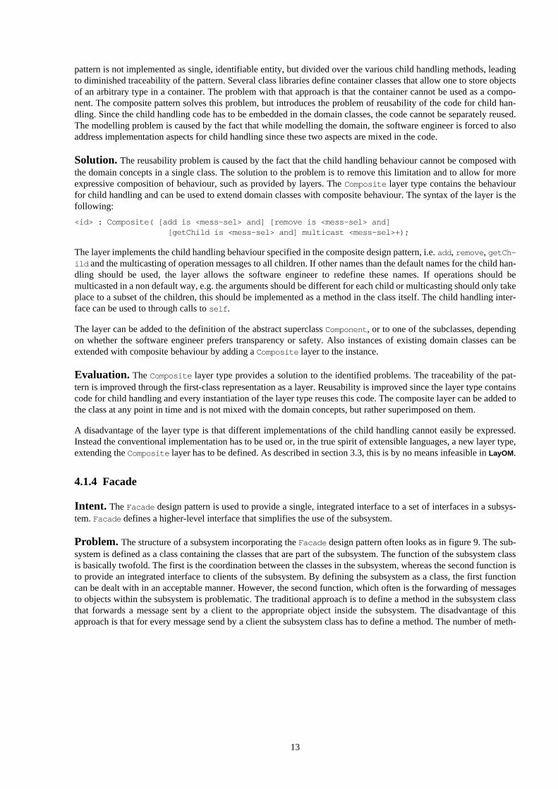
Problem. The Composite pattern has a structure as shown in figure 8. The pattern can be used in two ways, i.e.maximizing safety or transparency. Transparency is optimal if the superclassComponent provides implementationsfor child handling, e.g.Add andRemove. However, since these methods have no meaning for leaf classes, these meth-ods should only be invoked on composites. Therefore, safety is increased when the child handling methods are onlyimplemented in thecomposite class, but this decreases transparency.
Figure 8. Structure of theComposite pattern
TheComposite design pattern is an important pattern that has proven its use in many applications. However, we iden-tified three problems associated with the pattern; related to traceability, reusability and modelling. TheComposite
Componentoperationadd(Component)remove(Component)getChild(int)
Client
Leafoperation forall g in children
g.operation
childrenCompositeoperationadd(Component)remove(Component)getChild(int)
13
pattern is not implemented as single, identifiable entity, but divided over the various child handling methods, leadingto diminished traceability of the pattern. Several class libraries define container classes that allow one to store objectsof an arbitrary type in a container. The problem with that approach is that the container cannot be used as a compo-nent. The composite pattern solves this problem, but introduces the problem of reusability of the code for child han-dling. Since the child handling code has to be embedded in the domain classes, the code cannot be separately reused.The modelling problem is caused by the fact that while modelling the domain, the software engineer is forced to alsoaddress implementation aspects for child handling since these two aspects are mixed in the code.
Solution. The reusability problem is caused by the fact that the child handling behaviour cannot be composed withthe domain concepts in a single class. The solution to the problem is to remove this limitation and to allow for moreexpressive composition of behaviour, such as provided by layers. TheComposite layer type contains the behaviourfor child handling and can be used to extend domain classes with composite behaviour. The syntax of the layer is thefollowing:
<id> : Composite( [add is <mess-sel> and] [remove is <mess-sel> and][getChild is <mess-sel> and] multicast <mess-sel>+);
The layer implements the child handling behaviour specified in the composite design pattern, i.e.add, remove , getCh-
ild and the multicasting of operation messages to all children. If other names than the default names for the child han-dling should be used, the layer allows the software engineer to redefine these names. If operations should bemulticasted in a non default way, e.g. the arguments should be different for each child or multicasting should only takeplace to a subset of the children, this should be implemented as a method in the class itself. The child handling inter-face can be used to through calls toself .
The layer can be added to the definition of the abstract superclassComponent , or to one of the subclasses, dependingon whether the software engineer prefers transparency or safety. Also instances of existing domain classes can beextended with composite behaviour by adding aComposite layer to the instance.
Evaluation. The Composite layer type provides a solution to the identified problems. The traceability of the pat-tern is improved through the first-class representation as a layer. Reusability is improved since the layer type containscode for child handling and every instantiation of the layer type reuses this code. The composite layer can be added tothe class at any point in time and is not mixed with the domain concepts, but rather superimposed on them.
A disadvantage of the layer type is that different implementations of the child handling cannot easily be expressed.Instead the conventional implementation has to be used or, in the true spirit of extensible languages, a new layer type,extending theComposite layer has to be defined. As described in section 3.3, this is by no means infeasible inLayOM .
4.1.4 Facade
Intent. TheFacade design pattern is used to provide a single, integrated interface to a set of interfaces in a subsys-tem.Facade defines a higher-level interface that simplifies the use of the subsystem.
Problem. The structure of a subsystem incorporating theFacade design pattern often looks as in figure 9. The sub-system is defined as a class containing the classes that are part of the subsystem. The function of the subsystem classis basically twofold. The first is the coordination between the classes in the subsystem, whereas the second function isto provide an integrated interface to clients of the subsystem. By defining the subsystem as a class, the first functioncan be dealt with in an acceptable manner. However, the second function, which often is the forwarding of messagesto objects within the subsystem is problematic. The traditional approach is to define a method in the subsystem classthat forwards a message sent by a client to the appropriate object inside the subsystem. The disadvantage of thisapproach is that for every message send by a client the subsystem class has to define a method. The number of meth-

14
ods might easily grow very large and defining these methods is much work for just forwarding a message. A seconddisadvantage is that the traceability of the design pattern in the implementation is lost.
Figure 9. Structure of theFacade design pattern
Solution. As a solution to the identified problems associated with the traditional implementation approach one can,within the layered object model, make use of theFacade layer type. TheFacade layer type provides the functionalityof forwarding messages to objects that are part of the subsystem. A layer of typeFacade is defined as follows:
<id> : Facade(forward <mess-sel>+ to <object>, forward <mess-sel>+ to <object>, ...);
The behaviour of aFacade layer is the following. It matches the selector of the message with the message selectorsdefined in<mess-sel>+ , the message will be forwarded to the object<object> . TheFacade layer can contain severalforwarding elements, allowing the subsystem class to forward to several objects using a singleFacade layer.
A subsystem class using aFacade layer can be defined as follows:
class FacadeExamplelayers
face : Facade( forward mess1, mess2 to PartO1, forward mess3 to PartO2);PartO1 : PartOf(ClassOfO1);PartO2 : PartOf(ClassOfO2);
...end; // class FacadeExample
As described in section 3, the layered object model models relations between objects as layers. These relations includethepart-of relation, which is implemented as thePartOf layer type. TheFacade layer forwards messages matchingmess1 andmess2 to PartO1 , which is an object contained in the subsystem. Messages matchingmess3 are forwardedto objectPartO2 .
Evaluation. The use of theFacade layer type has two main advantages over the traditional implementation tech-niques. The first advantage is that the software engineer does not have to define a, possibly large, number of trivialmethods that just pass on a message to one of the objects in the subsystem. The second advantage is that there is adirect correspondence between the design pattern that is used at the design level and theFacade layer defined in theimplementation.
4.2 Behavioural Design Patterns
Behavioural design patterns focus on algorithms and cooperation and interaction between objects. In addition to thestructure of a group of objects and classes, these design patterns are concerned with the communication between theseobjects and classes. In [Gamma et al. 94] the collection of behavioural design patterns consists of 11 patterns. As men-tioned earlier, four of behavioural design patterns are discussed in this section, i.e.State , Observer , Strategy andMediator .
4.2.1 State
Intent. TheState pattern is used in situations where the behaviour of the object depends on the internal state of theobject. Thus, when the object changes a relevant aspect of its state, it changes behaviour.
Problem. The implementation approach suggested by [Gamma et al. 94] is to define an abstract superclass definingthe methods that change behaviour, depending on the state. This class is subclassed by as many concrete subclasses as
facade

15
there are different relevant states and associated behaviours. These classes are used by the object that is supposed toshow state-dependent behaviour, referred to asContext . TheContext object always contains an instance of one of theconcrete state subclasses. When theContext object changes state, it replaces the instance with an instance of anotherconcrete subclass. In figure 10, the structure of theState design pattern is shown.
Figure 10. Structure of theState design pattern
Although this implementation approach is very appropriate within the traditional object-oriented languages, theapproach has, at least two problems associated with it. The first problem is that this approach assumes that there is arelatively small number of boolean states, that all require a unique implementation for each method in the set of state-dependent methods. However, in several cases the required dynamicity in the object behaviour is not as well struc-tured as this. We refer to [Bosch 96b] for a more extended discussion of these problems. The second problem is thatthe Context object has to implement a trivial method for each state-dependent method implemented by theState
class, resulting in the self problem and implementation overhead for the software engineer. Finally, traceability of theimplementation of the pattern is far from optimal.
Solution. Similar to the solutions presented for the problems associated with the aforementioned design patterns,we define a layer of typeState that allows the software engineer to specify, depending on the object state, the appro-priate method or object for a message requesting state-dependent behaviour. As described in section 3,LayOM pro-vides the notion ofabstract state. Abstract state is an abstraction of the internal, concrete object state that presents therelevant state of an object at its interface. TheState layer type makes use of the abstract object state. The syntax oftheState layer type is defined below:
<id> : State( if <state-expr> forward <mess-sel>+ to [<mess-sel> | <object>]if <state-expr> forward <mess-sel>+ to [<mess-sel> | <object>], ...);
The semantics of theState layer type is that a message received by the layer is evaluated for each element of the layerspecification if the state expression<state-expr> evaluates to true and the selector of the message matches with oneof the specified message selectors, the message is forwarded to either the method indicated by<mess-sel> or theobject<object> .
TheState layer type can be used in two scenarios. If the situation is such that a number of well-defined states existthat each have an associated behaviour, then the software engineer can define a concrete subclass for each state anddeclare it as a part of thecontext class. TheState layer can then be used to direct messages to the appropriate stateobject. Below, an example class specification is shown. Thehandle message is state dependent. Depending on thevalue ofstateA andstateB , the message is directed to part objectConStA (concrete state A) orConStB .
class contextlayers
st : State( if stateA forward handle to ConStA, if stateB forward handle to ConStB);ConStA : PartOf(ConcreteStateA);ConStB : PartOf(ConcreteStateB);
...states
stateA returns Booleanbegin ... end;
...end; // class context
If the state dependent behaviour of the object is not as well structured as in the previous scenario, the software engi-neer can define different methods for a message selector and use theState layer to direct the message to the appropri-
Context
request()
State
handle()
ConcreteStateA
handle()
ConcreteStateB
handle()state->handle()

16
ate method. Below, an example of this approach is shown. Depending on the value ofstateA andstateB , the handlemessage is directed to either methodhandleImp1 or handleImp2 .
class contextlayers
st : State( if stateA forward handle to handleImp1(),if stateB forward handle to handleImp2());
...methods
handleImp1 returns ......
end; // class context
Evaluation. TheState layer type has three advantages, when compared to traditional implementation techniques.First, the software engineer does not have to write a, possibly large, set of trivial methods forwarding the message tothe appropriate method, depending on a state. Secondly, the relation between the design pattern and its implementa-tion is kept, thereby improving traceability. Finally, since theState layer performs message delegation rather thanforwarding, the self problem is avoided.
4.2.2 Observer
Intent. TheObserver design pattern deals with the situation where a set of objects is depending on state changes inan object; when the object changes state, all its dependents are notified.
Problem. The Observer pattern is a widely used in object-oriented systems since is significantly decreases thedependency between an object and its dependent objects. The structure of the Observer pattern is shown in figure 11.When analysing the approach taken to implement the pattern, several issues can be identified. First, the traceability ofthe pattern in the implementation is not ideal. The three methodsattach , detach andnotify do not form a concep-tual entity, but especially the fact that the invocation of thenotify message has to be placed at all locations where theobject state is changed is not very elegant. A second issue is that in the proposed implementation of the pattern, inher-itance is proposed to be used for obtaining the observant behaviour in a domain class. This behaviour does not repre-sent an abstraction of the domain concept, but behaviour required for implementation. Preferably, the object should beextended with the observant behaviour in another way than through inheritance. A third problem is that a class that isto be used as a subject needs to be prepared with notification messages during design. If this behaviour is to be addedfor an existing class, the software engineer will be forced to understand the implementation of the class and add allnotification behaviour in a subclass of the existing class.
Figure 11. Structure of theObserver pattern
Solution. The solution in the context of the layered object model is to define a layer typeObserver , that is used toextend a class to be used as a subject with behaviour for notifying dependent objects. Since layers intercept messagessent to and from the object and are able to inspect the abstract state of the object and notice state changes, an Observerlayer is able to detect changes in the subject and notify the observants. The syntax of the layer is the following:
<id> : Observer( notify [before|after] on <mess-sel>+ [on aspect <aspect>], ... );
The layer intercepts messages and determines whether the selector in the message matches with one of the messageselectors, <mess-sel> , specified in the layer configuration. If it does, the layer will notify the observants either beforeor after the message has been processed by the object. When the notification occurs depends on whether thebefore or
Subjectattach(Observer)detach(Observer)notify
ConcreteSubjectgetState
for all o in observerso->update
subjectStatereturn subjectState
Observerupdate
ConcreteObserverupdateobserverState
observerState :=subject->getState
subject
observers
17
after keyword is used in the layer. Similar to the Smalltalk-80 implementation [Goldberg & Robson 89] of theobserver pattern, the observant can be notified on a particular aspect, allowing the object to limit actual updates toonly those aspects interesting for the particular observant. The administration of observer objects is also part of thefunctionality of the layer type. Theattach anddetach methods are thus implemented in the layer and messages tothe object with these message selectors will be intercepted by the layer and handled locally by the layer itself.
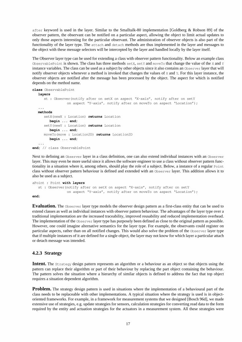
The Observer layer type can be used for extending a class with observer pattern functionality. Below an example classObservablePoint is shown. The class has three methodssetX , setY andmoveTo that change the value of theX andY
instance variables. The class can be used as a subject by other objects since it also contains anObserver layer that willnotify observer objects whenever a method is invoked that changes the values ofX andY. For this layer instance, theobserver objects are notified after the message has been processed by the object. The aspect for which is notifieddepends on the method name.
class ObservablePointlayers
st : Observer(notify after on setX on aspect “X-axis”, notify after on setYon aspect “Y-axis”, notify after on moveTo on aspect “Location”);
...methods
setX(newX : Location) returns Locationbegin ... end;
setY(newY : Location) returns Locationbegin ... end;
moveTo(move : Location2D) returns Location2Dbegin ... end;
...end; // class ObservablePoint
Next to defining anObserver layer in a class definition, one can also extend individual instances with anObserver
layer. This may even be more useful since it allows the software engineer to use a class without observer pattern func-tionality in a situation where it, among others, should play the role of a subject. Below, a instance of a regularPoint
class without observer pattern behaviour is defined and extended with anObserver layer. This addition allows it toalso be used as a subject.
aPoint : Point with layersst : Observer(notify after on setX on aspect “X-axis”, notify after on setY
on aspect “Y-axis”, notify after on moveTo on aspect “Location”);end;
Evaluation. TheObserver layer type models the observer design pattern as a first-class entity that can be used toextend classes as well as individual instances with observer pattern behaviour. The advantages of the layer type over atraditional implementation are the increased traceability, improved reusability and reduced implementation overhead.The implementation of theObserver layer type has purposely been defined as close to the original pattern as possible.However, one could imagine alternative semantics for the layer type. For example, the observants could register onparticular aspects, rather than on all notified changes. This would also solve the problem of theObserver layer typethat if multiple instances of it are defined for a single object, the layer may not know for which layer a particular attachor detach message was intended.
4.2.3 Strategy
Intent. The Strategy design pattern represents an algorithm or a behaviour as an object so that objects using thepattern can replace their algorithm or part of their behaviour by replacing the part object containing the behaviour.The pattern solves the situation where a hierarchy of similar objects is defined to address the fact that top objectrequires a situation dependent algorithm.
Problem. The strategy design pattern is used in situations where the implementation of a behavioural part of theclass needs to be replaceable with other implementations. A typical situation where the strategy is used is in object-oriented frameworks. For example, in a framework for measurement systems that we designed [Bosch 96d], we madeextensive use of strategies, e.g. update strategies for sensors, calculation strategies for converting read data to the formrequired by the entity and actuation strategies for the actuators in a measurement system. All these strategies were

18
characterised by the fact that they all were rather application dependent. The effect of using strategies was that someapplications could be developed from the framework solely by defining the appropriate, application dependent strate-gies. However, also the strategy pattern has some problems associated with its use. The first problem istraceabilitysince a strategy is implemented as a part object that is invoked by the object when the algorithm has to be executed.Without analysing the code, the software engineer cannot determine whether the part object is a regular part object, astrategy object or something else. Secondly, the strategy pattern suffers from theself problem, i.e. when the strategyobject refers toself, it addresses itself instead of the object containing the strategy. Since the strategy object in princi-ple implements one or more methods of the containing object, one would ideally just plug-in methods in the contain-ing object rather than implementing them in a separate object. Thirdly, there is implementation overhead since thecontaining object needs to forward client calls requiring the strategy to the strategy object. In addition, the softwareengineer, while defining the containing and strategy objects, needs to explicitly distinguish between calls to the objectitself and the strategy or containing object, respectively.
Figure 12. Structure of theStrategy pattern
Solution. When designing a solution within the context ofLayOM , one has two solution approaches. The first is todefine a delegating layer that delegates all messages to the strategy object to a strategy object that it contains, whereasthe second solution is to define a layer type that allows one to specify a method implementation as part of the layerconfiguration. The layer will then act as a method of the object that it encapsulates. However, as we decided to definethe layer types as close to the definition of the design patterns as possible, we adopted the former solution approach.
To address the problems described above, a layer typeStrategy was defined that delegates relevant messages to astrategy object that is contained inside the layer. The syntax of the layer type is as shown below. The strategy layerdelegates all matching messages to the strategy object. Whether a message matches depends on the layer configura-tion. If a list of messages is defined, a message has to match this set to be delegated. Otherwise, all messages matchingthe interface of the strategy object are delegated. On instantiation of the layer, the layer instantiates an instance ofclass<class> which represents the strategy object. However, the strategy object can be replaced if the ‘set by
<mess-sel> ’ part is present.
<id> : Strategy( delegate [<mess-sel>+| ] to <class> [set by <mess-sel>]);
A class can define one or more instances of the Strategy layer type to deal with its application dependent parts. Forexample, a class Sensor with an update and a calculation strategy could be defined as shown below. The sensor hastwo strategies, i.e. an update strategy and a calculation strategy. Both layers instantiate some default strategy class butallow for replacement with a new strategy by specifying the method for replacing the strategy object.
class Sensorlayers
update : Strategy( delegate to UpdateStrategy set by newUpdateStrategy);calculate : Strategy( delegate to CalculationStrategy set by newCalculationStrategy);
...end; // class Sensor
Evaluation. When evaluating theStrategy layer type with respect to the original design pattern specification, onecan identify that the strategy layer type implements the complete functionality of the pattern in an intuitive way. Inaddition, it solves the identified problems related to traceability, the self problem and the implementation overhead.Traceability is, obviously, improved since the layer type explicitly specifies what design pattern it implements. Due tothe delegating behaviour of a layer, i.e. the original receiver of the message is stored, the self problem does not occur.References toself in the strategy object are directed to the originally message receiving object. Similarly,self callsto methods implemented in the strategy object are intercepted by the layer and delegated to the strategy object.
Context
contextInterface()
Strategy
algorithmInterface()
ConcreteStrategyA
algorithmInterface()
ConcreteStrategyB
algorithmInterface()
ConcreteStrategyC
algorithmInterface()
strategy

19
Finally, the layer type requires only a minimal implementation effort from the software engineer. Only the relevantaspects need to be specified and no overhead due to message forwarding or otherwise occurs.
4.2.4 Mediator
Intent. The Mediator design pattern encapsulates the interaction of a set of objects. TheMediator decreases thecoupling between the objects since they do not refer to each other directly. TheMediator can be replaced independ-ently, allowing one to vary the interaction between the objects.
Problem. The implementation approach for theMediator design pattern is to decouple the functionality of anobject from its interaction with other objects. The interaction of a group of objects is encapsulated in a separate object,indicated as the Mediator. As shown in figure 13, a classMediator has a reference to each object in the set that itmediates. Each object in the set (Colleague ) has a reference to its mediator. Thus instead of sending a message to oneof its colleagues directly, it sends the message to theMediator that will forward the message to the appropriate object.
Although this approach separates the functionality of an object from its interaction with other objects and thus makingit more reusable and flexible, one can identify some problems in the implementation when using a traditional object-oriented language. First, theMediator consists of a set of methods that can be called by the colleague objects. Themethods, in general, only consist of a call to the colleague object that is supposed to take care of the message. This ismuch work, but it also leads to the second problem: The structure of the interactions between the objects is lost in theimplementation and can not be traced from design to implementation.
Figure 13. Structure of theMediator design pattern
Solution. As a solution, the layer typeMediator is proposed. TheMediator layer is part of a mediator class andcontains the specification of the interactions between the objects. The syntax of theMediator layer type is shownbelow.
<id> : Mediator( forward <mess-sel>+ from <client> to <object>,forward <mess-sel>+ from <client> to <object>, ... );
The semantics of theMediator layer is that a message in the<mess-sel>+ set of message selectors sent by a clientobject<client> is forwarded to an object<object> . The<client> specification is based on the client categories ofLayOM . The software engineer can specify a client category for each relevant subset of the interacting objects. Insteadof a defined client category, the keywordAny can be used matching all possible clients.
Below an example classConcreteMediator is shown. TheMediator layer forwards all messages with selectormessA
to object ConcreteColleague1 and all messagesmessB sent by objectConcreteColleague1 to objectConcreteColleague2 .
class ConcreteMediatorlayers
med : Mediator( forward messA from Any to ConcreteColleague1,forward messB from ConcreteColleage1 to ConcreteColleague2);
...end; // class ConcreteMediator
Evaluation. TheMediator layer type solves the identified problems. First, the software engineer does not have towrite a series of methods only for forwarding purposes. The specification of a single layer is sufficient. Secondly, thelayer specification shows very clearly the structure of the interaction between the objects. The traceability is thus pre-served.
Mediator Colleague
ConcreteColleague1 ConcreteColleague2ConcreteMediator

20
4.3 Composition
The design pattern layer types discussed in section 4.1 and 4.2 and several other layer types implementing design pat-tern or other abstractions are freely composable in class descriptions or instance declarations. Since layers based theirfunctioning on message interception and a message afterwards most often proceeds to its intended destination, a mes-sage can be intercepted by several layers. Thus, several layers can affect the contents of the message or implicitly trig-ger actions. For instance, a layer of typeAdapter and a layer of typeMediator can be composed in a classConcreteMediator . TheAdapter can change the selector of certain messages so that theMediator can forward themessage to colleague objects that otherwise could not have been in the same group due to incompatible interfaces.
This type of composability is important in object-oriented software development based on design patterns, such asobject-oriented framework development. Designers are increasingly making use of design patterns as design mecha-nisms and for describing designs to other software engineers. As a consequence, some classes in the design might playa role in two or more design patterns. The intertwining of the various patterns in the implementation of these classes ina traditional object-oriented language may result in rather complicated structures. The increased complexity and thepoor traceability of the individual design patterns obviously are important hindrances for effective use of design pat-terns. An implementation of these classes inLayOM does not suffer from these problems.
5 Related Work
[Soukup 95] is one of the few author that specifically addresses the implementation aspects of patterns. Soukup dis-cusses the implementation of design patterns and identified three problems. First, patterns often get lost during imple-mentation. Second, composed patterns can lead to large clusters of mutually dependent classes. Third, although designpattern authors present the classes that make up the implementation of the design patterns, no library of concretedesign pattern classes has been described. Soukup addresses this by implementing design patterns as C++ classes.When evaluating this approach, one can conclude that the traceability of design patterns in the implementation isimproved. However, only a few pattern classes are presented and we are uncertain whether all patterns can be imple-mented as classes. We consider several patterns, e.g. the patterns addressed in this paper, unsuited for representationas classes. A second aspect is that the implementation efficiency problems are not addressed by Soukup’s approach.
[Kim & Benner 95] discuss the implementation of the observer pattern. They identified that the observer pattern asproposed in [Gamma et al. 94] still leaves much room for implementation decissions. The authors propose severalimplementation patterns to address this issue, but they remain within the conventional object-oriented paradigm.
In [Budinsky et al. 96], a tool for automatic code generation from design patterns is described. The authors also iden-tified problems with the implementation of patterns, e.g. some designers have difficulty converting patterns into codeand most designers consider implementing a chore they would rather avoid. As a solution, a tool was developed thatallows the user to specify the application specific aspects of the pattern based on which the tool generates output codethat can be incorporated in the system. Although there are similarities between this approach and theLayOM model,e.g. both use a code generator for generating code in a conventional object-oriented language, the main difference isthat LayOM provides an integrated language model whereas the use of a tool not results in the same level of integra-tion. In addition, we are uncertain whether the traceability problem and the self problem have been addressed.
6 Conclusion
The problems associated with the implementation of design patterns in traditional object-oriented languages havebeen identified and discussed in this paper. These problems can be categorised into the lack of traceability of designpatterns in the implementation, the self problem that several pattern implementations suffer from, the lack of reusabil-ity of design pattern implementations and the implementation overhead for the software engineer when implementingdesign pattern.
A solution within the context of the layered object model has been introduced. The layered object model (LayOM) is anextended and extensible object model. It isextended because it containsstates, categories and layers as additionalcomponents.LayOM is anextensible object model because it can be extended with new components and new layertypes. In this paper, the identified problems were addressed by defining a layer type for a design pattern. Severaldesign patterns,i.e. Adapter , Bridge , Composite , Facade , State , Observer , Strategy andMediator , and the

21
associated layer types have been presented as examples of the applicability of our approach. We have illustrated thatthese layers do not suffer from the aforementioned problems.
We consider the layered object model a superior approach for practitioners, asLayOM is supported by an advancedimplementation environment that translatesLayOM classes and applications to C++ code. The generated C++ code canbe used in combination with arbitrary C++ programs to generate applications. Thus, the software engineer usingLayOM has the advantages of the extended expressiveness and avoids potential disadvantages as being limited to a par-ticular environment language because the environment generates C++ code.
A second advantage of the layered object model and its supporting environment, only briefly mentioned in this paper,is the extensibility of the object model. This allows the software engineer, among others, to define layer types fordesign patterns that were not available. One is able to extend the compiler relatively easy due to the fact that it is con-structed using the concept ofdelegating compiler objects.
As part of future work, we intend to study how design patterns from different sources will be incorporated in the lay-ered object model. Several authors have reported on application domain specific design patterns. The extensibility ofthe layered object model makes it very suitable to incorporate these design patterns.
Acknowledgements
Michael Mattsson and Petra Bosch provided valuable comments on earlier versions of this paper.
References
[Alexanderet al. 77]. C. Alexander, S. Ishikawa, M. Silverstein, M. Jacobson, I. Fiksdahl-King, S. Angel, ‘A PatternLanguage,’Oxford University Press, New York 1977.
[Bosch 95]. J. Bosch, ‘Layered Object Model - Investigating Paradigm Extensibility,’Ph.D. dissertation, Departmentof Computer Science, Lund University, November 1995.
[Bosch 96a]. J. Bosch, ‘Relations as Object Model Components,’Journal of Programming Languages, Vol. 4, pp. 39-61, 1996.
[Bosch 96b]. J. Bosch, ‘Abstracting Object State,’ accepted for publication inObject Oriented Systems, 1996.
[Bosch 96c]. J. Bosch, ‘Delegating Compiler Objects - An Object-Oriented Approach to Crafting Compilers,’Pro-ceedings Compiler Construction ‘96, pp. 326-340, 1996.
[Bosch 96d]. J. Bosch, ‘An Object-Oriented Framework for Measurement Systems,’Draft paper, University of Karl-skrona/Ronneby, October 1996.
[Budinskyet al.96]. F.J. Budinsky, M.A. Finnie, J.M. Vlissides, P.S. Yu, ‘Automatic code generation from design pat-terns,’IBM Systems Journal, Vol. 35, No. 2, 1996.
[Buschmann & Meunier 95]. F. Buschmann, R. Meunier, ‘A System of Patterns,’ inPattern Languages of ProgramDesign, J.O. Coplien, D.C. Schmidt (eds.), pp. 325-343, Addison-Wesley, 1995.
[Buschmannet al. 96]. F. Buschmann, C. Jäkel, R. Meunier, H. Rohnert, M.Stahl,Pattern-Oriented Software Archi-tecture - A System of Patterns, John Wiley & Sons, 1996.
[Coad 92]. P. Coad, ‘Object-Oriented Patterns,’Communications of the ACM, Vol. 35, No. 9, pp. 152-159, September1992.
[Coplien & Schmidt 95]. J.O. Coplien, D.C. Schmidt,Patterns Languages of Program Design, Addison-Wesley,1995.
[Foote & Yoder 95]. B. Foote, J. Yoder, ‘Evoluation, Architecture, and Metamorposis,’ in [Vlissideset al. 95]
[Gammaet al. 94]. E. Gamma, R. Helm, R. Johnson, J.O. Vlissides,Design Patterns - Elements of Reusable Object-Oriented Software, Addison-Wesley, 1994.
[Goldberg & Robson 89]. A. Goldberg, D. Robson,Smalltalk-80 - The Language, Addison-Wesley, 1989.
[Helm et al. 90]. R. Helm, I. Holland, D. Ganghopadhyay, ‘Contracts: Specifying Behavioral Compositions in Object-Oriented Systems,’OOPSLA ‘90, pp. 169-180, 1990.

22
[Kim & Benner 95]. J.J. Kim, K.M. Benner, ‘Implementation Patterns for the Observer Pattern,’ in [Vlissideset al.95].
[Lieberman 86]. H. Lieberman, ‘Using Prototypical Objects to Implement Shared Behavior in Object Oriented Sys-tems,’Proceedings OOPSLA ‘86, pp. 214-223, 1986.
[Mattsson 95]. M.M. Mattsson, ‘Object-Oriented Frameworks - a survey of methodological issues’,Licentiate thesis(in preparation), Department of Computer Science, Lund University, 1995.
[Pree 95]. W. Pree,Design Patterns for Object-Oriented Software Engineering, Addison-Wesley, 1995.
[Soukup 95]. J. Soukup, ‘Implementing Patterns,’ inPattern Languages of Program Design, J.O. Coplien, D.C.Schmidt (eds.), pp. 395-412, Addison-Wesley, 1995.
[Vlissideset al. 95]. J. Vlissides, J.O. Coplien, N.L. Kerth,Pattern Languages of Program Design 2, Addison-Wesley,1995.