Embed Size (px)
Citation preview
SEAOC 2011 CONVENTION PROCEEDINGS
1
Design Parameters for Steel Special Moment Frame Connections
Scott M. Adan, Ph.D., S.E., SECB, Chair
SEAONC Structural Steel Subcommittee Principal
Adan Engineering Oakland, California
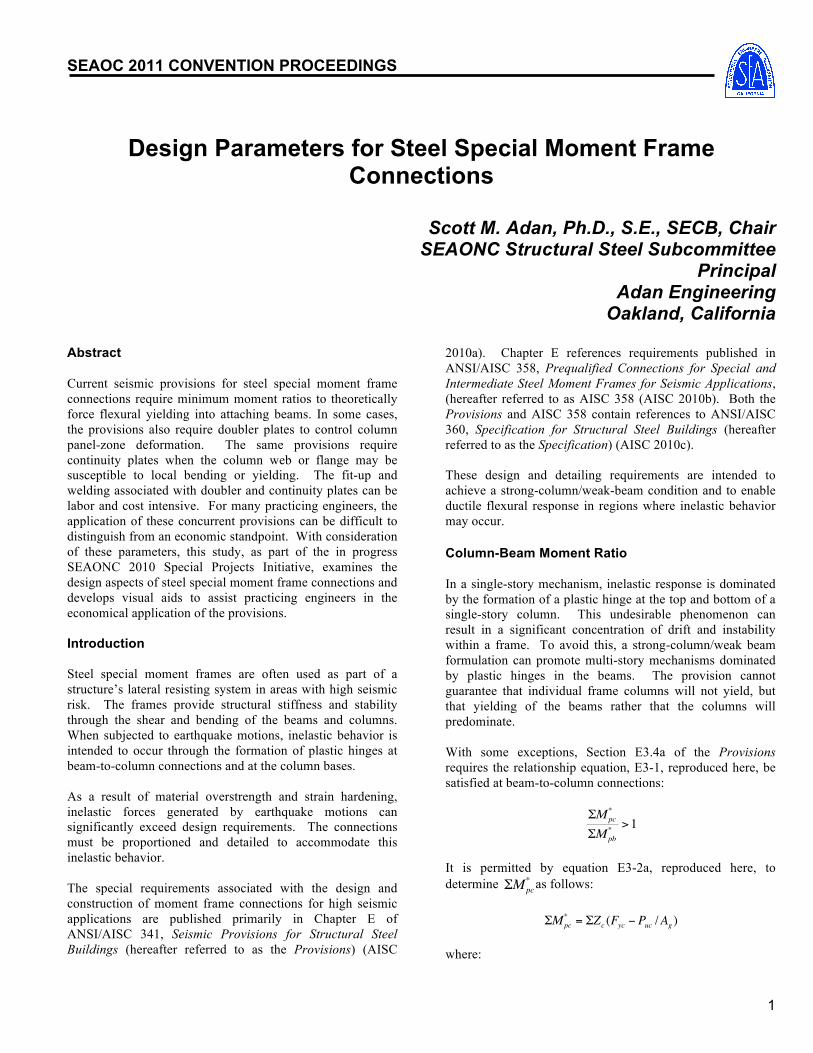
Abstract Current seismic provisions for steel special moment frame connections require minimum moment ratios to theoretically force flexural yielding into attaching beams. In some cases, the provisions also require doubler plates to control column panel-zone deformation. The same provisions require continuity plates when the column web or flange may be susceptible to local bending or yielding. The fit-up and welding associated with doubler and continuity plates can be labor and cost intensive. For many practicing engineers, the application of these concurrent provisions can be difficult to distinguish from an economic standpoint. With consideration of these parameters, this study, as part of the in progress SEAONC 2010 Special Projects Initiative, examines the design aspects of steel special moment frame connections and develops visual aids to assist practicing engineers in the economical application of the provisions. Introduction Steel special moment frames are often used as part of a structure’s lateral resisting system in areas with high seismic risk. The frames provide structural stiffness and stability through the shear and bending of the beams and columns. When subjected to earthquake motions, inelastic behavior is intended to occur through the formation of plastic hinges at beam-to-column connections and at the column bases. As a result of material overstrength and strain hardening, inelastic forces generated by earthquake motions can significantly exceed design requirements. The connections must be proportioned and detailed to accommodate this inelastic behavior. The special requirements associated with the design and construction of moment frame connections for high seismic applications are published primarily in Chapter E of ANSI/AISC 341, Seismic Provisions for Structural Steel Buildings (hereafter referred to as the Provisions) (AISC
2010a). Chapter E references requirements published in ANSI/AISC 358, Prequalified Connections for Special and Intermediate Steel Moment Frames for Seismic Applications, (hereafter referred to as AISC 358 (AISC 2010b). Both the Provisions and AISC 358 contain references to ANSI/AISC 360, Specification for Structural Steel Buildings (hereafter referred to as the Specification) (AISC 2010c). These design and detailing requirements are intended to achieve a strong-column/weak-beam condition and to enable ductile flexural response in regions where inelastic behavior may occur. Column-Beam Moment Ratio In a single-story mechanism, inelastic response is dominated by the formation of a plastic hinge at the top and bottom of a single-story column. This undesirable phenomenon can result in a significant concentration of drift and instability within a frame. To avoid this, a strong-column/weak beam formulation can promote multi-story mechanisms dominated by plastic hinges in the beams. The provision cannot guarantee that individual frame columns will not yield, but that yielding of the beams rather that the columns will predominate. With some exceptions, Section E3.4a of the Provisions requires the relationship equation, E3-1, reproduced here, be satisfied at beam-to-column connections:
€
ΣMpc*
ΣMpb* >1
It is permitted by equation E3-2a, reproduced here, to determine
€
ΣMpc* as follows:
€
ΣMpc* = ΣZc (Fyc − Puc /Ag )
where:

2
Zc = plastic section modulus of the column, in.3 Fyc = Fy of the column, ksi Puc = required compressive strength using LRFD load
combinations, kips (a positive number) Ag = gross area of the column, in.2 It is also permitted by equation E3-3a, reproduced here, to determine
€
ΣMpb* as follows:
€
ΣMpb* = Σ(1.1RyFybZb + Muv )
where: Ry = ratio of the expected yield stress to the specified
minimum yield stress, Fy (per Table A3.1 of the Provisions)
Fyb = Fy of the beam, ksi Zb = plastic section modulus of the beam, in.3 The equation to determine the additional moment due to shear amplification from the location of the plastic hinge to the column centerline can be expressed as follows: ΣMuv = (Vh+Vh′)(dc/2+Sh) (1) where: dc = column depth, in. Sh = distance from the column face to the plastic hinge, in. The equations to determine the larger and smaller values of shear force at the plastic hinge can be expressed as follows: Vh = 2[1.1RyMp]/Lh+ wuLh/2 (2) Vh′= 2[1.1RyMp]/Lh – wuLh/2 (3) Where: Mp = FyZ = nominal plastic flexural strength, kip-in. Lh = distance between plastic hinges, in. wu = uniform beam gravity load, kips per linear ft. Doubler Plates At the connection to a beam, the column panel-zone must have adequate thickness to prevent excessive distortion or shear buckling. If the thickness is insufficient, the panel-zone can be strengthened with the addition of a doubler plate. As defined by Section E3.6e.(1) of the Provisions, the required shear strength of the panel-zone is determined from
the summation of the moments at the column faces as determined by projecting the expected moments at the plastic hinge points to the column faces as follows:
€
Ru =ΣMf
db−Vcol
(4)
where: db = beam depth, in. The equation to determine the larger and smaller values of the expected moment at the face of the column can be expressed as follows: Mf = 1.1RyMp + VhSh (4) Mf ′= 1.1RyMp + Vh′ Sh (5) The equation to determine the column shear can be expressed as follows:
€
Vcol =ΣMf
h (6)
where: h = average story height above and below the joint, in. In most instances, the nominal panel-zone shear strength, is determined by Equation J10-11, reproduced here, of Section J10.6 of the Specification:
€
φvRn = 0.60Fydctw 1+3bcf tcf
2
dbdctw
For Puc
€
≤ 0.75 Pc where: φv =1.0 per Section E3.6e(1) of the Provisions dc = column depth, in. tw = column web thickness, in. bcf = column flange width, in. tcf = column flange thickness, in. Pc =FyA, axial yield strength of the column, kips To identify the plastic panel-zone deformation contribution to the shear strength, Equation J10-11 can be written as: φvRn = 0.6Fy dctwVpz (7)
3
where:
€
Vpz = 1+3bcf tcf
2
dbdctw
(8)
The individual thickness of the column web and/or doubler plates, if required, is determined by Equation E3-7, reproduced here, of Section E3.63.(2) of the Provisions:
t ≥ (dz + wz)/90 where: t = thickness of column web or doubler plate, in. dz = depth of the panel-zone between beam flanges, in. wz = width of panel-zone between column flanges, in. With some exceptions Equation E3-7 can be written as: t ≥ [(db-2tbf )+ (dc-2tcf)]/90 (9) Continuity Plates At the connection to a beam, the column flange must be sufficiently rigid to prevent deformation or local bending. The column web must also be sufficiently rigid to prevent local yielding due to the corresponding high state of stress concentrations. The installation of stiffeners or continuity plates can address these local limit states. If the flange and web thicknesses are sufficient, the concentrated beam flange forces can be adequately transferred without the required stiffening effects or secondary load path. Section E3.6f of the Provisions requires continuity plates unless the column flange thickness satisfies equations E3-8 and E3-9, reproduced here:
€
tcf ≤ 0.4 1.8bbf tbfFybRyb
FycRyc
€
tcf ≥bcf6
where: bbf = beam flange width, in. tbf = beam flange thickness, in. tcf = minimum required thickness of column flange when no
continuity plates are provided, in. Fyc = Fy of the column, ksi Ryb = Ry of the beam (per Table A3.1 of the Provisions) Ryc = Ry of the column (per Table A3.1 of the Provisions)
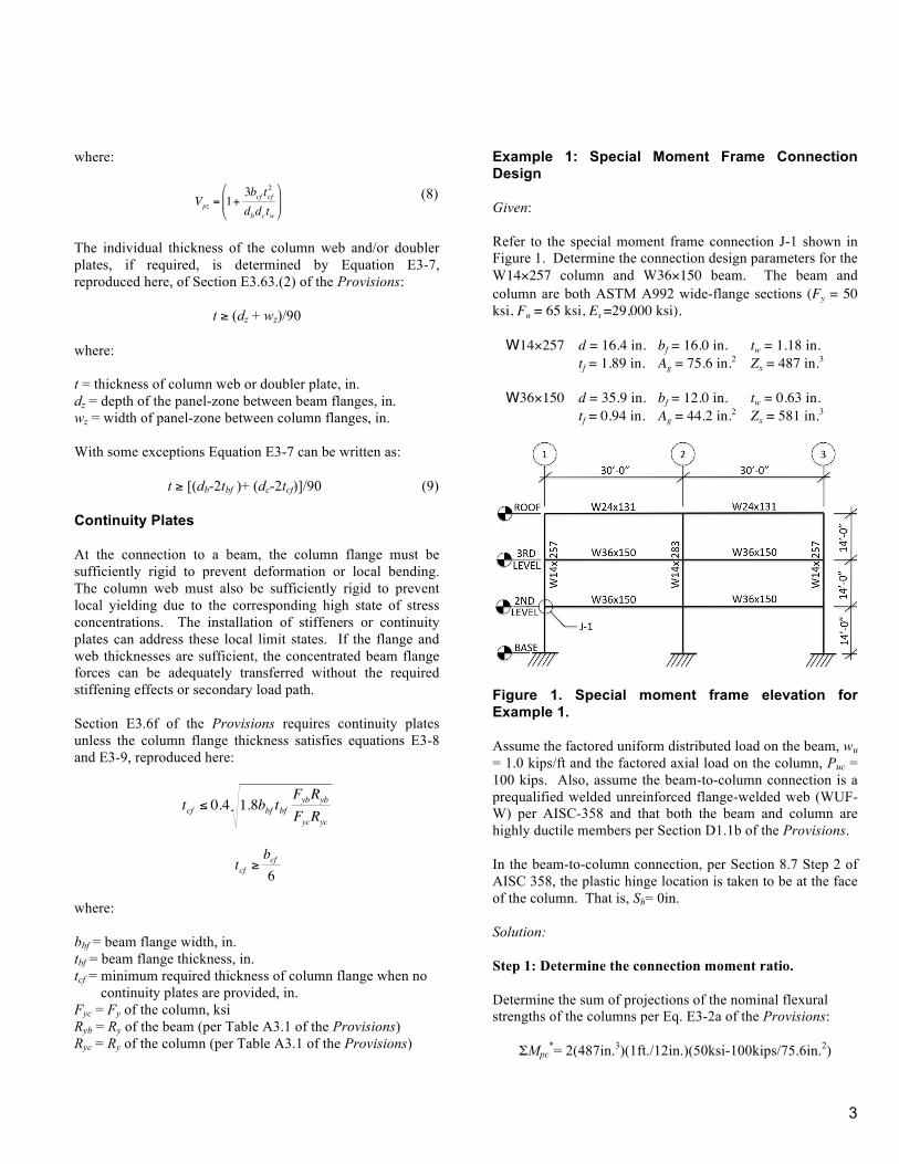
Example 1: Special Moment Frame Connection Design Given: Refer to the special moment frame connection J-1 shown in Figure 1. Determine the connection design parameters for the W14×257 column and W36×150 beam. The beam and column are both ASTM A992 wide-flange sections (Fy = 50 ksi, Fu = 65 ksi, Es =29,000 ksi). W14×257 d = 16.4 in. bf = 16.0 in. tw = 1.18 in. tf = 1.89 in. Ag = 75.6 in.2 Zx = 487 in.3 W36×150 d = 35.9 in. bf = 12.0 in. tw = 0.63 in. tf = 0.94 in. Ag = 44.2 in.2 Zx = 581 in.3
Figure 1. Special moment frame elevation for Example 1. Assume the factored uniform distributed load on the beam, wu = 1.0 kips/ft and the factored axial load on the column, Puc = 100 kips. Also, assume the beam-to-column connection is a prequalified welded unreinforced flange-welded web (WUF-W) per AISC-358 and that both the beam and column are highly ductile members per Section D1.1b of the Provisions. In the beam-to-column connection, per Section 8.7 Step 2 of AISC 358, the plastic hinge location is taken to be at the face of the column. That is, Sh= 0in. Solution: Step 1: Determine the connection moment ratio. Determine the sum of projections of the nominal flexural strengths of the columns per Eq. E3-2a of the Provisions:
ΣMpc*= 2(487in.3)(1ft./12in.)(50ksi-100kips/75.6in.2)

4
ΣMpc
*= 3951kip-ft. Determine the distance between plastic hinges, Lh′:
Lh′= 30ft.-16.4in.(1ft./12in.) = 28.6ft. Determine the expected shear force at the plastic hinge using Eq. (2):
Vh = 2[1.1(1.1)(50ksi)(581in.3)(1ft./12in.)/(28.6ft.)] +1.0 kip/ft.(28.6ft.)/2 Vh = 218.9kips
Because the connection is single sided, Vh ′= 0 kips. Determine the additional moment due to shear amplification from the location of the plastic hinge to the column centerline using Eq. (1):
ΣMuv = (218.9kips)(16.4in.)(1ft./12in.)/2) = 149.6kip-ft. Determine the sum of the projections of the expected flexural strength of the beam per Eq. E3-3a of the Provisions:
ΣMpb*=(1.1)(1.1)(50ksi)(581in. 3)(1ft./12in.)+149.6kip-ft.
ΣMpb
*= 3079kip-ft. Determine the moment ratio of the connection per Eq. E3-1 of the Provisions:
3051kip-ft./3079kip-ft.=1.3 > 1.0 o.k. Step 2: Determine if a doubler plate is required. Determine the expected moment at the face of the column using Eq. (4):
Mf = 1.1(1.1)(50ksi)(581in.3)(1ft./12in.) = 2929kip-ft. Determine the column shear using Eq. (6):
€
Vcol =2(2929kip− ft.)
2(14 ft.)= 209kips
Determine the required panel-zone shear strength using Eq. (4):
€
Ru =2929kip− ft.
35.9in.(1 ft./12in.)− 209kips = 770kips
Check that the required column axial compressive strength is less than or equal to the axial yield strength per Eq. J10-11 of the Specification:
Puc
€
≤ 0.75(50ksi)(75.6) = 2835kips o.k. Therefore, determine the plastic panel-zone deformation contribution to the shear strength using Eq. (8):
€
Vpz = 1+3(16in.)(1.89in.)2
(35.9in.)(16.4in.)(1.18in.)
=1.25
Determine the nominal panel-zone shear strength of the column using Eq. (7):
φvRn = 0.60(50ksi)(16.4in.)(1.18in.)(1.25) φvRn = 726kips < 770kips n.g.
Therefore, determine the required panel-zone thickness, tpz, using the following equation: tpz ≥ tcwRu/φvRn (10)
tpz ≥ (1.18in.)(770kips)/(1.0)(726kips) = 1.25in. Determine the required doubler plate thickness, tdp, using Eq. (9):
tdp ≥ {[35.9in.-2(0.94in.)]+ [16.4in.-2(1.18in.)]}/90
tdp ≥ 0.53in. Therefore, try a 5/8 in. doubler plate, tdp = 0.63in., and check if the doubler plate provides adequate panel-zone thickness using the following equation: tcw+ tdp ≥ tpz (11)
1.18in.+ 0.63in.= 1.81in. > 1.25in. o.k. Therefore, a 5/8 in. doubler plate is adequate.
Step 3: Determine if a continuity plate need not be provided. Determine if the thickness of the column flange satisfies Eqs. E3-8 and E3-9 of the Provisions:
€
tcf ≤ 0.4 1.8(12.0in.)(0.94in.) 50ksi(1.1)50ksi(1.1)
5
= 1.80in. < 1.89in. o.k.
€
tcf ≥12.0in.6
=2.0in. > 1.89in. n.g.
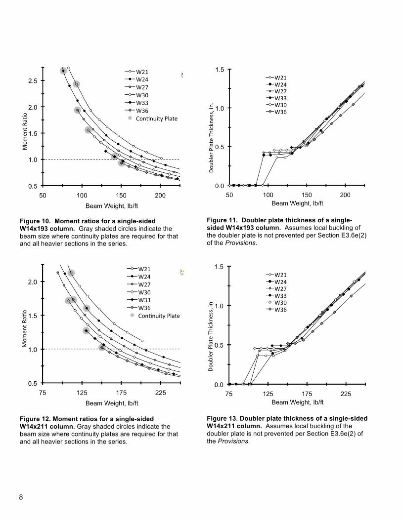
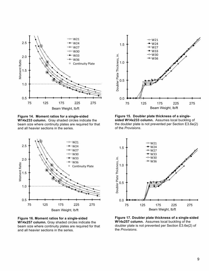
Therefore, continuity plates must be provided. Visual Aids With consideration of the calculated parameters associated with moment ratios, doubler, and continuity plates, visual representations of the requirements for most highly ductile single-sided W14 columns are presented herein. The visual aids are shown in Figures 2 through 25. In the even numbered figures, the moment ratios and continuity plate requirements are displayed. In the odd numbered figures, the required double plate thicknesses are displayed. The specific beam-to-column connection design parameters associated with Example 1 are displayed in Figures 16 and 17. The figures are limited to multi-story connections (column above and below the joint) and were developed with the assumptions indicated in Example 1, including the following:
• Beam span =30ft. • Average column height =14ft. • Factored uniform beam load = 1kip/ft. • Factored axial column load = 100kips • Plastic hinge location at the column face. • Beam flanges not reduced.
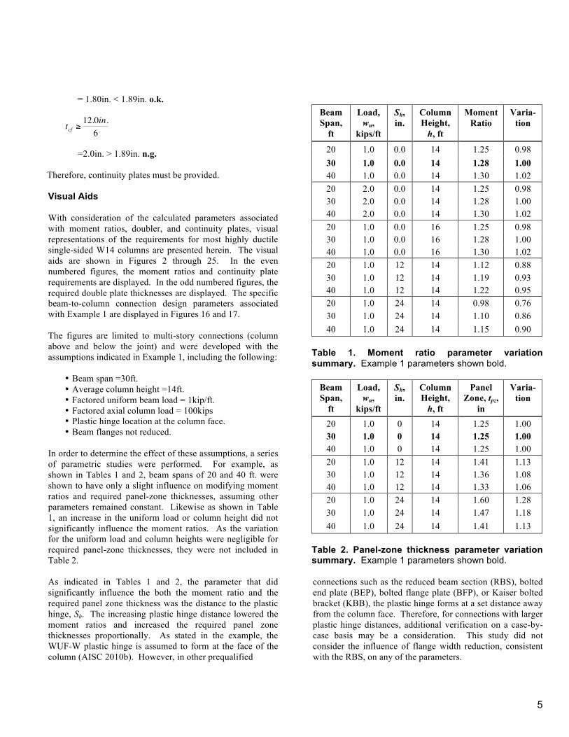
In order to determine the effect of these assumptions, a series of parametric studies were performed. For example, as shown in Tables 1 and 2, beam spans of 20 and 40 ft. were shown to have only a slight influence on modifying moment ratios and required panel-zone thicknesses, assuming other parameters remained constant. Likewise as shown in Table 1, an increase in the uniform load or column height did not significantly influence the moment ratios. As the variation for the uniform load and column heights were negligible for required panel-zone thicknesses, they were not included in Table 2. As indicated in Tables 1 and 2, the parameter that did significantly influence the both the moment ratio and the required panel zone thickness was the distance to the plastic hinge, Sh. The increasing plastic hinge distance lowered the moment ratios and increased the required panel zone thicknesses proportionally. As stated in the example, the WUF-W plastic hinge is assumed to form at the face of the column (AISC 2010b). However, in other prequalified
Beam Span,
ft
Load, wu,
kips/ft
Sh, in.
Column Height, h, ft
Moment Ratio
Varia-tion
20 1.0 0.0 14 1.25 0.98 30 1.0 0.0 14 1.28 1.00 40 1.0 0.0 14 1.30 1.02 20 2.0 0.0 14 1.25 0.98 30 2.0 0.0 14 1.28 1.00 40 2.0 0.0 14 1.30 1.02 20 1.0 0.0 16 1.25 0.98 30 1.0 0.0 16 1.28 1.00 40 1.0 0.0 16 1.30 1.02 20 1.0 12 14 1.12 0.88 30 1.0 12 14 1.19 0.93 40 1.0 12 14 1.22 0.95 20 1.0 24 14 0.98 0.76 30 1.0 24 14 1.10 0.86 40 1.0 24 14 1.15 0.90
Table 1. Moment ratio parameter variation summary. Example 1 parameters shown bold.
Beam Span,
ft
Load, wu,
kips/ft
Sh, in.
Column Height, h, ft
Panel Zone, tpz,
in
Varia-tion
20 1.0 0 14 1.25 1.00 30 1.0 0 14 1.25 1.00 40 1.0 0 14 1.25 1.00 20 1.0 12 14 1.41 1.13 30 1.0 12 14 1.36 1.08 40 1.0 12 14 1.33 1.06 20 1.0 24 14 1.60 1.28 30 1.0 24 14 1.47 1.18 40 1.0 24 14 1.41 1.13
Table 2. Panel-zone thickness parameter variation summary. Example 1 parameters shown bold. connections such as the reduced beam section (RBS), bolted end plate (BEP), bolted flange plate (BFP), or Kaiser bolted bracket (KBB), the plastic hinge forms at a set distance away from the column face. Therefore, for connections with larger plastic hinge distances, additional verification on a case-by-case basis may be a consideration. This study did not consider the influence of flange width reduction, consistent with the RBS, on any of the parameters.

6
Figure 2. Moment ratios for a single-sided W14x132 column. Gray shaded circles indicate the beam size where continuity plates are required for that and all heavier sections in the series.
Figure 4. Moment ratios for a single-sided W14x145 column. Gray shaded circles indicate the beam size where continuity plates are required for that and all heavier sections in the series.
Figure 3. Doubler plate thickness of a single-sided W14x132 column. Assumes local buckling of the doubler plate is not prevented per Section E3.6e(2) of the Provisions.
Figure 5. Doubler plate thickness of a single-sided W14x145 column. Assumes local buckling of the doubler plate is not prevented per Section E3.6e(2) of the Provisions.
7
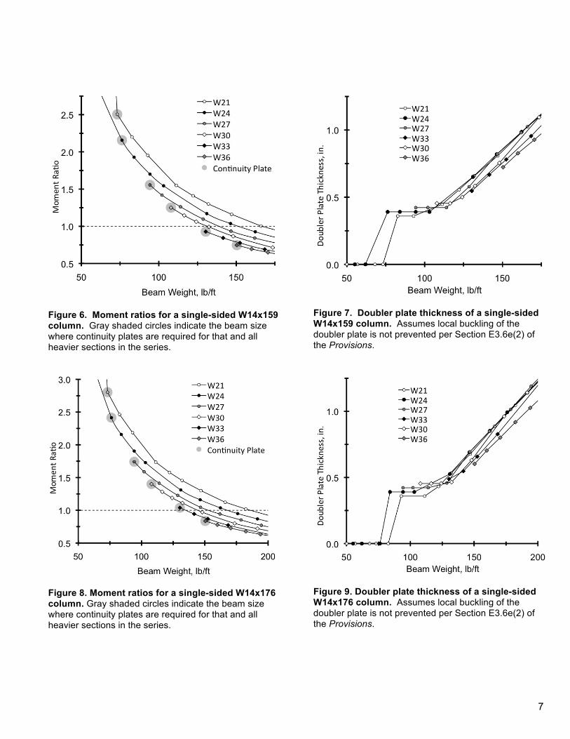
Figure 6. Moment ratios for a single-sided W14x159 column. Gray shaded circles indicate the beam size where continuity plates are required for that and all heavier sections in the series.
Figure 8. Moment ratios for a single-sided W14x176 column. Gray shaded circles indicate the beam size where continuity plates are required for that and all heavier sections in the series.
Figure 7. Doubler plate thickness of a single-sided W14x159 column. Assumes local buckling of the doubler plate is not prevented per Section E3.6e(2) of the Provisions.
Figure 9. Doubler plate thickness of a single-sided W14x176 column. Assumes local buckling of the doubler plate is not prevented per Section E3.6e(2) of the Provisions.
8
Figure 10. Moment ratios for a single-sided W14x193 column. Gray shaded circles indicate the beam size where continuity plates are required for that and all heavier sections in the series.
Figure 12. Moment ratios for a single-sided W14x211 column. Gray shaded circles indicate the beam size where continuity plates are required for that and all heavier sections in the series.
Figure 11. Doubler plate thickness of a single-sided W14x193 column. Assumes local buckling of the doubler plate is not prevented per Section E3.6e(2) of the Provisions.
Figure 13. Doubler plate thickness of a single-sided W14x211 column. Assumes local buckling of the doubler plate is not prevented per Section E3.6e(2) of the Provisions.
9
Figure 14. Moment ratios for a single-sided W14x233 column. Gray shaded circles indicate the beam size where continuity plates are required for that and all heavier sections in the series.
Figure 16. Moment ratios for a single-sided W14x257 column. Gray shaded circles indicate the beam size where continuity plates are required for that and all heavier sections in the series.
Figure 15. Doubler plate thickness of a single-sided W14x233 column. Assumes local buckling of the doubler plate is not prevented per Section E3.6e(2) of the Provisions.
Figure 17. Doubler plate thickness of a single-sided W14x257 column. Assumes local buckling of the doubler plate is not prevented per Section E3.6e(2) of the Provisions.

10
Figure 18. Moment ratios for a single-sided W14x283 column. Gray shaded circles indicate the beam size where continuity plates are required for that and all heavier sections in the series.
Figure 20. Moment ratios for a single-sided W14x311 column. Gray shaded circles indicate the beam size where continuity plates are required for that and all heavier sections in the series.
Figure 19. Doubler plate thickness of a single-sided W14x283 column. Assumes local buckling of the doubler plate is not prevented per Section E3.6e(2) of the Provisions.
Figure 21. Doubler plate thickness of a single-sided W14x311 column. Assumes local buckling of the doubler plate is not prevented per Section E3.6e(2) of the Provisions.
11
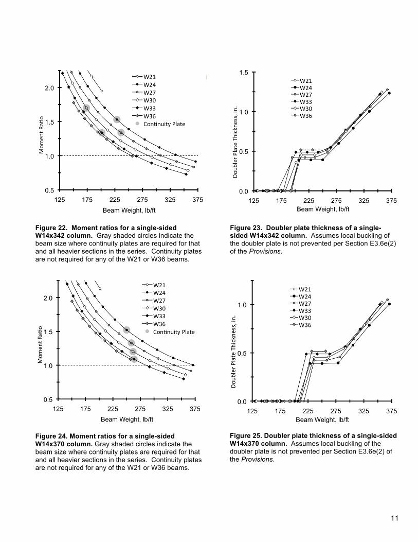
Figure 22. Moment ratios for a single-sided W14x342 column. Gray shaded circles indicate the beam size where continuity plates are required for that and all heavier sections in the series. Continuity plates are not required for any of the W21 or W36 beams.
Figure 24. Moment ratios for a single-sided W14x370 column. Gray shaded circles indicate the beam size where continuity plates are required for that and all heavier sections in the series. Continuity plates are not required for any of the W21 or W36 beams.
Figure 23. Doubler plate thickness of a single-sided W14x342 column. Assumes local buckling of the doubler plate is not prevented per Section E3.6e(2) of the Provisions.
Figure 25. Doubler plate thickness of a single-sided W14x370 column. Assumes local buckling of the doubler plate is not prevented per Section E3.6e(2) of the Provisions.

12
In general, the continuity plate requirements are not influenced by the assumed parameters. Therefore, the effects they may have on the associated requirements were not considered. Summary and Conclusions A study was performed to consider parameters associated with steel special moment frame connection design. The parameters include moment ratios to promote strong-column/weak-beam mechanisms, doubler plates to control panel-zone deformation, and continuity plates to address local flange bending or web yielding. The corresponding code design provisions were reviewed and an example was illustrated. The example included the design of a typical moment frame single-sided beam-to-column connection. To further illustrate the provisions, a series of visual aids were developed. The visual aids provide a means to distinguish the concurrent provisions from an economic standpoint in that the elimination of doubler or continuity plates can often provide significant cost savings in steel fabrication. The development of the visual aids required a number of assumptions with respect to beam spans, column heights, loading, and connection configuration. As part of the study, these parameters were examined independently to understanding their influence on the overall design provisions. In general, the visual aids provide reasonable design estimations when it is assumed the beam plastic hinge occurs at or near the column face. When the plastic hinge occurs away from column face, the aids can still provide a reasonable estimation, but further verification is also recommended. The limit on paper length in these proceedings precludes further development of the visual aids, particularly with respect to double-sided connections or deep section columns. Those further aids, currently under development, will the focus of a future supplemental paper. Acknowledgements The Structural Engineers Association of Northern California (SEAONC), as part of the 2010 Special Projects Initiative provided funding for this project. While endeavoring to provide practical and accurate information in this publication, neither SEAONC including its board, committees, and members nor the author, assume liability for, nor make any expressed or implied warranty with regard to, the use of its
information. Users of the information in this publication assume all liability arising from such use. References AISC, 2010a, AISC/ANSI 341-10 – Seismic Provisions for Structural Steel Buildings, 2010, American Institute of Steel Construction (AISC), Chicago, Illinois. AISC, 2010b, AISC/ANSI 358-10 – Prequalified Connections for Special and Intermediate Steel Moment Frames for Seismic Applications, 2010, AISC, Chicago, Illinois. AISC, 2010c, AISC/ANSI 360-10 – Specification for Structural Steel Buildings, 2010, AISC, Chicago, Illinois.


![Design Parameters[1]](https://img.dokumen.tips/doc/110x75/577cd72f1a28ab9e789e492f/design-parameters1.jpg)