Embed Size (px)
Citation preview

Howard Torode
Member of General Aviation Group
and
Chairman BGA Technical Committee
Efficient Light Aircraft Design – Options from
Gliding

Presentation Aims• Recognise the convergence of interest
between ultra-lights and sailplanes
• Draw on experiences of sailplane
designers in pursuit of higher
aerodynamic performance.
• Review several feature of current
sailplanes that might be of wider use.
• Review the future for the recreational
aeroplane.

Lift occurs in localised areas
A glider needs efficiency and manoeuvrability


ASW-27
Glider (total) drag polar
Drag at low speed dominated byInduced drag (due to lift)
Drag at high speeds dominated by profile drag & skin friction
Drag contributions for a glider

So what are the configuration parameters?
- Low profile drag: Wing section design is key
- Low skin friction: maximise laminar areas
- Low induced drag – higher efficiencies demand greater spans, span efficiency and Aspect Ratio
- Low parasitic drag – reduce excrescences such as: undercarriage, discontinuities of line and no leaks/gaps.
- Low trim drag – small tails with efficient surface coupled with low stability for frequent speed changing.
- Wide load carrying capacity in terms of pilot weight and water ballast

1937: Wiehe (18m)
1957: Phoenix (16m)
1971: Nimbus 2 (20.3m) 2003: Eta (30.8m) 2010: Concordia (28m)
Wooden glidersMetal glidersComposite gliders
Progress in aerodynamic efficiency
1933 - 2010

In praise of Aspect Ratio• Basic drag equation in in non-dimensional, coefficient terms:
• For an aircraft of a given scale, aspect ratio is the single
overall configuration parameter that has direct leverage on
performance. Induced drag - the primary contribution to drag
at low speed, is inversely proportional to aspect ratio
• An efficient wing is a key driver in optimising favourable
design trades in other aspects of performance such as wing
loading and cruise performance.
• Aspect ratio also raises vehicle overall lift curve slope
providing a responsive, controllable aircraft.

Refinement of sailplane wing planforms
1922-1934
Images courtesy of Vince Cockett - scale soaring UK

Efficiency of load distribution for wings of AR=15
Induced drag additional to the ‘elliptic perfection’ of k =1

Aspect ratio – additional complexity?• Higher stresses (eg. Root BM)
– Leads to greater weight.
– Limited volume for Undercarriage & fuel.
• Aero-elasticity issues (requiring analysis).
– Torsional stiffness and control mass balance
• Control issues
– Higher roll inertia
– Roll control power and longer control runs
• Lower Reynolds numbers (at tip)
• Practical issues of space
– In workshop and hanger
– Need for transport joints?

Aero-elasticity
and Flutter
• Vibrations can take many forms but most modes are
'soft' (but usually graphically reported!)
• Aero-elastic analysis is a key task in design. The
only organisations fully capable are GE universities.
• The key parameter is adequate wing torsion rigidity,
which, when coupled with control mass balancing
can usually avoid interactions with bending or control
surface modes

In flight demonstration of aileron
induced flutter on a sailplane

Laminar aerofoils
The key to modern sailplane performance
FX 79-K-144 -17
NACA 63-418
FX 61-184

● These a simple, centre-hinged flaps, for performance
optimisation in fast and slow flight. They move DOWN AND UP
and are often mixed in functions with aileron control.
● They are NOT normally designed for high lift. Split, Fowler,
ventilated and high lift flaps are TOO DRAGGY for sailplanes
• Flap configuration can influence or limit lateral control in high
lift configuration particularly if mixed with aileron function.
Glider Performance Flaps

Relevance of thickness to sailplane wing
sections 20%
15%
10%
5%
Drag
Opera
ting S
peed R
ange
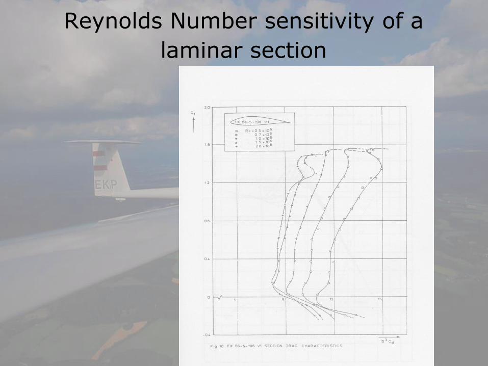
Reynolds Number sensitivity of a
laminar section

Reynolds Number sensitivity of a
laminar section
•A cross plot against
‘flight Re’ demonstrates
a reduction of
aerodynamic
performance as
airspeed and Re
reduces.
•This can be accounted
as an additional term in
‘lift dependent drag’
•This effect become
more significant as
chord reduces

Boermans T12 aerofoil
characteristics

Construction of a higher aspect ratio
wing in wood – finish standard required

A successful ‘mixed materials’ approach to
constructing a high aspect ratio, laminar
wing using small-scale, simple moulds

Basic shell structure of a Composite Sailplane – Slingsby/Glasflugel Kestrel

Homebuilding in GRP?

Metal structure solution –HP14

Winglet Design

Current winglet designs

Fuselage design – semi empirical approach

Corner vortex and effect on wing and fuselage flows

Fuselage design – extent of laminar flow

Wing to fuselage junction design
For the first half metre of the wing the wing section is tailored to a
‘turbulent ‘ style section to accommodate better the stream-wise
gradients and span-wise cross-flows that precipitate transition.

Wing to fuselage design – practical details
•Tailored wing section
at root
•Contraction behind &
above leading edge
•All junctions and
hatches sealed
•Very limited contour
filleting

Tailplane to fin junction design (1)
Tailplane
max
thickness
well ahead of
that of the fin
Separated and
sealed control
surface slots with
internal
mechanisms
Narrow
chord
elevator and
high aspect
ratio
tailplane

Electric propulsion – Antares 20E
• 42kW (56hp) brushless DC motor• 72 Li-ion batteries, 41Ah capacity, 76kg• 52hp for 13 minutes

Typical Jet installation

Front
Electric
Sustainer

Convergence of interest between powered sailplane and microlight?
- Smaller number of high cost, very high performance
gliders
- Emergence of cheaper self-launching (probably
electrically powered) motor gliders offers
- autonomous operation
- low operating cost and group ownership

Recreational
Cross Country
out of Lasham
by an electric
sustainer
sailplane

Typical height profile

Lines of energy in the
atmosphere

What the future holds?- Micro-light and lighter GA aircraft are
converging on the same design space.
- Limited endurance remains an issue at least for electric power in the short term.
- High efficiency design enables greater use of available energy in the atmosphere

• To harvest and store atmospheric energy one does not
have to stop for thermals, BUT a flightpath strategy
involving exchange of speed and height is required.
• The more efficient your airframe the easier this process
becomes.
• Critically, a track must be chosen to maximise transit
through areas of ‘good air’.
• While this process is weather dependent this should
not constrain your recreational enjoyment. Indeed the
satisfaction level should be enhanced.
• Piloting and airmanship, including lookout, must be
sufficiently good to accommodate the necessary changes
in heading and altitude, while complying with rules of the
air in uncontrolled airspace.
•There is an emerging need to adapt response, handling
and instrumentation to maximise pilot awareness
GUIDE TO LOW LOSS RECREATIONAL AVIATION


Questions ? – Discuss ?


![7 3 Sailplane GP-1 [Mode de compatibilité]...Sailplane Grand Prix 2014 World Sailplane Grand Prix Final 2014-2015 Qualifying Sailplane Grand Prix series 2015 World Sailplane Grand](https://img.dokumen.tips/doc/110x75/6023534700029d297b3d533e/7-3-sailplane-gp-1-mode-de-compatibilit-sailplane-grand-prix-2014-world.jpg)