Embed Size (px)
Citation preview

October 2017, Volume 4, Issue 10 JETIR (ISSN-2349-5162)
JETIR1710055 Journal of Emerging Technologies and Innovative Research (JETIR) www.jetir.org 332
Design of PV- based Impedance Source Inverter fed
Squirrel Cage Induction Motor Drive Suhashini Shinde*1
*1Department of Electrical Engineering, C.U.K-585367, Karnataka, India
Abstract— This paper presents a MATLAB / Simulink based design and performance of photo voltaic (PV) - based Impedance (Z)-source
inverter (ZSI) fed Squirrel Cage Induction Motor (SCIM) drive. In this work, with the implementation of Z link to the PV-source system, there
is no requirement of additional maximum power point tracking (MPPT) unit. The parameters of Z-source inverter are determined for boost
control method for a fixed modulation index. A simple MOSFET/Diode based universal bridge has considered as inverter along with the
impedance (Z) link of the ZSI. Performance of PV based ZSI is verified by connecting a constant speed squirrel cage induction motor drive
as a load.
Index Terms— Photo voltaic (PV), impedance source inverter (ZSI), maximum power point tracking (MPPT), total harmonics
reduction (THD), Squirrel Cage Induction Motor (SCIM), torque, speed.
________________________________________________________________________________________________________
I. INTRODUCTION
Among the renewable energy sources, photovoltaic (PV) systems are more popular because of simplicity in installation, easy
maintenance, noiseless, eco-friendly etc… Due to low cost of renewable energy sources, PV systems have given a lot of importance
in many applications [1].
One of the recent developed inverter topologies is Impedance (Z) source inverter (ZSI). The ZSI is very advantageous over
traditional inverters and it can be adapted for both in all ac and dc power conversion applications. [2]-[3]. Advantages of ZSIs in
electrical applications have given in literature [4],[5]. For boosting the dc link voltage of ZSI utilizes shoot through state. The r.m.s
value of output fundamental component of line voltage of ZSI can be expressed by given equations (1)-(3)[7]-[9]
𝑉𝑟𝑚𝑠 = 0.612 𝑀𝐵𝑉𝑑𝑐 (1)
Boost factor is a function of M is given by
𝐵 =1
2 𝑀− 1 (2)
And Modulation index (M) is given by
𝑀 = 1 − 𝐷 (3)
Where “D” is the shoot through ratio.
Shoot through is employed by comparing dc reference line signal with sinusoidal signal. Maximum possible value of shoot
through ratio, D of boost control is limited to (1-M). Hence for lower value of M, shoot through ratio is high which results in
degradation of spectral performance and vice-versa. In series ZSI, LC-network and Inverter Bridge both are in series manner. This
series combination is connected across dc source, which shows the reduced voltage across both capacitors [7]-[9].
Rest of the paper is organized as fallows. In introduction, importance of renewable energy based systems, PV systems
feasibilities, ZSI and its advantages, designing factors are briefly discussed. Proposed PV- based ZSI fed squirrel cage induction
motor drive system design and modelling in MATLB/Simulink gui environment are given in section. II Simulation results and
discussion are given in section.III. Finally conclusion and future scope of the proposed system is given in section. IV.
II. MODELLING AND DESIGN OF PROPOSED PV-BASED ZSI FED SQUIRREL CAGE INDUCTION MOTOR DRIVE SYSTEM
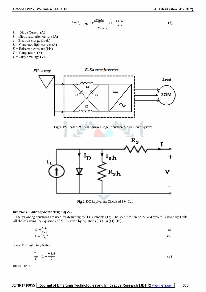
Fig.1. shows the proposed PV- based ZSI fed Squirrel Cage Induction Motor Drive system. PV-array is the source of the proposed
system. Without need of an additional MPPT unit, ZSI provides an effective single-stage dc-ac power conversion with buck-boost
capability, which further reduces the volume of overall system, reduces the cost of the system, reduces the THD value and increases
the efficiency.
PV- Array System Design Aspects
Fig.2. shows the well-known single diode equivalent circuit model of a photovoltaic cell [10]. Specifications of considered 1KW
PV system are given by Table. I .The I-V characteristics of PV-systems is given by equations (4),(5) [11].
𝐼𝐷 = 𝐼𝑂 (𝑒𝑞(𝑉+𝐼𝑅𝑆)
𝐾𝑇 − 1) (4)
October 2017, Volume 4, Issue 10 JETIR (ISSN-2349-5162)
JETIR1710055 Journal of Emerging Technologies and Innovative Research (JETIR) www.jetir.org 333
𝐼 = 𝐼𝐿 − 𝐼𝑂 (𝑒𝑞(𝑉+𝐼𝑅𝑆)
𝐾𝑇 − 1) −𝑉+𝐼𝑅𝑆
𝑅𝑆ℎ (5)
Where,
𝐼𝐷 = Diode Current (A)
𝐼𝑂 =Diode saturation current (A)
𝑞 = Electron charge (Jouls)
𝐼𝐿 = Generated light current (A)
𝐾 = Boltzman constant (J/K)
𝑇 = Temperature (K)
𝑉 = Output voltage (V)
Fig.1. PV- based ZSI fed Squirrel Cage Induction Motor Drive System
Fig.2. DC Equivalent Circuit of PV-Cell
Inductor (L) and Capacitor Design of ZSI
The fallowing equations are used for designing the LC elements [12]. The specification of the ZSI system is given by Table. II .
All the designing the equations of ZSI is given by equations (6)-(13) [11]-[15].
𝐶 =𝐼𝐿∙𝑇0
𝑉𝑃𝑉 (6)
𝐿 =𝑉𝑑𝑐∙𝑇0
∆𝐼 (7)
Shoot Through Duty Ratio
𝑇0
𝑇= 1 −
√3𝑀
2 (8)
Boost Factor

October 2017, Volume 4, Issue 10 JETIR (ISSN-2349-5162)
JETIR1710055 Journal of Emerging Technologies and Innovative Research (JETIR) www.jetir.org 334
𝐵 =1
1 −2𝑇0
𝑇
=1
√3𝑀 − 1 (9)
Inverter Gain or Voltage Gain of Inverter
𝐺 =𝑉𝑎𝑐𝑝
𝑉𝑑𝑐2⁄
= 𝑀 ∙ 𝐵 =𝑀
√3𝑀 − 1 (10)
Peak AC output Voltage
𝑉𝑎𝑐𝑝 = 𝑀 ∙ 𝐵 ∙𝑉𝑑𝑐
2⁄ (11)
Peak DC link Voltage
𝑉𝑑𝑐𝑙 = 𝐵 ∙ 𝑉𝑑𝑐 (12)
Buck Boost Factor
𝐵𝐵 = 𝑀 ∙ 𝐵 (13)
Where,
T0 – On Time
T – Total time for a cycle
TABLE I
SPECIFICATIONS OF THE CONSIDERED 1KW PV SYSTEM
Sl. No Name of the parameter Rating of the parameter
1 PV Panel Sun Power SPR 350 WHT
2 Power 1kW
3 No. of cells per Module 96
4 No. of series connected modules 3
5 No. of parallel connected
modules
1
6 Voc 𝑉𝑜𝑐 64.2 V
7 𝐼𝑠𝑐 5.96 A
8 𝑉𝑚𝑝𝑝 54.7 V
9 𝐼𝑚𝑝𝑝 5.58 A
10 𝑅𝑠𝑒𝑟𝑖𝑒𝑠 0.037998 Ohms
11 𝑅𝑝𝑎𝑟𝑎𝑙𝑙𝑒𝑙 993.51
12 𝐼𝑠𝑎𝑡𝑢𝑟𝑎𝑡𝑖𝑜𝑛 1.1753e-8
13 Diode Quality Factor 1.3
14 Irradiance 1000 W/m2
15 Cell Temperature 25oC
Load Specifications of Constant Speed Squirrel Cage Induction Motor
In this work, a constant speed Squirrel Cage Induction Motor (SCIM) drive is considered as a load. The specification of the load
system is given by Table.III

October 2017, Volume 4, Issue 10 JETIR (ISSN-2349-5162)
JETIR1710055 Journal of Emerging Technologies and Innovative Research (JETIR) www.jetir.org 335
TABLE II
SPECIFICATIONS OF THE ZSI
Sl. No Name of the parameter Rating of the parameter
1 Modulating Index (M) 0.8
2 DC link voltage (Vdc) 188 V
3
Shoot Through Duty Ratio
0.308
4 Boost Factor 2.593
5 Peak DC Link Voltage 487 V
6 Buck Boost Factor 2.075
7 Gain of Inverter 2.075
8 Carrier Frequency 10kHz
9 Reference Signal Frequency 50Hz
10 Inductor (L) 4mH
11 Capacitor (C) 188 V
TABLE III
SPECIFICATIONS OF THE SCIM DRIVE
Sl. No Name of the parameter Rating of the parameter
1 Machine Type Induction Machine
2 Rotor Type Squirrel Cage
3 Power 1KW
4 Frequency 50Hz
5 Speed 157 rad/s or 1500rpm
6 Pole Pairs 2
III. MATLAB/SIMULINK BASED RESULTS OF PROPOSED SYSTEM
This section shows the MATLAB/Simulink based designed proposed system simulation results. The designed PV based ZSI is
fed to a constant speed SCIM drive.
Fig.2. shows the MATLAB/Simulink based I-V Characteristics of considered 1 kW PV system. Fig.2.shows the
MATLAB/Simulink based P-V Characteristics of considered 1 kW PV system. Fig.4. shows the MATLAB/Simulink based DC
link voltage of proposed system. Fig.5. shows the MATLAB/Simulink based 3-phase input voltage waveform to 3-phase constant
speed SCIM drive of proposed PV based ZSI system. Fig.6. shows the MATLAB/Simulink based speed of SCIM drive of proposed
PV based ZSI system. Fig.7. shows the MATLAB/Simulink based torque of SCIM drive of proposed PV based ZSI system.
Fig.2. MATLAB/Simulink based resultant wave form of I-V characteristics of 1 kW PV system

October 2017, Volume 4, Issue 10 JETIR (ISSN-2349-5162)
JETIR1710055 Journal of Emerging Technologies and Innovative Research (JETIR) www.jetir.org 336
Fig.3. MATLAB/Simulink based resultant wave form of P-V characteristics of 1 kW PV system
Fig.4. MATLAB/Simulink based DC link voltage of proposed system.
Fig.5. MATLAB/Simulink based 3-phase input voltage waveform to 3-phase constant speed SCIM drive of proposed system
Fig.6.MATLAB/Simulink based speed response of SCIM drive of proposed PV based ZSI system.

October 2017, Volume 4, Issue 10 JETIR (ISSN-2349-5162)
JETIR1710055 Journal of Emerging Technologies and Innovative Research (JETIR) www.jetir.org 337
Fig.7. MATLAB/Simulink based torque response of SCIM drive of proposed PV based ZSI
CONCLUSION
Thus, in this paper design, modelling and control of constant speed squirrel cage induction motor (SCIM) driven by PV based
ZSI have done in MATLAB/Simulink gui environment for small scale rating applications. The simulation results prove that the
developed PV based ZSI tracks the maximum power throughout the operation without introducing a MPPT unit from outside. The
control strategy of the SCIM drive is in the acceptable range. For further research on PV based ZSI fed SCIM drive , a closed loop
control , for more reliability some more renewable energy sources , for more accuracy Artificial Intelligence (AI) based Artificial
Neural Networks (ANN) control schemes can be implemented.
REFERENCES
[1] Bala Murali Krishna. V et.al. “Cost Optimization by Integrating PV-System and Battery Energy Storage System into
Microgrid using Particle Swarm Optimization”, International Journal of Pure and Applied Mathematics, Volume.114 No.
8 2017, pp. 45-55.
[2] Online: Available: https://en.wikipedia.org/wiki/Z-source_inverter.
[3] Fang Z. Peng, “Z-source inverter”, in IEEE Transactions on Industry Applications, vol. 39, no. 2, March/April 2003,
pp. 504–510.
[4] Anwen Shen, Phan Quoc Dzung, Nguyen Bao Anh, Nguyen Xuan Phu Cong-Thanh Pham, "A Comparison of Control
Methods for Z-Source Inverter," Energy and Power Engineering, vol. 4, pp. 187-195, 2012.
[5] M. Hanif M. Basu K. Gaughan, “Understanding the operation of a Z-source inverter for photovoltaic application with a
design example”, Power Electronics, IET , vol.4, no.3, pp.278-287, March 2011.
[6] Omar Ellabban and Haitham, “Z-Source Inverter: Topology Improvements Review”, IEEE Industrial Electronics
Magazine, March 2016.
[7] Shen Miaosen and F.Z. Peng. Operation Modes and Characteristics of the Z-Source Inverter with Small Inductance or Low
Power Factor. IEEE Transaction on Industrial Electronics, 2008; 55(1), pp. 89-96.
[8] Rahul Adle , et.al., “ Photovoltaic based Z- source Inverter feb Induction Motor Drive with Improved Shoot through
Technique” , Energy Procedia117 (2017) pp.329–335.
[9] Bala Murali Krishna. V et.al., “Low Voltage Ride Through of PV-based Grid Connected System with Efficient Battery
Energy Storage System and MPPT”, Special Section on: Current Research Topics in Power, Nuclear and Fuel Energy, SP-
CRTPNFE, 2016, from the International Conference on Recent Trends in Engineering, Science and Technology, 2016, 1
June 2016, Hyderabad, India.
[10] S. Chowdhury , S.P. Chowdhury , G.A. Taylor and Y.H. Song , “ Mathematical Modelling and Performance Evolution of
a Stand-Alone Polycrystalline PV Plant with MPPT facility” , 2008 IEEE , pp 1-8.
[11] Miaosen Shen, Fang Z. Peng, Jin Wang Yi Huang, "Z-Source Inverter for Residential Photovoltaic Systems", IEEE Trans
Power Electron., vol. 21, 2006.
[12] Anwen Shen, Phan Quoc Dzung, Nguyen Bao Anh, Nguyen Xuan Phu Cong-Thanh Pham, "A Comparison of Control
Methods for Z-Source Inverter," Energy and Power Engineering, vol. 4, pp. 187-195, 2012.
[13] G. Pandian and S. Rama Reddy, “Embedded Controlled Z Source Inverter Fed Induction Motor Drive” IEEE transaction
on industrial application, vol.32, no.2, May/June 2010.
[14] K. Srinivasan and Dr. S. S. Das, “Performance Analysis of a Reduced Switch Z-Source Inverter fed IM Drives”, Journal
of Power Electronics, Vol. 12, No. 2, May/June 2010.
[15] K. Niraimathy, S. Krithiga, “A New Adjustable-Speed Drives (ASD) System Based On High-Performance Z-Source
Inverter”, 978-1- 61284-379-7/11 2011 IEEE, 2011 1st International Conference on Electrical Energy Systems.


![Squirrel-Cage Rotor Options for AC Induction Motors[1]](https://img.dokumen.tips/doc/110x75/553c93a84a7959727a8b49ab/squirrel-cage-rotor-options-for-ac-induction-motors1.jpg)


