Embed Size (px)
Citation preview

PART 3Design of MechanicalElements
bud21932_ch07_346-394 09/11/2006 05:57 PM Page 346CONFIRMING PAGES
7 Shafts and ShaftComponents
Chapter Outline
7–1 Introduction 348
7–2 Shaft Materials 348
7–3 Shaft Layout 349
7–4 Shaft Design for Stress 354
7–5 Deflection Considerations 367
7–6 Critical Speeds for Shafts 371
7–7 Miscellaneous Shaft Components 376
7–8 Limits and Fits 383
347
bud21932_ch07_346-394 09/11/2006 05:57 PM Page 347CONFIRMING PAGES

348 Mechanical Engineering Design
7–1 IntroductionA shaft is a rotating member, usually of circular cross section, used to transmit poweror motion. It provides the axis of rotation, or oscillation, of elements such as gears,pulleys, flywheels, cranks, sprockets, and the like and controls the geometry of theirmotion. An axle is a nonrotating member that carries no torque and is used to sup-port rotating wheels, pulleys, and the like. The automotive axle is not a true axle; theterm is a carry-over from the horse-and-buggy era, when the wheels rotated on non-rotating members. A non-rotating axle can readily be designed and analyzed as a staticbeam, and will not warrant the special attention given in this chapter to the rotatingshafts which are subject to fatigue loading.
There is really nothing unique about a shaft that requires any special treatmentbeyond the basic methods already developed in previous chapters. However, because ofthe ubiquity of the shaft in so many machine design applications, there is some advan-tage in giving the shaft and its design a closer inspection. A complete shaft design hasmuch interdependence on the design of the components. The design of the machine itselfwill dictate that certain gears, pulleys, bearings, and other elements will have at least beenpartially analyzed and their size and spacing tentatively determined. Chapter 18 providesa complete case study of a power transmission, focusing on the overall design process.In this chapter, details of the shaft itself will be examined, including the following:
• Material selection
• Geometric layout
• Stress and strength• Static strength• Fatigue strength
• Deflection and rigidity• Bending deflection• Torsional deflection• Slope at bearings and shaft-supported elements• Shear deflection due to transverse loading of short shafts
• Vibration due to natural frequency
In deciding on an approach to shaft sizing, it is necessary to realize that a stress analy-sis at a specific point on a shaft can be made using only the shaft geometry in the vicin-ity of that point. Thus the geometry of the entire shaft is not needed. In design it is usuallypossible to locate the critical areas, size these to meet the strength requirements, and thensize the rest of the shaft to meet the requirements of the shaft-supported elements.
The deflection and slope analyses cannot be made until the geometry of the entireshaft has been defined. Thus deflection is a function of the geometry everywhere,whereas the stress at a section of interest is a function of local geometry. For this rea-son, shaft design allows a consideration of stress first. Then, after tentative values forthe shaft dimensions have been established, the determination of the deflections andslopes can be made.
7–2 Shaft MaterialsDeflection is not affected by strength, but rather by stiffness as represented by themodulus of elasticity, which is essentially constant for all steels. For that reason, rigid-ity cannot be controlled by material decisions, but only by geometric decisions.
bud21932_ch07_346-394 09/11/2006 05:57 PM Page 348CONFIRMING PAGES

Shafts and Shaft Components 349
Necessary strength to resist loading stresses affects the choice of materials andtheir treatments. Many shafts are made from low carbon, cold-drawn or hot-rolledsteel, such as ANSI 1020-1050 steels.
Significant strengthening from heat treatment and high alloy content are often notwarranted. Fatigue failure is reduced moderately by increase in strength, and then onlyto a certain level before adverse effects in endurance limit and notch sensitivity beginto counteract the benefits of higher strength. A good practice is to start with an inex-pensive, low or medium carbon steel for the first time through the design calculations.If strength considerations turn out to dominate over deflection, then a higher strengthmaterial should be tried, allowing the shaft sizes to be reduced until excess deflectionbecomes an issue. The cost of the material and its processing must be weighed againstthe need for smaller shaft diameters. When warranted, typical alloy steels for heattreatment include ANSI 1340-50, 3140-50, 4140, 4340, 5140, and 8650.
Shafts usually don’t need to be surface hardened unless they serve as the actualjournal of a bearing surface. Typical material choices for surface hardening includecarburizing grades of ANSI 1020, 4320, 4820, and 8620.
Cold drawn steel is usually used for diameters under about 3 inches. The nom-inal diameter of the bar can be left unmachined in areas that do not require fittingof components. Hot rolled steel should be machined all over. For large shaftsrequiring much material removal, the residual stresses may tend to cause warping.If concentricity is important, it may be necessary to rough machine, then heat treatto remove residual stresses and increase the strength, then finish machine to thefinal dimensions.
In approaching material selection, the amount to be produced is a salient factor.For low production, turning is the usual primary shaping process. An economic view-point may require removing the least material. High production may permit a volume-conservative shaping method (hot or cold forming, casting), and minimum material inthe shaft can become a design goal. Cast iron may be specified if the production quan-tity is high, and the gears are to be integrally cast with the shaft.
Properties of the shaft locally depend on its history—cold work, cold forming,rolling of fillet features, heat treatment, including quenching medium, agitation, andtempering regimen.1
Stainless steel may be appropriate for some environments.
7–3 Shaft LayoutThe general layout of a shaft to accommodate shaft elements, e.g. gears, bearings, andpulleys, must be specified early in the design process in order to perform a free bodyforce analysis and to obtain shear-moment diagrams. The geometry of a shaft is gen-erally that of a stepped cylinder. The use of shaft shoulders is an excellent means ofaxially locating the shaft elements and to carry any thrust loads. Figure 7–1 shows anexample of a stepped shaft supporting the gear of a worm-gear speed reducer. Eachshoulder in the shaft serves a specific purpose, which you should attempt to deter-mine by observation.
1See Joseph E. Shigley, Charles R. Mischke, and Thomas H. Brown, Jr. (eds-in-chief), Standard Handbookof Machine Design, 3rd ed., McGraw-Hill, New York, 2004. For cold-worked property prediction see Chap. 29, and for heat-treated property prediction see Chaps. 29 and 33.
bud21932_ch07_346-394 09/11/2006 05:57 PM Page 349CONFIRMING PAGES

350 Mechanical Engineering Design
The geometric configuration of a shaft to be designed is often simply a revisionof existing models in which a limited number of changes must be made. If there isno existing design to use as a starter, then the determination of the shaft layout mayhave many solutions. This problem is illustrated by the two examples of Fig. 7–2. InFig. 7–2a a geared countershaft is to be supported by two bearings. In Fig. 7–2c afanshaft is to be configured. The solutions shown in Fig. 7–2b and 7–2d are not nec-essarily the best ones, but they do illustrate how the shaft-mounted devices are fixedand located in the axial direction, and how provision is made for torque transfer fromone element to another. There are no absolute rules for specifying the general layout,but the following guidelines may be helpful.
Figure 7–1
A vertical worm-gear speedreducer. (Courtesy of theCleveland Gear Company.)
Figure 7–2
(a) Choose a shaftconfiguration to support andlocate the two gears and twobearings. (b) Solution uses anintegral pinion, three shaftshoulders, key and keyway,and sleeve. The housinglocates the bearings on theirouter rings and receives thethrust loads. (c) Choose fan-shaft configuration. (d) Solutionuses sleeve bearings, astraight-through shaft, locatingcollars, and setscrews forcollars, fan pulley, and fanitself. The fan housing supportsthe sleeve bearings.
(a) (b)
(c)
Fan
(d)
bud21932_ch07_346-394 09/11/2006 05:57 PM Page 350CONFIRMING PAGES
Shafts and Shaft Components 351
Axial Layout of ComponentsThe axial positioning of components is often dictated by the layout of the housingand other meshing components. In general, it is best to support load-carrying com-ponents between bearings, such as in Fig. 7–2a, rather than cantilevered outboard ofthe bearings, such as in Fig. 7–2c. Pulleys and sprockets often need to be mountedoutboard for ease of installation of the belt or chain. The length of the cantilevershould be kept short to minimize the deflection.
Only two bearings should be used in most cases. For extremely long shafts carryingseveral load-bearing components, it may be necessary to provide more than two bearingsupports. In this case, particular care must be given to the alignment of the bearings.
Shafts should be kept short to minimize bending moments and deflections. Someaxial space between components is desirable to allow for lubricant flow and to pro-vide access space for disassembly of components with a puller. Load bearing com-ponents should be placed near the bearings, again to minimize the bending momentat the locations that will likely have stress concentrations, and to minimize the deflec-tion at the load-carrying components.
The components must be accurately located on the shaft to line up with othermating components, and provision must be made to securely hold the components inposition. The primary means of locating the components is to position them againsta shoulder of the shaft. A shoulder also provides a solid support to minimize deflec-tion and vibration of the component. Sometimes when the magnitudes of the forcesare reasonably low, shoulders can be constructed with retaining rings in grooves,sleeves between components, or clamp-on collars. In cases where axial loads are verysmall, it may be feasible to do without the shoulders entirely, and rely on press fits,pins, or collars with setscrews to maintain an axial location. See Fig. 7–2b and 7–2dfor examples of some of these means of axial location.
Supporting Axial LoadsIn cases where axial loads are not trivial, it is necessary to provide a means to trans-fer the axial loads into the shaft, then through a bearing to the ground. This will beparticularly necessary with helical or bevel gears, or tapered roller bearings, as eachof these produces axial force components. Often, the same means of providing axiallocation, e.g., shoulders, retaining rings, and pins, will be used to also transmit theaxial load into the shaft.
It is generally best to have only one bearing carry the axial load, to allowgreater tolerances on shaft length dimensions, and to prevent binding if the shaftexpands due to temperature changes. This is particularly important for long shafts.Figures 7–3 and 7–4 show examples of shafts with only one bearing carrying theaxial load against a shoulder, while the other bearing is simply press-fit onto theshaft with no shoulder.
Providing for Torque TransmissionMost shafts serve to transmit torque from an input gear or pulley, through the shaft, toan output gear or pulley. Of course, the shaft itself must be sized to support the torsionalstress and torsional deflection. It is also necessary to provide a means of transmitting thetorque between the shaft and the gears. Common torque-transfer elements are:
• Keys
• Splines
• Setscrews
bud21932_ch07_346-394 09/11/2006 05:57 PM Page 351CONFIRMING PAGES

352 Mechanical Engineering Design
• Pins
• Press or shrink fits
• Tapered fits
In addition to transmitting the torque, many of these devices are designed to fail ifthe torque exceeds acceptable operating limits, protecting more expensive components.
Details regarding hardware components such as keys, pins, and setscrews areaddressed in detail in Sec. 7–7. One of the most effective and economical meansof transmitting moderate to high levels of torque is through a key that fits in agroove in the shaft and gear. Keyed components generally have a slip fit onto theshaft, so assembly and disassembly is easy. The key provides for positive angularorientation of the component, which is useful in cases where phase angle timingis important.
Figure 7–3
Tapered roller bearings usedin a mowing machine spindle.This design represents goodpractice for the situation inwhich one or more torque-transfer elements must bemounted outboard. (Source:Redrawn from materialfurnished by The TimkenCompany.)
Figure 7–4
A bevel-gear drive in whichboth pinion and gear arestraddle-mounted. (Source:Redrawn from materialfurnished by GleasonMachine Division.)
bud21932_ch07_346-394 09/11/2006 05:57 PM Page 352CONFIRMING PAGES
Shafts and Shaft Components 353
Splines are essentially stubby gear teeth formed on the outside of the shaft and onthe inside of the hub of the load-transmitting component. Splines are generally muchmore expensive to manufacture than keys, and are usually not necessary for simpletorque transmission. They are typically used to transfer high torques. One feature of aspline is that it can be made with a reasonably loose slip fit to allow for large axialmotion between the shaft and component while still transmitting torque. This is use-ful for connecting two shafts where relative motion between them is common, such asin connecting a power takeoff (PTO) shaft of a tractor to an implement. SAE and ANSIpublish standards for splines. Stress concentration factors are greatest where the splineends and blends into the shaft, but are generally quite moderate.
For cases of low torque transmission, various means of transmitting torque areavailable. These include pins, setscrews in hubs, tapered fits, and press fits.
Press and shrink fits for securing hubs to shafts are used both for torque trans-fer and for preserving axial location. The resulting stress-concentration factor is usu-ally quite small. See Sec. 7–8 for guidelines regarding appropriate sizing and toler-ancing to transmit torque with press and shrink fits. A similar method is to use a splithub with screws to clamp the hub to the shaft. This method allows for disassemblyand lateral adjustments. Another similar method uses a two-part hub consisting of asplit inner member that fits into a tapered hole. The assembly is then tightened to theshaft with screws, which force the inner part into the wheel and clamps the wholeassembly against the shaft.
Tapered fits between the shaft and the shaft-mounted device, such as a wheel, areoften used on the overhanging end of a shaft. Screw threads at the shaft end then permitthe use of a nut to lock the wheel tightly to the shaft. This approach is useful because itcan be disassembled, but it does not provide good axial location of the wheel on the shaft.
At the early stages of the shaft layout, the important thing is to select an appro-priate means of transmitting torque, and to determine how it affects the overall shaftlayout. It is necessary to know where the shaft discontinuities, such as keyways, holes,and splines, will be in order to determine critical locations for analysis.
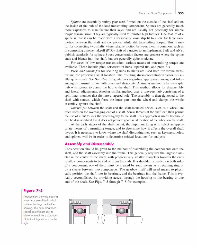
Assembly and DisassemblyConsideration should be given to the method of assembling the components onto theshaft, and the shaft assembly into the frame. This generally requires the largest diam-eter in the center of the shaft, with progressively smaller diameters towards the endsto allow components to be slid on from the ends. If a shoulder is needed on both sidesof a component, one of them must be created by such means as a retaining ring orby a sleeve between two components. The gearbox itself will need means to physi-cally position the shaft into its bearings, and the bearings into the frame. This is typ-ically accomplished by providing access through the housing to the bearing at oneend of the shaft. See Figs. 7–5 through 7–8 for examples.
Figure 7–5
Arrangement showing bearinginner rings press-fitted to shaftwhile outer rings float in thehousing. The axial clearanceshould be sufficient only toallow for machinery vibrations.Note the labyrinth seal on theright.
bud21932_ch07_346-394 09/11/2006 05:57 PM Page 353CONFIRMING PAGES

354 Mechanical Engineering Design
Figure 7–6
Similar to the arrangement ofFig. 7--5 except that the outerbearing rings are preloaded.
Figure 7–7
In this arrangement the inner ring of the left-hand bearing is locked to the shaft between anut and a shaft shoulder. The locknut and washer are AFBMA standard. The snap ring inthe outer race is used to positively locate the shaft assembly in the axial direction. Notethe floating right-hand bearing and the grinding runout grooves in the shaft.
When components are to be press-fit to the shaft, the shaft should be designedso that it is not necessary to press the component down a long length of shaft. Thismay require an extra change in diameter, but it will reduce manufacturing and assem-bly cost by only requiring the close tolerance for a short length.
Consideration should also be given to the necessity of disassembling the compo-nents from the shaft. This requires consideration of issues such as; accessibility ofretaining rings, space for pullers to access bearings, openings in the housing to allowpressing the shaft or bearings out, etc.
7–4 Shaft Design for Stress
Critical LocationsIt is not necessary to evaluate the stresses in a shaft at every point; a few potentiallycritical locations will suffice. Critical locations will usually be on the outer surface,at axial locations where the bending moment is large, where the torque is present, andwhere stress concentrations exist. By direct comparison of various points along theshaft, a few critical locations can be identified upon which to base the design. Anassessment of typical stress situations will help.
Figure 7–8
This arrangement is similar toFig. 7--7 in that the left-handbearing positions the entireshaft assembly. In this casethe inner ring is secured tothe shaft using a snap ring.Note the use of a shield toprevent dirt generated from within the machine fromentering the bearing.
bud21932_ch07_346-394 09/11/2006 05:57 PM Page 354CONFIRMING PAGES

Shafts and Shaft Components 355
Most shafts will transmit torque through a portion of the shaft. Typically thetorque comes into the shaft at one gear and leaves the shaft at another gear. A freebody diagram of the shaft will allow the torque at any section to be determined. Thetorque is often relatively constant at steady state operation. The shear stress due tothe torsion will be greatest on outer surfaces.
The bending moments on a shaft can be determined by shear and bendingmoment diagrams. Since most shaft problems incorporate gears or pulleys that intro-duce forces in two planes, the shear and bending moment diagrams will generallybe needed in two planes. Resultant moments are obtained by summing moments asvectors at points of interest along the shaft. The phase angle of the moments is notimportant since the shaft rotates. A steady bending moment will produce a com-pletely reversed moment on a rotating shaft, as a specific stress element will alter-nate from compression to tension in every revolution of the shaft. The normal stressdue to bending moments will be greatest on the outer surfaces. In situations wherea bearing is located at the end of the shaft, stresses near the bearing are often notcritical since the bending moment is small.
Axial stresses on shafts due to the axial components transmitted through heli-cal gears or tapered roller bearings will almost always be negligibly small comparedto the bending moment stress. They are often also constant, so they contribute lit-tle to fatigue. Consequently, it is usually acceptable to neglect the axial stressesinduced by the gears and bearings when bending is present in a shaft. If an axialload is applied to the shaft in some other way, it is not safe to assume it is negli-gible without checking magnitudes.
Shaft StressesBending, torsion, and axial stresses may be present in both midrange and alternatingcomponents. For analysis, it is simple enough to combine the different types ofstresses into alternating and midrange von Mises stresses, as shown in Sec. 6–14, p. 309. It is sometimes convenient to customize the equations specifically for shaftapplications. Axial loads are usually comparatively very small at critical locationswhere bending and torsion dominate, so they will be left out of the following equa-tions. The fluctuating stresses due to bending and torsion are given by
σa = K fMac
Iσm = K f
Mmc
I(7–1)
τa = K f sTac
Jτm = K f s
Tmc
J(7–2)
where Mm and Ma are the midrange and alternating bending moments, Tm and Ta arethe midrange and alternating torques, and K f and K f s are the fatigue stress concen-tration factors for bending and torsion, respectively.
Assuming a solid shaft with round cross section, appropriate geometry terms canbe introduced for c, I, and J resulting in
σa = K f32Ma
πd3σm = K f
32Mm
πd3(7–3)
τa = K f s16Ta
πd3τm = K f s
16Tm
πd3(7–4)
bud21932_ch07_346-394 09/11/2006 05:57 PM Page 355CONFIRMING PAGES

356 Mechanical Engineering Design
Combining these stresses in accordance with the distortion energy failure theory,the von Mises stresses for rotating round, solid shafts, neglecting axial loads, are givenby
σ ′a = (σ 2
a + 3τ 2a )1/2 =
[(32K f Ma
πd3
)2
+ 3
(16K f s Ta
πd3
)2]1/2
(7–5)
σ ′m = (σ 2
m + 3τ 2m)1/2 =
[(32K f Mm
πd3
)2
+ 3
(16K f s Tm
πd3
)2]1/2
(7–6)
Note that the stress concentration factors are sometimes considered optional for themidrange components with ductile materials, because of the capacity of the ductilematerial to yield locally at the discontinuity.
These equivalent alternating and midrange stresses can be evaluated using anappropriate failure curve on the modified Goodman diagram (See Sec. 6–12, p. 295,and Fig. 6–27). For example, the fatigue failure criteria for the modified Goodmanline as expressed previously in Eq. (6–46) is
1
n= σ ′
a
Se+ σ ′
m
Sut
Substitution of σ ′a and σ ′
m from Eqs. (7–5) and (7–6) results in
1
n= 16
πd3
{1
Se
[4(K f Ma)
2 + 3(K f s Ta)2]1/2 + 1
Sut
[4(K f Mm)2 + 3(K f s Tm)2]1/2
}For design purposes, it is also desirable to solve the equation for the diameter.
This results in
d =(
16n
π
{1
Se
[4(K f Ma)
2 + 3(K f s Ta)2]1/2
+ 1
Sut
[4(K f Mm)2 + 3(K f s Tm)2]1/2
})1/3
Similar expressions can be obtained for any of the common failure criteria by sub-stituting the von Mises stresses from Eqs. (7–5) and (7–6) into any of the failurecriteria expressed by Eqs. (6–45) through (6–48), p. 298. The resulting equationsfor several of the commonly used failure curves are summarized below. The namesgiven to each set of equations identifies the significant failure theory, followed bya fatigue failure locus name. For example, DE-Gerber indicates the stresses arecombined using the distortion energy (DE) theory, and the Gerber locus is used forthe fatigue failure.
DE-Goodman
1
n= 16
πd3
{1
Se
[4(K f Ma)
2 + 3(K f s Ta)2]1/2 + 1
Sut
[4(K f Mm)2 + 3(K f s Tm)2]1/2
}(7–7)
d =(
16n
π
{1
Se
[4(K f Ma)
2 + 3(K f s Ta)2]1/2
+ 1
Sut
[4(K f Mm)2 + 3(K f s Tm)2]1/2
})1/3
(7–8)
bud21932_ch07_346-394 09/11/2006 05:57 PM Page 356CONFIRMING PAGES

Shafts and Shaft Components 357
DE-Gerber
1
n= 8A
πd3Se
⎧⎨⎩1 +[
1 +(
2BSe
ASut
)2]1/2
⎫⎬⎭ (7–9)
d =⎛⎝8n A
π Se
⎧⎨⎩1 +[
1 +(
2BSe
ASut
)2]1/2
⎫⎬⎭⎞⎠1/3
(7–10)
where
A =√
4(K f Ma)2 + 3(K f s Ta)2
B =√
4(K f Mm)2 + 3(K f s Tm)2
DE-ASME Elliptic
1
n= 16
πd3
[4
(K f Ma
Se
)2
+ 3
(K f s Ta
Se
)2
+ 4
(K f Mm
Sy
)2
+ 3
(K f s Tm
Sy
)2]1/2
(7–11)
d =⎧⎨⎩16n
π
[4
(K f Ma
Se
)2
+ 3
(K f s Ta
Se
)2
+ 4
(K f Mm
Sy
)2
+ 3
(K f s Tm
Sy
)2]1/2
⎫⎬⎭1/3
(7–12)
DE-Soderberg
d =(
16n
π
{1
Se
[4(K f Ma)
2 + 3(K f s Ta)2]1/2
+ 1
Syt
[4(K f Mm)2 + 3(K f s Tm)2]1/2
})1/3
(7–13)
1
n= 16
πd3
{1
Se
[4(K f Ma)
2 + 3(K f s Ta)2]1/2 + 1
Syt
[4(K f Mm)2 + 3(K f s Tm)2]1/2
}(7–14)
For a rotating shaft with constant bending and torsion, the bending stress is com-pletely reversed and the torsion is steady. Equations (7–7) through (7–14) can be sim-plified by setting Mm and Ta equal to 0, which simply drops out some of the terms.
Note that in an analysis situation in which the diameter is known and the factorof safety is desired, as an alternative to using the specialized equations above, it isalways still valid to calculate the alternating and mid-range stresses using Eqs. (7–5)and (7–6), and substitute them into one of the equations for the failure criteria, Eqs.(6–45) through (6–48), and solve directly for n. In a design situation, however, hav-ing the equations pre-solved for diameter is quite helpful.
It is always necessary to consider the possibility of static failure in the first load cycle.The Soderberg criteria inherently guards against yielding, as can be seen by noting thatits failure curve is conservatively within the yield (Langer) line on Fig. 6–27, p. 297. TheASME Elliptic also takes yielding into account, but is not entirely conservative
bud21932_ch07_346-394 09/11/2006 05:57 PM Page 357CONFIRMING PAGES

358 Mechanical Engineering Design
throughout its entire range. This is evident by noting that it crosses the yield line in Fig. 6–27. The Gerber and modified Goodman criteria do not guard against yielding,requiring a separate check for yielding. A von Mises maximum stress is calculated forthis purpose.
σ ′max = [
(σm + σa)2 + 3 (τm + τa)2]1/2
=[(
32K f (Mm + Ma)
πd3
)2
+ 3
(16K f s (Tm + Ta)
πd3
)2]1/2
(7–15)
To check for yielding, this von Mises maximum stress is compared to the yieldstrength, as usual.
ny = Sy
σ ′max
(7–16)
For a quick, conservative check, an estimate for σ ′max can be obtained by simply
adding σ ′a and σ ′
m . (σ ′a + σ ′
m ) will always be greater than or equal to σ ′max, and will
therefore be conservative.
EXAMPLE 7–1 At a machined shaft shoulder the small diameter d is 1.100 in, the large diameter Dis 1.65 in, and the fillet radius is 0.11 in. The bending moment is 1260 lbf · in andthe steady torsion moment is 1100 lbf · in. The heat-treated steel shaft has an ultimatestrength of Sut = 105 kpsi and a yield strength of Sy = 82 kpsi. The reliability goalis 0.99.
(a) Determine the fatigue factor of safety of the design using each of the fatigue failurecriteria described in this section.
(b) Determine the yielding factor of safety.
Solution (a) D/d = 1.65/1.100 = 1.50, r/d = 0.11/1.100 = 0.10, Kt = 1.68 (Fig. A–15–9),Kts = 1.42 (Fig. A–15–8), q = 0.85 (Fig. 6–20), qshear = 0.92 (Fig. 6–21).
From Eq. (6–32),
K f = 1 + 0.85(1.68 − 1) = 1.58
K f s = 1 + 0.92(1.42 − 1) = 1.39
Eq. (6–8): S′e = 0.5(105) = 52.5 kpsi
Eq. (6–19): ka = 2.70(105)−0.265 = 0.787
Eq. (6–20): kb =(
1.100
0.30
)−0.107
= 0.870
kc = kd = kf = 1
bud21932_ch07_346-394 09/11/2006 05:57 PM Page 358CONFIRMING PAGES

Shafts and Shaft Components 359
Table 6–6 ke = 0.814
Se = 0.787(0.870)0.814(52.5) = 29.3 kpsi
For a rotating shaft, the constant bending moment will create a completely reversedbending stress.
Ma = 1260 lbf · in Tm = 1100 lbf · in Mm = Ta = 0
Applying Eq. (7–7) for the DE-Goodman criteria gives
1
n= 16
π(1.1)3
{[4 (1.58 · 1260)2
]1/2
29 300+
[3 (1.39 · 1100)2
]1/2
105 000
}= 0.615
Answer n = 1.62 DE-Goodman
Similarly, applying Eqs. (7–9), (7–11), and (7–13) for the other failure criteria,
Answer n = 1.87 DE-Gerber
Answer n = 1.88 DE-ASME Elliptic
Answer n = 1.56 DE-Soderberg
For comparison, consider an equivalent approach of calculating the stresses and apply-ing the fatigue failure criteria directly. From Eqs. (7–5) and (7–6),
σ ′a =
[(32 · 1.58 · 1260
π (1.1)3
)2]1/2
= 15 235 psi
σ ′m =
[3
(16 · 1.39 · 1100
π (1.1)3
)2]1/2
= 10 134 psi
Taking, for example, the Goodman failure critera, application of Eq. (6–46) gives
1
n= σ ′
a
Se+ σ ′
m
Sut= 15 235
29 300+ 10 134
105 000= 0.616
n = 1.62
which is identical with the previous result. The same process could be used for theother failure criteria.
(b) For the yielding factor of safety, determine an equivalent von Mises maximumstress using Eq. (7–15).
σ ′max =
[(32(1.58) (1260)
π (1.1)3
)2
+ 3
(16(1.39) (1100)
π (1.1)3
)2]1/2
= 18 300 psi
Answer ny = Sy
σ ′max
= 82 000
18 300= 4.48
For comparison, a quick and very conservative check on yielding can be obtainedby replacing σ ′
max with σ ′a + σ ′
m . This just saves the extra time of calculating σ ′max
if σ ′a and σ ′
m have already been determined. For this example,
bud21932_ch07_346-394 09/11/2006 05:57 PM Page 359CONFIRMING PAGES
360 Mechanical Engineering Design
ny = Sy
σ ′a + σ ′
m
= 82 000
15 235 + 10 134= 3.23
which is quite conservative compared with ny � 4.48.
Estimating Stress ConcentrationsThe stress analysis process for fatigue is highly dependent on stress concentrations.Stress concentrations for shoulders and keyways are dependent on size specificationsthat are not known the first time through the process. Fortunately, since these elementsare usually of standard proportions, it is possible to estimate the stress concentrationfactors for initial design of the shaft. These stress concentrations will be fine-tuned insuccessive iterations, once the details are known.
Shoulders for bearing and gear support should match the catalog recommenda-tion for the specific bearing or gear. A look through bearing catalogs shows that atypical bearing calls for the ratio of D/d to be between 1.2 and 1.5. For a first approx-imation, the worst case of 1.5 can be assumed. Similarly, the fillet radius at the shoul-der needs to be sized to avoid interference with the fillet radius of the mating com-ponent. There is a significant variation in typical bearings in the ratio of fillet radiusversus bore diameter, with r/d typically ranging from around 0.02 to 0.06. A quicklook at the stress concentration charts (Figures A–15–8 and A–15–9) shows that thestress concentrations for bending and torsion increase significantly in this range. Forexample, with D/d = 1.5 for bending, Kt = 2.7 at r/d = 0.02, and reduces toKt = 2.1 at r/d = 0.05, and further down to Kt = 1.7 at r/d = 0.1. This indicatesthat this is an area where some attention to detail could make a significant difference.Fortunately, in most cases the shear and bending moment diagrams show that bend-ing moments are quite low near the bearings, since the bending moments from theground reaction forces are small.
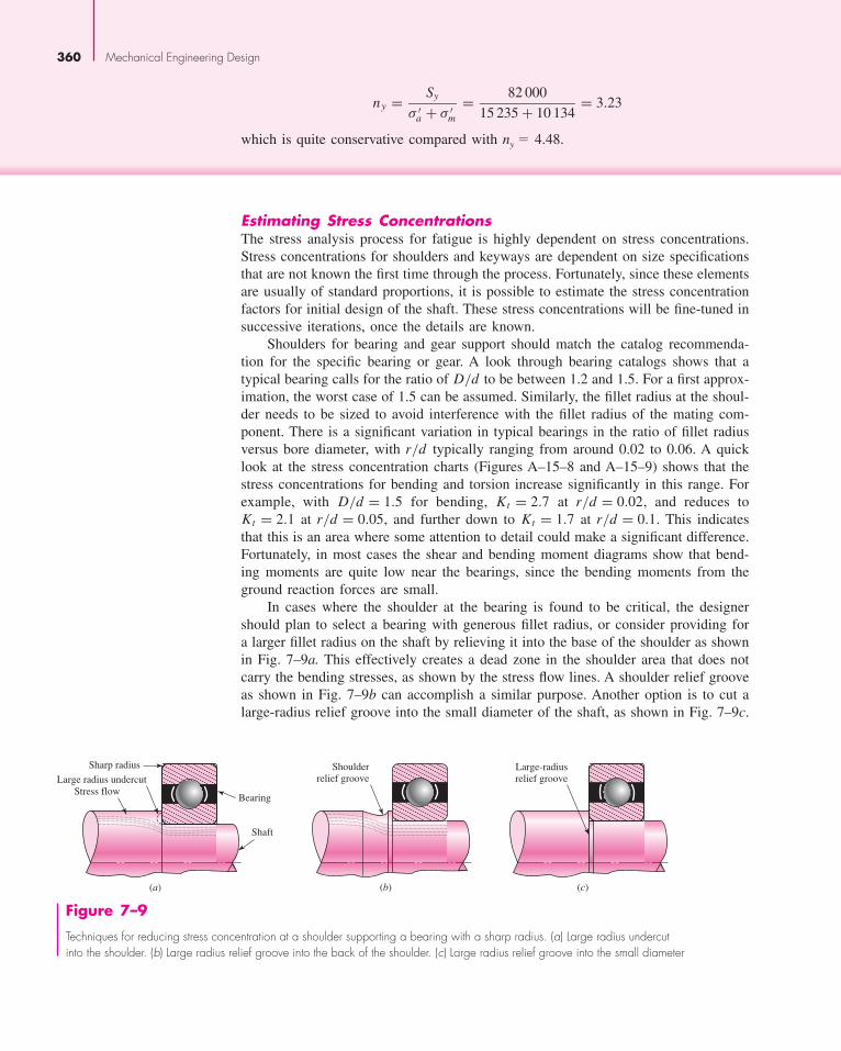
In cases where the shoulder at the bearing is found to be critical, the designershould plan to select a bearing with generous fillet radius, or consider providing fora larger fillet radius on the shaft by relieving it into the base of the shoulder as shownin Fig. 7–9a. This effectively creates a dead zone in the shoulder area that does notcarry the bending stresses, as shown by the stress flow lines. A shoulder relief grooveas shown in Fig. 7–9b can accomplish a similar purpose. Another option is to cut alarge-radius relief groove into the small diameter of the shaft, as shown in Fig. 7–9c.
Sharp radius
Bearing
Shaft
Large radius undercutStress flow
(a)
Shoulderrelief groove
(b)
Large-radiusrelief groove
(c)
Figure 7–9
Techniques for reducing stress concentration at a shoulder supporting a bearing with a sharp radius. (a) Large radius undercut into the shoulder. (b) Large radius relief groove into the back of the shoulder. (c) Large radius relief groove into the small diameter
bud21932_ch07_346-394 09/11/2006 05:57 PM Page 360CONFIRMING PAGES
Shafts and Shaft Components 361
This has the disadvantage of reducing the cross-sectional area, but is often used incases where it is useful to provide a relief groove before the shoulder to prevent thegrinding or turning operation from having to go all the way to the shoulder.
For the standard shoulder fillet, for estimating Kt values for the first iteration, anr/d ratio should be selected so Kt values can be obtained. For the worst end of thespectrum, with r/d = 0.02 and D/d = 1.5, Kt values from the stress concentrationcharts for shoulders indicate 2.7 for bending, 2.2 for torsion, and 3.0 for axial.
A keyway will produce a stress concentration near a critical point where the load-transmitting component is located. The stress concentration in an end-milled keyseatis a function of the ratio of the radius r at the bottom of the groove and the shaftdiameter d. For early stages of the design process, it is possible to estimate the stressconcentration for keyways regardless of the actual shaft dimensions by assuming atypical ratio of r/d = 0.02. This gives Kt = 2.2 for bending and Kts = 3.0 for tor-sion, assuming the key is in place.
Figures A–15–16 and A–15–17 give values for stress concentrations for flat-bottomed grooves such as used for retaining rings. By examining typical retaining ringspecifications in vendor catalogs, it can be seen that the groove width is typically slightlygreater than the groove depth, and the radius at the bottom of the groove is around 1/10of the groove width. From Figs. A–15–16 and A–15–17, stress concentration factors fortypical retaining ring dimensions are around 5 for bending and axial, and 3 for torsion.Fortunately, the small radius will often lead to a smaller notch sensitivity, reducing K f .
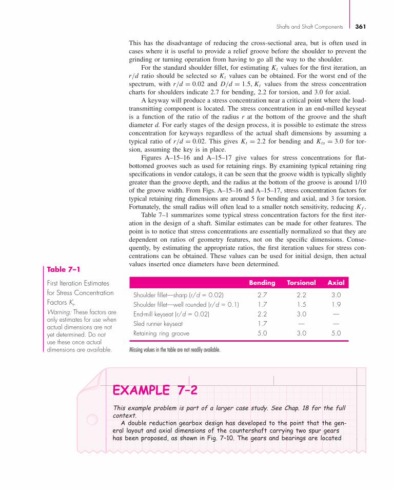
Table 7–1 summarizes some typical stress concentration factors for the first iter-ation in the design of a shaft. Similar estimates can be made for other features. Thepoint is to notice that stress concentrations are essentially normalized so that they aredependent on ratios of geometry features, not on the specific dimensions. Conse-quently, by estimating the appropriate ratios, the first iteration values for stress con-centrations can be obtained. These values can be used for initial design, then actualvalues inserted once diameters have been determined.
Table 7–1
First Iteration Estimatesfor Stress ConcentrationFactors Kt.Warning: These factors areonly estimates for use whenactual dimensions are notyet determined. Do notuse these once actualdimensions are available.
Bending Torsional Axial
Shoulder fillet—sharp (r/d � 0.02) 2.7 2.2 3.0Shoulder fillet—well rounded (r/d � 0.1) 1.7 1.5 1.9End-mill keyseat (r/d � 0.02) 2.2 3.0 —Sled runner keyseat 1.7 — —Retaining ring groove 5.0 3.0 5.0
Missing values in the table are not readily available.
EXAMPLE 7–2This example problem is part of a larger case study. See Chap. 18 for the fullcontext.
A double reduction gearbox design has developed to the point that the gen-eral layout and axial dimensions of the countershaft carrying two spur gearshas been proposed, as shown in Fig. 7–10. The gears and bearings are located
bud21932_ch07_346-394 09/11/2006 05:57 PM Page 361CONFIRMING PAGES

362 Mechanical Engineering Design
0.25
"D
atum
3.50
"
9.50
"9.
75"
10.2
5"
10.7
5"
11.2
5"
11.5
0"
8.50
"
7.50
"
2.75
"
2.0"
1.75
"
1.25
"
0.75
"
C A D E F
D1 D2
D3
D4
D5
D6 D7
Gear 3D3 � 12
Bearing A Bearing B
Gear 4D5 � 2.67
G H I J K L M B N
Figure 7–10
Shaft layout for Example 7–2.
and supported by shoulders, and held in place by retaining rings. The gearstransmit torque through keys. Gears have been specified as shown, allowing thetangential and radial forces transmitted through the gears to the shaft to bedetermined as follows.
W t23 = 540 lbf W t
54 = −2431 lbf
W r23 = −197 lbf W r
54 = −885 lbf
where the superscripts t and r represent tangential and radial directions,respectively; and, the subscripts 23 and 54 represent the forces exerted bygears 2 and 5 (not shown) on gears 3 and 4, respectively.
Proceed with the next phase of the design, in which a suitable material isselected, and appropriate diameters for each section of the shaft areestimated, based on providing sufficient fatigue and static stress capacity forinfinite life of the shaft, with minimum safety factors of 1.5.
SolutionPerform free body diagram analysis to get reaction forces at the bearings.
RAz = 115.0 lbf
RAy = 356.7 lbf
RBz = 1776.0 lbf
RBy = 725.3 lbf
From �Mx , find the torque in the shaft between the gears, T = W t23(d3/2) =
540 (12/2) = 3240 lbf · inGenerate shear-moment diagrams for two planes.Combine orthogonal planes as vectors to get total moments, e.g.√
39962 + 16322 = 4316 lbf.Start with Point I, where the bending moment is high, there is a stress con-
centration at the shoulder, and the torque is present.
At I , Ma = 3651 lbf-in, Tm = 3240 lbf-in, Mm = Ta = 0
Assume generous fillet radius for gear at I.
bud21932_ch07_346-394 09/11/2006 05:57 PM Page 362CONFIRMING PAGES

Shafts and Shaft Components 363
From Table 7–1, estimate Kt = 1.7, Kts = 1.5. For quick, conservative firstpass, assume K f = Kt , K f s = Kts .
Choose inexpensive steel, 1020 CD, with Sut = 68 kpsi. For Se,
Eq. (6–19) ka = aSbut = 2.7(68)−0.265 = 0.883
BA
RBy
RBzRAz
RAy
x
y
z
W54t
W23t
W23r
W54r
655
39963341
2302220
�1776x-z Plane
115V
M
160
1632
1472
713907
�725
x-y Plane
357V
M
43163651
7492398
MTOT
3240
T
A G J B
A G
I K
J B
bud21932_ch07_346-394 09/11/2006 05:57 PM Page 363CONFIRMING PAGES

364 Mechanical Engineering Design
Guess kb = 0.9. Check later when d is known.
kc = kd = ke = 1
Eq. (6–18) Se = (0.883)(0.9)(0.5)(68) = 27.0kpsi.
For first estimate of the small diameter at the shoulder at point I, use the DE-Goodman criterion of Eq. (7–8). This criterion is good for the initial design,since it is simple and conservative. With Mm = Ta = 0, Eq. (7–8) reduces to
d =
⎧⎪⎨⎪⎩16n
π
⎛⎜⎝2(K f Ma
)Se
+[3(K f s Tm
)2]1/2
Sut
⎞⎟⎠⎫⎪⎬⎪⎭
1/3
d ={
16(1.5)
π
(2 (1.7) (3651)
27 000+
{3 [(1.5) (3240)]2
}1/2
68 000
)}1/3
d = 1.65 in.
All estimates have probably been conservative, so select the next standard sizebelow 1.65 in. and check, d � 1.625 in.
A typical D/d ratio for support at a shoulder is D/d � 1.2 in.,D � 1.2(1.625) � 1.95 in. Increase to D � 2.0 in. A nominal 2 in. cold-drawn shaftdiameter can be used. Check if estimates were acceptable.
D/d = 2/1.625 = 1.23
Assume fillet radius r = d/10 ∼= 0.16 in. r/d = 0.1
Kt = 1.6 (Fig. A–15–9), q = 0.82 (Fig. 6–20)
Eq. (6–32) K f = 1 + 0.82(1.6 − 1) = 1.49
Kts = 1.35 (Fig. A–15–8), qs = 0.95 (Fig. 6–21)
K f s = 1 + 0.95(1.35 − 1) = 1.33
ka = 0.883 (no change)
Eq. (6–20) kb =(
1.625
0.3
)−0.107
= 0.835
Se = (0.883)(0.835)(0.5)(68) = 25.1 kpsi
Eq. (7–5) σ ′a = 32K f Ma
πd3= 32(1.49)(3651)
π(1.625)3= 12 910 psi
Eq. (7–6) σ ′m =
[3
(16K f s Tm
πd3
)2]1/2
=√
3(16)(1.33)(3240)
π(1.625)3= 8859 psi
Using Goodman criterion
1
n f= σ ′
a
Se+ σ ′
m
Sut= 129 10
25 100+ 8859
68 000= 0.645
n f = 1.55
Note that we could have used Eq. (7–7) directly.
bud21932_ch07_346-394 09/11/2006 05:57 PM Page 364CONFIRMING PAGES

Shafts and Shaft Components 365
Check yielding.
ny = Sy
σ ′max
>Sy
σ ′a + σ ′
m
= 57 000
12 910 + 8859= 2.62
Also check this diameter at the end of the keyway, just to the right of point I,and at the groove at point K. From moment diagram, estimate M at end of keyway to be M � 3750 lbf-in.
Assume the radius at the bottom of the keyway will be the standard r�d � 0.02, r � 0.02 d � 0.02 (1.625) � 0.0325 in.
Kt = 2.14 (Fig. A–15–18), q � 0.65 (Fig. 6–20)
K f = 1 + 0.65(2.14 − 1) = 1.74
Kts = 3.0 (Fig. A–15–19), qs = 0.9 (Fig. 6–21)
K f s = 1 + 0.9(3 − 1) = 2.8
σ ′a = 32K f Ma
πd3= 32(1.74)(3750)
π(1.625)3= 15 490 psi
σ ′m =
√3(16)
K f s Tm
πd3=
√3(16)(2.8)(3240)
π(1.625)3= 18 650 psi
1
n f= σ ′
a
Se+ σ ′
m
Sut= 15 490
25 100+ 18 650
68 000= 0.891
n f = 1.12
The keyway turns out to be more critical than the shoulder. We can eitherincrease the diameter, or use a higher strength material. Unless the deflectionanalysis shows a need for larger diameters, let us choose to increase thestrength. We started with a very low strength, and can afford to increase itsome to avoid larger sizes. Try 1050 CD, with Sut = 100 kpsi.
Recalculate factors affected by Sut , i.e. ka → Se; q → K f → σ ′a
ka = 2.7(100)−0.265 = 0.797, Se = 0.797(0.835)(0.5)(100) = 33.3 kpsi
q = 0.72, K f = 1 + 0.72(2.14 − 1) = 1.82
σ ′a = 32(1.82)(3750)
π(1.625)3= 16 200 psi
1
n f= 16 200
33 300+ 18 650
100 000= 0.673
n f = 1.49
Since the Goodman criterion is conservative, we will accept this as close enoughto the requested 1.5.
Check at the groove at K, since Kt for flat-bottomed grooves are often veryhigh. From the torque diagram, note that no torque is present at the groove.From the moment diagram, Ma = 2398 lbf � in, Mm = Ta = Tm = 0. To quicklycheck if this location is potentially critical just use K f = Kt = 5.0 as anestimate, from Table 7–1.
σa = 32K f Ma
πd3= 32(5)(2398)
π(1.625)3= 28 460 psi
n f = Se
σa= 33 300
28 460= 1.17
bud21932_ch07_346-394 09/11/2006 05:57 PM Page 365CONFIRMING PAGES
366 Mechanical Engineering Design
This is low. We will look up data for a specific retaining ring to obtain K f moreaccurately. With a quick on-line search of a retaining ring specification usingthe website www.globalspec.com, appropriate groove specifications for a retain-ing ring for a shaft diameter of 1.625 in. The following are obtained: width,a = 0.068 in; depth, t = 0.048 in; and corner radius at bottom of groove,r = 0.01in.
From Fig. A–15–16, with r/t = 0.01
0.048= 0.208 , and a/t = 0.068
0.048= 1.42
Kt = 4.3 , q = 0.65 (Fig. 6–20)
K f = 1 + 0.65(4.3 − 1) = 3.15
σa = 32K f Ma
πd3= 32(3.15)(2398)
π(1.625)3= 17 930 psi
n f = Se
σa= 33 300
17 930= 1.86
Quickly check if point M might be critical. Only bending is present, and themoment is small, but the diameter is small and the stress concentration is highfor a sharp fillet required for a bearing. From the moment diagram, Ma = 959 lbf · in, and Mm = Tm = Ta = 0
Estimate Kt = 2.7 from Table 7–1, d = 1.0 in, and fillet radius r to fit typicalbearing.
r/d = 0.02, r = 0.02(1) = 0.02
q = 0.7 (Fig. 6–20)
K f = 1 + (0.7)(2.7 − 1) = 2.19
σa = 32K f Ma
πd3= 32(2.19)(959)
π(1)3= 21 390 psi
n f = Se
σa= 33 300
21 390= 1.56
Should be OK. Close enough to recheck after bearing is selected.With the diameters specified for the critical locations, fill in trial values for
the rest of the diameters, taking into account typical shoulder heights forbearing and gear support.
D1 = D7 = 1.0 in
D2 = D6 = 1.4 in
D3 = D5 = 1.625 in
D4 = 2.0 in
The bending moments are much less on the left end of shaft, so D1, D2, and D3could be smaller. However, unless weight is an issue, there is little advantage torequiring more material removal. Also, the extra rigidity may be needed to keepdeflections small.
bud21932_ch07_346-394 09/11/2006 05:58 PM Page 366CONFIRMING PAGES

Shafts and Shaft Components 367
7–5 Deflection ConsiderationsDeflection analysis at even a single point of interest requires complete geometry infor-mation for the entire shaft. For this reason, it is desirable to design the dimensions atcritical locations to handle the stresses, and fill in reasonable estimates for all otherdimensions, before performing a deflection analysis. Deflection of the shaft, both lin-ear and angular, should be checked at gears and bearings. Allowable deflections willdepend on many factors, and bearing and gear catalogs should be used for guidanceon allowable misalignment for specific bearings and gears. As a rough guideline, typ-ical ranges for maximum slopes and transverse deflections of the shaft centerline aregiven in Table 7–2. The allowable transverse deflections for spur gears are dependenton the size of the teeth, as represented by the diametral pitch P � number ofteeth/pitch diameter.
In Sec. 4–4 several beam deflection methods are described. For shafts, where thedeflections may be sought at a number of different points, integration using eithersingularity functions or numerical integration is practical. In a stepped shaft, the cross-sectional properties change along the shaft at each step, increasing the complexity ofintegration, since both M and I vary. Fortunately, only the gross geometric dimensionsneed to be included, as the local factors such as fillets, grooves, and keyways do nothave much impact on deflection. Example 4–7 demonstrates the use of singularityfunctions for a stepped shaft. Many shafts will include forces in multiple planes,requiring either a three dimensional analysis, or the use of superposition to obtaindeflections in two planes which can then be summed as vectors.
A deflection analysis is straightforward, but it is lengthy and tedious to carry outmanually, particularly for multiple points of interest. Consequently, practically allshaft deflection analysis will be evaluated with the assistance of software. Anygeneral-purpose finite-element software can readily handle a shaft problem (see Chap. 19). This is practical if the designer is already familiar with using the softwareand with how to properly model the shaft. Special-purpose software solutions for 3-D shaft analysis are available, but somewhat expensive if only used occasionally.Software requiring very little training is readily available for planar beam analysis,and can be downloaded from the internet. Example 7–3 demonstrates how to incor-porate such a program for a shaft with forces in multiple planes.
Slopes
Tapered roller 0.0005–0.0012 radCylindrical roller 0.0008–0.0012 radDeep-groove ball 0.001–0.003 radSpherical ball 0.026–0.052 radSelf-align ball 0.026–0.052 radUncrowned spur gear � 0.0005 rad
Transverse deflections
Spur gears with P < 10 teeth/in 0.010 inSpur gears with 11 < P < 19 0.005 inSpur gears with 20 < P < 50 0.003 in
Table 7–2
Typical MaximumRanges for Slopes andTransverse Deflections
bud21932_ch07_346-394 09/11/2006 05:58 PM Page 367CONFIRMING PAGES

368 Mechanical Engineering Design
Beam length: 11.5 in
Deflection
in
xy plane
Slope
deg
Moment
lbf-in
Shear
lbf
Beam length: 11.5 in
Deflection
in
xz plane
Slope
deg
Moment
lbf-in
Shear
lbf
Figure 7–11
Shear, moment, slope, and deflection plots from two planes. (Source: Beam 2D Stress Analysis, OrandSystems, Inc.)
EXAMPLE 7–3This example problem is part of a larger case study. See Chap. 18 for the full context.In Example 7–2 a preliminary shaft geometry was obtained on the basis of
design for stress. The resulting shaft is shown in Fig. 7–10, with proposeddiameters of
D1 = D7 = 1 in
D2 = D6 = 1.4 in
D3 = D5 = 1.625 in
D4 = 2.0 in
Check that the deflections and slopes at the gears and bearings are acceptable.If necessary, propose changes in the geometry to resolve any problems.
SolutionA simple planar beam analysis program will be used. By modeling the shafttwice, with loads in two orthogonal planes, and combining the results, the shaftdeflections can readily be obtained. For both planes, the material is selected(steel with E = 30 Mpsi), the shaft lengths and diameters are entered, and thebearing locations are specified. Local details like grooves and keyways areignored, as they will have insignificant effect on the deflections. Then the tan-gential gear forces are entered in the horizontal xy plane model, and the radialgear forces are entered in the vertical yz plane model. The software can calcu-late the bearing reaction forces, and numerically integrate to generate plotsfor shear, moment, slope, and deflection, as shown in Fig. 7–11.
bud21932_ch07_346-394 09/11/2006 05:58 PM Page 368CONFIRMING PAGES

Shafts and Shaft Components 369
The deflections and slopes at points of interest are obtained from the plots,and combined with orthogonal vector addition, that is, δ =
√δ2
xz + δ2xy . Results
are shown in Table 7–3.Whether these values are acceptable will depend on the specific bearings
and gears selected, as well as the level of performance expected. According to the guidelines in Table 7–2, all of the bearing slopes are well below typicallimits for ball bearings. The right bearing slope is within the typical range forcylindrical bearings. Since the load on the right bearing is relatively high, acylindrical bearing might be used. This constraint should be checked against the specific bearing specifications once the bearing is selected.
The gear slopes and deflections more than satisfy the limits recommendedin Table 7–2. It is recommended to proceed with the design, with an awareness that changes that reduce rigidity should warrant anotherdeflection check.
Point of interest xz plane xy plane Total
Left bearing slope 0.02263 deg 0.01770 deg 0.02872 deg0.000501 rad
Right bearing slope 0.05711 deg 0.02599 deg 0.06274 deg0.001095 rad
Left gear slope 0.02067 deg 0.01162 deg 0.02371 deg0.000414 rad
Right gear slope 0.02155 deg 0.01149 deg 0.02442 deg0.000426 rad
Left gear deflection 0.0007568 in 0.0005153 in 0.0009155 inRight gear deflection 0.0015870 in 0.0007535 in 0.0017567 in
Table 7–3
Slope and Deflection Values at Key Locations
Once deflections at various points have been determined, if any value is largerthan the allowable deflection at that point, a new diameter can be found from
dnew = dold
∣∣∣∣nd yold
yall
∣∣∣∣1/4
(7–17)
where yall is the allowable deflection at that station and nd is the design factor. Similarly,if any slope is larger than the allowable slope θall, a new diameter can be found from
dnew = dold
∣∣∣∣nd (dy/dx)old
(slope)all
∣∣∣∣1/4
(7–18)
where (slope)all is the allowable slope. As a result of these calculations, determine thelargest dnew/dold ratio, then multiply all diameters by this ratio. The tight constraintwill be just tight, and all others will be loose. Don’t be too concerned about end jour-nal sizes, as their influence is usually negligible. The beauty of the method is that thedeflections need to be completed just once and constraints can be rendered loose butfor one, with diameters all identified without reworking every deflection.
bud21932_ch07_346-394 09/11/2006 05:58 PM Page 369CONFIRMING PAGES

370 Mechanical Engineering Design
2C.R. Mischke, “Tabular Method for Transverse Shear Deflection,” Sec. 17.3 in Joseph E. Shigley, CharlesR. Mischke, and Thomas H. Brown, Jr. (eds.), Standard Handbook of Machine Design, 3rd ed., McGraw-Hill, New York, 2004.3R. Bruce Hopkins, Design Analysis of Shafts and Beams, McGraw-Hill, New York, 1970, pp. 93–99.
The transverse shear V at a section of a beam in flexure imposes a shearing deflec-tion, which is superposed on the bending deflection. Usually such shearing deflectionis less than 1 percent of the transverse bending deflection, and it is seldom evaluated.However, when the shaft length-to-diameter ratio is less than 10, the shear compo-nent of transverse deflection merits attention. There are many short shafts. A tabularmethod is explained in detail, with examples elsewhere2.
For right-circular cylindrical shafts in torsion the angular deflection θ is given inEq. (4–5). For a stepped shaft with individual cylinder length li and torque Ti , theangular deflection can be estimated from
θ =∑
θi =∑ Tili
Gi Ji(7–19)
or, for a constant torque throughout homogeneous material, from
θ = T
G
∑ li
Ji(7–20)
This should be treated only as an estimate, since experimental evidence shows thatthe actual θ is larger than given by Eqs. (7–19) and (7–20).3
EXAMPLE 7–4 For the shaft in Example 7–3, it was noted that the slope at the right bearing is nearthe limit for a cylindrical roller bearing. Determine an appropriate increase in diam-eters to bring this slope down to 0.0005 rad.
Solution Applying Eq. (7–17) to the deflection at the right bearing gives
dnew = dold
∣∣∣∣ndslopeold
slopeall
∣∣∣∣1/4
= 1.0
∣∣∣∣ (1)(0.001095)
(0.0005)
∣∣∣∣1/4
= 1.216 in
Multiplying all diameters by the ratiodnew
dold= 1.216
1.0= 1.216
gives a new set of diameters,
D1 = D7 = 1.216 in
D2 = D6 = 1.702 in
D3 = D5 = 1.976 in
D4 = 2.432 in
Repeating the beam deflection analysis of Example 7–3 with these new diameters pro-duces a slope at the right bearing of 0.0005 in, with all other deflections less thantheir previous values.
bud21932_ch07_346-394 09/11/2006 05:58 PM Page 370CONFIRMING PAGES

If torsional stiffness is defined as ki = Ti/θi and, since θi = Ti/ki andθ = ∑
θi = ∑(Ti/ki ), for constant torque θ = T
∑(1/ki ), it follows that the tor-
sional stiffness of the shaft k in terms of segment stiffnesses is
1
k=
∑ 1
ki(7–21)
7–6 Critical Speeds for ShaftsWhen a shaft is turning, eccentricity causes a centrifugal force deflection, which isresisted by the shaft’s flexural rigidity E I . As long as deflections are small, no harmis done. Another potential problem, however, is called critical speeds: at certain speedsthe shaft is unstable, with deflections increasing without upper bound. It is fortunatethat although the dynamic deflection shape is unknown, using a static deflection curvegives an excellent estimate of the lowest critical speed. Such a curve meets the bound-ary condition of the differential equation (zero moment and deflection at both bear-ings) and the shaft energy is not particularly sensitive to the exact shape of the deflec-tion curve. Designers seek first critical speeds at least twice the operating speed.
The shaft, because of its own mass, has a critical speed. The ensemble of attach-ments to a shaft likewise has a critical speed that is much lower than the shaft’s intrin-sic critical speed. Estimating these critical speeds (and harmonics) is a task of thedesigner. When geometry is simple, as in a shaft of uniform diameter, simplysupported, the task is easy. It can be expressed4 as
ω1 =(
π
l
)2√
E I
m=
(π
l
)2√
gE I
Aγ(7–22)
where m is the mass per unit length, A the cross-sectional area, and γ the specificweight. For an ensemble of attachments, Rayleigh’s method for lumped masses gives5
ω1 =√
g∑
wi yi∑wi y2
i
(7–23)
where wi is the weight of the ith location and yi is the deflection at the ith body loca-tion. It is possible to use Eq. (7–23) for the case of Eq. (7–22) by partitioning the shaftinto segments and placing its weight force at the segment centroid as seen in Fig. 7–12.
Shafts and Shaft Components 371
(a)
x
y
(b)
x
y
Figure 7–12
(a) A uniform-diameter shaft forEq. (7–22). (b) A segmenteduniform-diameter shaft forEq. (7–23).
4William T. Thomson and Marie Dillon Dahleh, Theory of Vibration with Applications, Prentice Hall,5th ed., 1998, p. 273.5Thomson, op. cit., p. 357.
bud21932_ch07_346-394 09/11/2006 05:58 PM Page 371CONFIRMING PAGES
Computer assistance is often used to lessen the difficulty in finding transverse deflec-tions of a stepped shaft. Rayleigh’s equation overestimates the critical speed.
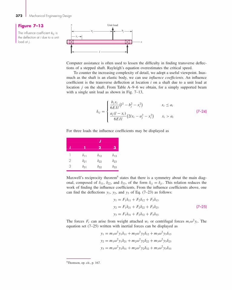
To counter the increasing complexity of detail, we adopt a useful viewpoint. Inas-much as the shaft is an elastic body, we can use influence coefficients. An influencecoefficient is the transverse deflection at location i on a shaft due to a unit load atlocation j on the shaft. From Table A–9–6 we obtain, for a simply supported beamwith a single unit load as shown in Fig. 7–13,
δi j =
⎧⎪⎪⎪⎨⎪⎪⎪⎩bj xi
6E Il
(l2 − b2
j − x2i
)xi ≤ ai
aj (l − xi )
6E Il
(2lxi − a2
j − x2i
)xi > ai
(7–24)
For three loads the influence coefficients may be displayed as
Maxwell’s reciprocity theorem6 states that there is a symmetry about the main diag-onal, composed of δ11, δ22, and δ33, of the form δi j = δj i . This relation reduces thework of finding the influence coefficients. From the influence coefficients above, onecan find the deflections y1, y2, and y3 of Eq. (7–23) as follows:
y1 = F1δ11 + F2δ12 + F3δ13
y2 = F1δ21 + F2δ22 + F3δ23 (7–25)
y3 = F1δ31 + F2δ32 + F3δ33
The forces Fi can arise from weight attached wi or centrifugal forces miω2 yi . The
equation set (7–25) written with inertial forces can be displayed as
y1 = m1ω2 y1δ11 + m2ω
2 y2δ12 + m3ω2 y3δ13
y2 = m1ω2 y1δ21 + m2ω
2 y2δ22 + m3ω2 y3δ23
y3 = m1ω2 y1δ31 + m2ω
2 y2δ32 + m3ω2 y3δ33
J
i 1 2 3
1 δ11 δ12 δ13
2 δ21 δ22 δ23
3 δ31 δ32 δ33
372 Mechanical Engineering Design
aj
l
y
bj
x
xi
Unit loadFigure 7–13
The influence coefficient δi j isthe deflection at i due to a unitload at j.
6Thomson, op. cit., p. 167.
bud21932_ch07_346-394 09/11/2006 05:58 PM Page 372CONFIRMING PAGES

which can be rewritten as
(m1δ11 − 1/ω2)y1 + (m2δ12)y2 + (m3δ13)y3 = 0
(m1δ21)y1 + (m2δ22 − 1/ω2)y2 + (m3δ23)y3 = 0 (a)
(m1δ31)y1 + (m2δ32)y2 + (m3δ33 − 1/ω2)y3 = 0
Equation set (a) is three simultaneous equations in terms of y1, y2, and y3. To avoidthe trivial solution y1 = y2 = y3 = 0, the determinant of the coefficients of y1, y2, andy3 must be zero (eigenvalue problem). Thus,∣∣∣∣∣∣∣
(m1δ11 − 1/ω2) m2δ12 m3δ13
m1δ21 (m2δ22 − 1/ω2) m3δ23
m1δ31 m2δ32 (m3δ33 − 1/ω2)
∣∣∣∣∣∣∣ = 0 (7–26)
which says that a deflection other than zero exists only at three distinct values of ω,the critical speeds. Expanding the determinant, we obtain(
1
ω2
)3
− (m1δ11 + m2δ22 + m3δ33)
(1
ω2
)2
+ · · · = 0 (7–27)
The three roots of Eq. (7–27) can be expressed as 1/ω21 , 1/ω2
2 , and 1/ω23 . Thus
Eq. (7–27) can be written in the form(1
ω2− 1
ω21
)(1
ω2− 1
ω22
)(1
ω2− 1
ω23
)= 0
or (1
ω2
)3
−(
1
ω21
+ 1
ω22
+ 1
ω23
)(1
ω2
)2
+ · · · = 0 (7–28)
Comparing Eqs. (7–27) and (7–28) we see that
1
ω21
+ 1
ω22
+ 1
ω23
= m1δ11 + m2δ22 + m3δ33 (7–29)
If we had only a single mass m1 alone, the critical speed would be given by 1/ω2 =m1δ11. Denote this critical speed as ω11 (which considers only m1 acting alone). Like-wise for m2 or m3 acting alone, we similarly define the terms 1/ω2
22 = m2δ22 or1/ω2
33 = m3δ33, respectively. Thus, Eq. (7–29) can be rewritten as
1
ω21
+ 1
ω22
+ 1
ω23
= 1
ω211
+ 1
ω222
+ 1
ω233
(7–30)
If we order the critical speeds such that ω1 < ω2 < ω3, then 1/ω21 � 1/ω2
2 , and 1/ω23.
So the first, or fundamental, critical speed ω1 can be approximated by
1
ω21
.= 1
ω211
+ 1
ω222
+ 1
ω233
(7–31)
This idea can be extended to an n-body shaft:
1
ω21
.=n∑
1=1
1
ω2i i
(7–32)
Shafts and Shaft Components 373
bud21932_ch07_346-394 09/11/2006 05:58 PM Page 373CONFIRMING PAGES
This is called Dunkerley’s equation. By ignoring the higher mode term(s), the firstcritical speed estimate is lower than actually is the case.
Since Eq. (7–32) has no loads appearing in the equation, it follows that if eachload could be placed at some convenient location transformed into an equivalent load,then the critical speed of an array of loads could be found by summing the equiva-lent loads, all placed at a single convenient location. For the load at station 1, placedat the center of span, denoted with the subscript c, the equivalent load is found from
ω211 = g
w1δ11= g
w1cδcc
or
w1c = w1δ11
δcc(7–33)
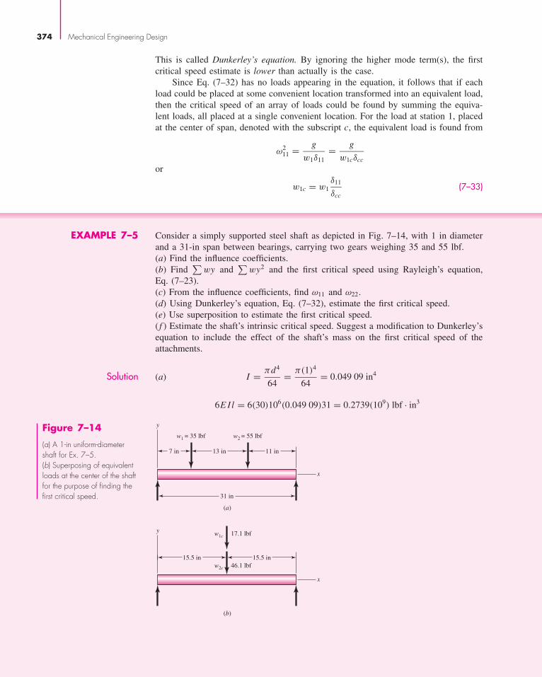
EXAMPLE 7–5 Consider a simply supported steel shaft as depicted in Fig. 7–14, with 1 in diameterand a 31-in span between bearings, carrying two gears weighing 35 and 55 lbf.(a) Find the influence coefficients.(b) Find
∑wy and
∑wy2 and the first critical speed using Rayleigh’s equation,
Eq. (7–23).(c) From the influence coefficients, find ω11 and ω22.(d) Using Dunkerley’s equation, Eq. (7–32), estimate the first critical speed.(e) Use superposition to estimate the first critical speed.( f ) Estimate the shaft’s intrinsic critical speed. Suggest a modification to Dunkerley’sequation to include the effect of the shaft’s mass on the first critical speed of theattachments.
Solution (a) I = πd4
64= π(1)4
64= 0.049 09 in4
6E Il = 6(30)106(0.049 09)31 = 0.2739(109) lbf · in3
374 Mechanical Engineering Design
(a)
x
y
31 in
7 in 13 in
w1 = 35 lbf w2 = 55 lbf
11 in
(b)
x
y17.1 lbfw1c
46.1 lbfw2c
15.5 in 15.5 in
Figure 7–14
(a) A 1-in uniform-diametershaft for Ex. 7–5.(b) Superposing of equivalentloads at the center of the shaftfor the purpose of finding thefirst critical speed.
bud21932_ch07_346-394 09/11/2006 05:58 PM Page 374CONFIRMING PAGES

From Eq. set (7–24),
δ11 = 24(7)(312 − 242 − 72)
0.2739(109)= 2.061(10−4) in/lbf
δ22 = 11(20)(312 − 112 − 202)
0.2739(109)= 3.534(10−4) in/lbf
δ12 = δ21 = 11(7)(312 − 112 − 72)
0.2739(109)= 2.224(10−4) in/lbf
Answer
y1 = w1δ11 + w2δ12 = 35(2.061)10−4 + 55(2.224)10−4 = 0.019 45 in
y2 = w1δ21 + w2δ22 = 35(2.224)10−4 + 55(3.534)10−4 = 0.027 22 in
(b)∑
wi yi = 35(0.019 45) + 55(0.027 22) = 2.178 lbf · in
Answer∑
wi y2i = 35(0.019 45)2 + 55(0.027 22)2 = 0.053 99 lbf · in2
Answer ω =√
386.1(2.178)
0.053 99= 124.8 rad/s , or 1192 rev/min
(c)
Answer1
ω211
= w1
gδ11
ω11 =√
g
w1δ11=
√386.1
35(2.061)10−4= 231.4 rad/s, or 2210 rev/min
Answer ω22 =√
g
w2δ22=
√386.1
55(3.534)10−4= 140.9 rad/s, or 1346 rev/min
(d )1
ω21
.=∑ 1
ω2i i
= 1
231.42+ 1
140.92= 6.905(10−5) (1)
Answer ω1.=
√1
6.905(10−5)= 120.3 rad/s, or 1149 rev/min
which is less than part b, as expected.(e) From Eq. (7–24),
δcc = bccxcc(l2 − b2
cc − x2cc
)6E Il
= 15.5(15.5)(312 − 15.52 − 15.52)
0.2739(109)
= 4.215(10−4) in/lbf
Ji 1 2
1 2.061(10�4) 2.224(10�4)2 2.224(10�4) 3.534(10�4)
Shafts and Shaft Components 375
bud21932_ch07_346-394 09/11/2006 05:58 PM Page 375CONFIRMING PAGES

From Eq. (7–33),
w1c = w1δ11
δcc= 35
2.061(10−4)
4.215(10−4)= 17.11 lbf
w2c = w2δ22
δcc= 55
3.534(10−4)
4.215(10−4)= 46.11 lbf
Answer ω =√
g
δcc∑
wic=
√386.1
4.215(10−4)(17.11 + 46.11)= 120.4 rad/s, or 1150 rev/min
which, except for rounding, agrees with part d, as expected.( f ) For the shaft, E = 30(106) psi, γ = 0.282 lbf/in3, and A = π(12)/4 = 0.7854 in2.Considering the shaft alone, the critical speed, from Eq. (7–22), is
Answer ωs =(
π
l
)2√
gE I
Aγ=
(π
31
)2√
386.1(30)106(0.049 09)
0.7854(0.282)
= 520.4 rad/s, or 4970 rev/min
We can simply add 1/ω2s to the right side of Dunkerley’s equation, Eq. (1), to include
the shaft’s contribution,
Answer1
ω21
.= 1
520.42+ 6.905(10−5) = 7.274(10−5)
ω1.= 117.3 rad/s, or 1120 rev/min
which is slightly less than part d, as expected.The shaft’s first critical speed ωs is just one more single effect to add to Dunker-
ley’s equation. Since it does not fit into the summation, it is usually written up front.
Answer1
ω21
.= 1
ω2s
+n∑
i=1
1
ω2i i
(7–34)
Common shafts are complicated by the stepped-cylinder geometry, which makes theinfluence-coefficient determination part of a numerical solution.
376 Mechanical Engineering Design
7–7 Miscellaneous Shaft Components
SetscrewsUnlike bolts and cap screws, which depend on tension to develop a clamping force, thesetscrew depends on compression to develop the clamping force. The resistance to axialmotion of the collar or hub relative to the shaft is called holding power. This holdingpower, which is really a force resistance, is due to frictional resistance of the contactingportions of the collar and shaft as well as any slight penetration of the setscrew into theshaft.
bud21932_ch07_346-394 09/11/2006 05:58 PM Page 376CONFIRMING PAGES

Figure 7–15 shows the point types available with socket setscrews. These are alsomanufactured with screwdriver slots and with square heads.
Table 7–4 lists values of the seating torque and the corresponding holding powerfor inch-series setscrews. The values listed apply to both axial holding power, for
Shafts and Shaft Components 377
Figure 7–15
Socket setscrews: (a) flat point;(b) cup point; (c) oval point;(d) cone point; (e) half-dogpoint. (a)
L
D
T
(c)
L
D
T
(b)
L
D
T
(d)
L
D
T
(e)
L
D P
T
Table 7–4
Typical Holding Power(Force) for SocketSetscrews*Source: Unbrako Division, SPSTechnologies, Jenkintown, Pa.
Seating HoldingSize, Torque, Power,
in lbf . in lbf
#0 1.0 50#1 1.8 65#2 1.8 85#3 5 120#4 5 160#5 10 200#6 10 250#8 20 385
#10 36 54014 87 10005
16 165 150038 290 20007
16 430 250012 620 30009
16 620 350058 1325 400034 2400 500078 5200 6000
1 7200 7000
*Based on alloy-steel screw against steel shaft, class 3A coarse orfine threads in class 2B holes, and cup-point socket setscrews.
bud21932_ch07_346-394 09/11/2006 05:58 PM Page 377CONFIRMING PAGES

resisting thrust, and the tangential holding power, for resisting torsion. Typical factorsof safety are 1.5 to 2.0 for static loads and 4 to 8 for various dynamic loads.
Setscrews should have a length of about half of the shaft diameter. Note that thispractice also provides a rough rule for the radial thickness of a hub or collar.
Keys and PinsKeys and pins are used on shafts to secure rotating elements, such as gears, pulleys,or other wheels. Keys are used to enable the transmission of torque from the shaft tothe shaft-supported element. Pins are used for axial positioning and for the transferof torque or thrust or both.
Figure 7–16 shows a variety of keys and pins. Pins are useful when the princi-pal loading is shear and when both torsion and thrust are present. Taper pins are sizedaccording to the diameter at the large end. Some of the most useful sizes of these arelisted in Table 7–5. The diameter at the small end is
d = D − 0.0208L (7–35)
where d � diameter at small end, in
D � diameter at large end, in
L � length, in
378 Mechanical Engineering Design
Figure 7–16
(a) Square key; (b) round key;(c and d) round pins; (e) taperpin; (f ) split tubular spring pin.The pins in parts (e) and(f ) are shown longer thannecessary, to illustrate thechamfer on the ends, but theirlengths should be kept smallerthan the hub diameters toprevent injuries due toprojections on rotating parts.
(a) (b) (c)
(d ) (e) ( f )
Commercial PrecisionSize Maximum Minimum Maximum Minimum
4/0 0.1103 0.1083 0.1100 0.10902/0 0.1423 0.1403 0.1420 0.1410
0 0.1573 0.1553 0.1570 0.15602 0.1943 0.1923 0.1940 0.19304 0.2513 0.2493 0.2510 0.25006 0.3423 0.3403 0.3420 0.34108 0.4933 0.4913 0.4930 0.4920
Table 7–5
Dimensions at Large Endof Some Standard TaperPins—Inch Series
bud21932_ch07_346-394 09/11/2006 05:58 PM Page 378CONFIRMING PAGES

For less important applications, a dowel pin or a drive pin can be used. A largevariety of these are listed in manufacturers’ catalogs.7
The square key, shown in Fig. 7–16a, is also available in rectangular sizes. Stan-dard sizes of these, together with the range of applicable shaft diameters, are listed inTable 7–6. The shaft diameter determines standard sizes for width, height, and key depth.The designer chooses an appropriate key length to carry the torsional load. Failure ofthe key can be by direct shear, or by bearing stress. Example 7–6 demonstrates theprocess to size the length of a key. The maximum length of a key is limited by the hublength of the attached element, and should generally not exceed about 1.5 times theshaft diameter to avoid excessive twisting with the angular deflection of the shaft. Mul-tiple keys may be used as necessary to carry greater loads, typically oriented at 90
ofrom
one another. Excessive safety factors should be avoided in key design, since it is desir-able in an overload situation for the key to fail, rather than more costly components.
Stock key material is typically made from low carbon cold-rolled steel, and ismanufactured such that its dimensions never exceed the nominal dimension. Thisallows standard cutter sizes to be used for the keyseats. A setscrew is sometimes usedalong with a key to hold the hub axially, and to minimize rotational backlash whenthe shaft rotates in both directions.
Shafts and Shaft Components 379
Table 7–6
Inch Dimensions forSome Standard Square-and Rectangular-KeyApplicationsSource: Joseph E. Shigley,“Unthreaded Fasteners,”Chap. 24 in Joseph E.Shigley, Charles R. Mischke,and Thomas H. Brown, Jr.(eds.), Standard Handbook ofMachine Design, 3rd ed.,McGraw-Hill, New York,2004.
Shaft Diameter Key SizeOver To (Incl.) w h Keyway Depth
516
716
332
332
364
716
916
18
332
364
18
18
116
916
78
316
18
116
316
316
332
78 1 1
414
316
332
14
14
18
1 14 1 3
85
1614
18
516
516
532
1 38 1 3
438
14
18
38
38
316
1 34 2 1
412
38
316
12
12
14
2 14 2 3
458
716
732
58
58
516
2 34 3 1
434
12
14
34
34
38
7See also Joseph E. Shigley, “Unthreaded Fasteners,” Chap. 24. In Joseph E. Shigley, Charles R. Mischke, andThomas H. Brown, Jr. (eds.), Standard Handbook of Machine Design, 3rd ed., McGraw-Hill, New York, 2004.
bud21932_ch07_346-394 09/11/2006 05:58 PM Page 379CONFIRMING PAGES

The gib-head key, in Fig. 7–17a, is tapered so that, when firmly driven, it acts toprevent relative axial motion. This also gives the advantage that the hub position canbe adjusted for the best axial location. The head makes removal possible withoutaccess to the other end, but the projection may be hazardous.
The Woodruff key, shown in Fig. 7–17b, is of general usefulness, especially when awheel is to be positioned against a shaft shoulder, since the keyslot need not be machinedinto the shoulder stress-concentration region. The use of the Woodruff key also yieldsbetter concentricity after assembly of the wheel and shaft. This is especially important athigh speeds, as, for example, with a turbine wheel and shaft. Woodruff keys are partic-ularly useful in smaller shafts where their deeper penetration helps prevent key rolling.Dimensions for some standard Woodruff key sizes can be found in Table 7–7, and Table7–8 gives the shaft diameters for which the different keyseat widths are suitable.
Pilkey8 gives values for stress concentrations in an end-milled keyseat, as a func-tion of the ratio of the radius r at the bottom of the groove and the shaft diameter d.For fillets cut by standard milling-machine cutters, with a ratio of r/d = 0.02,Peterson’s charts give Kt = 2.14 for bending and Kts = 2.62 for torsion without thekey in place, or Kts = 3.0 for torsion with the key in place. The stress concentrationat the end of the keyseat can be reduced somewhat by using a sled-runner keyseat,eliminating the abrupt end to the keyseat, as shown in Fig. 7–17. It does, however,still have the sharp radius in the bottom of the groove on the sides. The sled-runnerkeyseat can only be used when definite longitudinal key positioning is not necessary.It is also not as suitable near a shoulder. Keeping the end of a keyseat at least a distance
380 Mechanical Engineering Design
Figure 7–17
(a) Gib-head key;(b) Woodruff key.
Taper in 12""
(a)
(b)
w w
w
D
h
1
8
8W. D. Pilkey, Peterson’s Stress Concentration Factors, 2nd ed., John Wiley & Sons, New York, 1997, pp. 408–409.
bud21932_ch07_346-394 09/11/2006 05:58 PM Page 380CONFIRMING PAGES

Shafts and Shaft Components 381
Table 7–7
Dimensions of WoodruffKeys—Inch Series
Key Size Height Offset Keyseat Depthw D b e Shaft Hub116
14 0.109 1
64 0.0728 0.0372116
38 0.172 1
64 0.1358 0.0372332
38 0.172 1
64 0.1202 0.0529332
12 0.203 3
64 0.1511 0.0529332
58 0.250 1
16 0.1981 0.052918
12 0.203 3
64 0.1355 0.068518
58 0.250 1
16 0.1825 0.068518
34 0.313 1
16 0.2455 0.0685532
58 0.250 1
16 0.1669 0.0841532
34 0.313 1
16 0.2299 0.0841532
78 0.375 1
16 0.2919 0.0841316
34 0.313 1
16 0.2143 0.0997316
78 0.375 1
16 0.2763 0.0997316 1 0.438 1
16 0.3393 0.099714
78 0.375 1
16 0.2450 0.131014 1 0.438 1
16 0.3080 0.131014 11
4 0.547 564 0.4170 0.1310
516 1 0.438 1
16 0.2768 0.1622516 11
4 0.547 564 0.3858 0.1622
516 11
2 0.641 764 0.4798 0.1622
38 11
4 0.547 564 0.3545 0.1935
38 11
2 0.641 764 0.4485 0.1935
Keyseat Shaft Diameter, inWidth, in From To (inclusive)
116
516
12
332
38
78
18
38 11
2532
12 15
8316
916 2
14
1116 21
4516
34 23
838 1 25
8
Table 7–8
Sizes of Woodruff KeysSuitable for VariousShaft Diameters
bud21932_ch07_346-394 09/11/2006 05:58 PM Page 381CONFIRMING PAGES
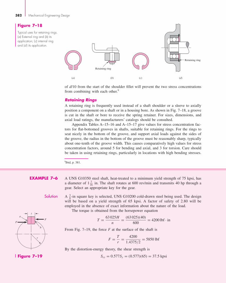
Figure 7–18
Typical uses for retaining rings.(a) External ring and (b) itsapplication; (c) internal ringand (d ) its application.
Retaining ring
(a) (c) (d)(b)
Retaining ring
of d/10 from the start of the shoulder fillet will prevent the two stress concentrationsfrom combining with each other.9
Retaining RingsA retaining ring is frequently used instead of a shaft shoulder or a sleeve to axiallyposition a component on a shaft or in a housing bore. As shown in Fig. 7–18, a grooveis cut in the shaft or bore to receive the spring retainer. For sizes, dimensions, andaxial load ratings, the manufacturers’ catalogs should be consulted.
Appendix Tables A–15–16 and A–15–17 give values for stress concentration fac-tors for flat-bottomed grooves in shafts, suitable for retaining rings. For the rings toseat nicely in the bottom of the groove, and support axial loads against the sides ofthe groove, the radius in the bottom of the groove must be reasonably sharp, typicallyabout one-tenth of the groove width. This causes comparatively high values for stressconcentration factors, around 5 for bending and axial, and 3 for torsion. Care shouldbe taken in using retaining rings, particularly in locations with high bending stresses.
382 Mechanical Engineering Design
Figure 7–19
t
b
FF
r
a
9Ibid, p. 381.
EXAMPLE 7–6 A UNS G10350 steel shaft, heat-treated to a minimum yield strength of 75 kpsi, hasa diameter of 1 7
16 in. The shaft rotates at 600 rev/min and transmits 40 hp through agear. Select an appropriate key for the gear.
Solution A 38 -in square key is selected, UNS G10200 cold-drawn steel being used. The design
will be based on a yield strength of 65 kpsi. A factor of safety of 2.80 will beemployed in the absence of exact information about the nature of the load.
The torque is obtained from the horsepower equation
T = 63 025H
n= (63 025)(40)
600= 4200 lbf · in
From Fig. 7–19, the force F at the surface of the shaft is
F = T
r= 4200
1.4375/2= 5850 lbf
By the distortion-energy theory, the shear strength is
Ssy = 0.577Sy = (0.577)(65) = 37.5 kpsi
bud21932_ch07_346-394 09/11/2006 05:58 PM Page 382CONFIRMING PAGES

Failure by shear across the area ab will create a stress of τ = F/tl . Substituting thestrength divided by the factor of safety for τ gives
Ssy
n= F
tlor
37.5(10)3
2.80= 5850
0.375l
or l = 1.16 in. To resist crushing, the area of one-half the face of the key is used:
Sy
n= F
tl/2or
65(10)3
2.80= 5850
0.375l/2
and l = 1.34 in. The hub length of a gear is usually greater than the shaft diameter,for stability. If the key, in this example, is made equal in length to the hub, it wouldtherefore have ample strength, since it would probably be 1 7
16 in or longer.
Shafts and Shaft Components 383
10Preferred Limits and Fits for Cylindrical Parts, ANSI B4.1-1967. Preferred Metric Limits and Fits, ANSIB4.2-1978.
7–8 Limits and FitsThe designer is free to adopt any geometry of fit for shafts and holes that will ensurethe intended function. There is sufficient accumulated experience with commonly recur-ring situations to make standards useful. There are two standards for limits and fits inthe United States, one based on inch units and the other based on metric units.10 Thesediffer in nomenclature, definitions, and organization. No point would be served by sep-arately studying each of the two systems. The metric version is the newer of the twoand is well organized, and so here we present only the metric version but include a setof inch conversions to enable the same system to be used with either system of units.
In using the standard, capital letters always refer to the hole; lowercase lettersare used for the shaft.
The definitions illustrated in Fig. 7–20 are explained as follows:
• Basic size is the size to which limits or deviations are assigned and is the same forboth members of the fit.
• Deviation is the algebraic difference between a size and the corresponding basic size.
• Upper deviation is the algebraic difference between the maximum limit and thecorresponding basic size.
• Lower deviation is the algebraic difference between the minimum limit and thecorresponding basic size.
• Fundamental deviation is either the upper or the lower deviation, depending onwhich is closer to the basic size.
• Tolerance is the difference between the maximum and minimum size limits of a part.
• International tolerance grade numbers (IT) designate groups of tolerances such thatthe tolerances for a particular IT number have the same relative level of accuracybut vary depending on the basic size.
• Hole basis represents a system of fits corresponding to a basic hole size. The fun-damental deviation is H.
bud21932_ch07_346-394 09/11/2006 05:58 PM Page 383CONFIRMING PAGES

• Shaft basis represents a system of fits corresponding to a basic shaft size. Thefundamental deviation is h. The shaft-basis system is not included here.
The magnitude of the tolerance zone is the variation in part size and is the samefor both the internal and the external dimensions. The tolerance zones are specifiedin international tolerance grade numbers, called IT numbers. The smaller grade num-bers specify a smaller tolerance zone. These range from IT0 to IT16, but only gradesIT6 to IT11 are needed for the preferred fits. These are listed in Tables A–11 to A–13for basic sizes up to 16 in or 400 mm.
The standard uses tolerance position letters, with capital letters for internal dimen-sions (holes) and lowercase letters for external dimensions (shafts). As shown in Fig. 7–20,the fundamental deviation locates the tolerance zone relative to the basic size.
Table 7–9 shows how the letters are combined with the tolerance grades to estab-lish a preferred fit. The ISO symbol for the hole for a sliding fit with a basic size of32 mm is 32H7. Inch units are not a part of the standard. However, the designation(1 3
8 in) H7 includes the same information and is recommended for use here. In bothcases, the capital letter H establishes the fundamental deviation and the number 7defines a tolerance grade of IT7.
For the sliding fit, the corresponding shaft dimensions are defined by the symbol32g6 [(1 3
8 in)g6].The fundamental deviations for shafts are given in Tables A–11 and A–13. For
letter codes c, d, f, g, and h,
Upper deviation = fundamental deviationLower deviation = upper deviation − tolerance grade
For letter codes k, n, p, s, and u, the deviations for shafts are
Lower deviation = fundamental deviationUpper deviation = lower deviation + tolerance grade
384 Mechanical Engineering Design
Max. size, dmax
Min. size, dmin
Basic size, D(d)
Max. size, Dmax
Upper deviation, �u
Lower deviation, �l
International tolerance
grade, � d (IT number)
Fundamental deviation,
�F (letter)
Lower deviation, �l
Upper deviation, �u
Min. size, Dmin
Fundamental deviation,
�F (letter)International tolerance
grade, � D (IT number)
Figure 7–20
Definitions applied to acylindrical fit.
bud21932_ch07_346-394 09/11/2006 05:58 PM Page 384CONFIRMING PAGES

The lower deviation H (for holes) is zero. For these, the upper deviation equals thetolerance grade.
As shown in Fig. 7–20, we use the following notation:
Note that these quantities are all deterministic. Thus, for the hole,
Dmax = D + D Dmin = D (7–36)
For shafts with clearance fits c, d, f, g, and h,
dmax = d + δF dmin = d + δF − d (7–37)
For shafts with interference fits k, n, p, s, and u,
dmin = d + δF dmax = d + δF + d (7–38)
D = basic size of holed = basic size of shaft
δu = upper deviationδl = lower deviationδF = fundamental deviation
D = tolerance grade for holed = tolerance grade for shaft
Shafts and Shaft Components 385
Table 7–9
Descriptions of PreferredFits Using the BasicHole SystemSource: Preferred Metric Limitsand Fits, ANSI B4.2-1978.See also BS 4500.
Type of Fit Description Symbol
Clearance Loose running fit: for wide commercial tolerances or H11/c11allowances on external membersFree running fit: not for use where accuracy is H9/d9essential, but good for large temperature variations,high running speeds, or heavy journal pressuresClose running fit: for running on accurate machines H8/f7and for accurate location at moderate speeds and journal pressuresSliding fit: where parts are not intended to run freely, H7/g6but must move and turn freely and locate accuratelyLocational clearance fit: provides snug fit for location H7/h6of stationary parts, but can be freely assembled and disassembled
Transition Locational transition fit for accurate location, a H7/k6compromise between clearance and interferenceLocational transition fit for more accurate location H7/n6where greater interference is permissible
Interference Locational interference fit: for parts requiring rigidity H7/p6and alignment with prime accuracy of location butwithout special bore pressure requirementsMedium drive fit: for ordinary steel parts or shrink fits on H7/s6light sections, the tightest fit usable with cast ironForce fit: suitable for parts that can be highly stressed H7/u6or for shrink fits where the heavy pressing forces requiredare impractical
bud21932_ch07_346-394 09/11/2006 05:58 PM Page 385CONFIRMING PAGES

EXAMPLE 7–7 Find the shaft and hole dimensions for a loose running fit with a 34-mm basic size.
Solution From Table 7–9, the ISO symbol is 34H11/c11. From Table A–11, we find that tol-erance grade IT11 is 0.160 mm. The symbol 34H11/c11 therefore says thatD = d = 0.160 mm. Using Eq. (7–36) for the hole, we get
Answer Dmax = D + D = 34 + 0.160 = 34.160 mm
Answer Dmin = D = 34.000 mm
The shaft is designated as a 34c11 shaft. From Table A–12, the fundamental devia-tion is δF = −0.120 mm. Using Eq. (7–37), we get for the shaft dimensions
Answer dmax = d + δF = 34 + (−0.120) = 33.880 mm
Answer dmin = d + δF − d = 34 + (−0.120) − 0.160 = 33.720 mm
386 Mechanical Engineering Design
EXAMPLE 7–8 Find the hole and shaft limits for a medium drive fit using a basic hole size of 2 in.
Solution The symbol for the fit, from Table 7–8, in inch units is (2 in)H7/s6. For the hole, weuse Table A–13 and find the IT7 grade to be D = 0.0010 in. Thus, from Eq. (7–36),
Answer Dmax = D + D = 2 + 0.0010 = 2.0010 in
Answer Dmin = D = 2.0000 in
The IT6 tolerance for the shaft is d = 0.0006 in. Also, from Table A–14, thefundamental deviation is δF = 0.0017 in. Using Eq. (7–38), we get for the shaft that
Answer dmin = d + δF = 2 + 0.0017 = 2.0017 in
Answer dmax = d + δF + d = 2 + 0.0017 + 0.0006 = 2.0023 in
Stress and Torque Capacity in Interference FitsInterference fits between a shaft and its components can sometimes be used effec-tively to minimize the need for shoulders and keyways. The stresses due to an inter-ference fit can be obtained by treating the shaft as a cylinder with a uniform externalpressure, and the hub as a hollow cylinder with a uniform internal pressure. Stressequations for these situations were developed in Sec. 3–16, and will be converted herefrom radius terms into diameter terms to match the terminology of this section.
bud21932_ch07_346-394 09/11/2006 05:58 PM Page 386CONFIRMING PAGES

The pressure p generated at the interface of the interference fit, from Eq. (3–56)converted into terms of diameters, is given by
p = δ
d
Eo
(d2
o + d2
d2o − d2
+ νo
)+ d
Ei
(d2 + d2
i
d2 − d2i
− νi
) (7–39)
or, in the case where both members are of the same material,
p = Eδ
2d3
[(d2
o − d2)(d2 − d2i )
d2o − d2
i
](7–40)
where d is the nominal shaft diameter, di is the inside diameter (if any) of the shaft,do is the outside diameter of the hub, E is Young’s modulus, and v is Poisson’s ratio,with subscripts o and i for the outer member (hub) and inner member (shaft), respec-tively. δ is the diametral interference between the shaft and hub, that is, the differ-ence between the shaft outside diameter and the hub inside diameter.
δ = dshaft − dhub (7–41)
Since there will be tolerances on both diameters, the maximum and minimumpressures can be found by applying the maximum and minimum interferences. Adopt-ing the notation from Fig. 7–20, we write
δmin = dmin − Dmax (7–42)
δmax = dmax − Dmin (7–43)
where the diameter terms are defined in Eqs. (7–36) and (7–38). The maximum inter-ference should be used in Eq. (7–39) or (7–40) to determine the maximum pressureto check for excessive stress.
From Eqs. (3–58) and (3–59), with radii converted to diameters, the tangentialstresses at the interface of the shaft and hub are
σt, shaft = −pd2 + di
2
d2 − di2
(7–44)
σt, hub = pdo
2 + d2
do2 − d2
(7–45)
The radial stresses at the interface are simply
σr, shaft = −p (7–46)
σr, hub = −p (7–47)
The tangential and radial stresses are orthogonal, and should be combined using afailure theory to compare with the yield strength. If either the shaft or hub yields dur-ing assembly, the full pressure will not be achieved, diminishing the torque that can betransmitted. The interaction of the stresses due to the interference fit with the otherstresses in the shaft due to shaft loading is not trivial. Finite-element analysis of theinterface would be appropriate when warranted. A stress element on the surface of arotating shaft will experience a completely reversed bending stress in the longitudinaldirection, as well as the steady compressive stresses in the tangential and radial direc-tions. This is a three-dimensional stress element. Shear stress due to torsion in shaftmay also be present. Since the stresses due to the press fit are compressive, the fatiguesituation is usually actually improved. For this reason, it may be acceptable to simplify
Shafts and Shaft Components 387
bud21932_ch07_346-394 09/11/2006 05:58 PM Page 387CONFIRMING PAGES
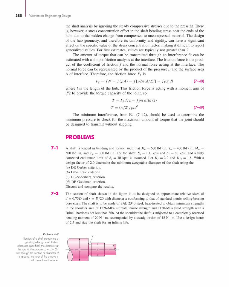
the shaft analysis by ignoring the steady compressive stresses due to the press fit. Thereis, however, a stress concentration effect in the shaft bending stress near the ends of thehub, due to the sudden change from compressed to uncompressed material. The designof the hub geometry, and therefore its uniformity and rigidity, can have a significanteffect on the specific value of the stress concentration factor, making it difficult to reportgeneralized values. For first estimates, values are typically not greater than 2.
The amount of torque that can be transmitted through an interference fit can beestimated with a simple friction analysis at the interface. The friction force is the prod-uct of the coefficient of friction f and the normal force acting at the interface. Thenormal force can be represented by the product of the pressure p and the surface areaA of interface. Therefore, the friction force Ff is
Ff = f N = f (p A) = f [p2π(d/2)l] = f pπ dl (7–48)
where l is the length of the hub. This friction force is acting with a moment arm ofd/2 to provide the torque capacity of the joint, so
T = Ff d/2 = f pπ dl(d/2)
T = (π/2) f pld2 (7–49)
The minimum interference, from Eq. (7–42), should be used to determine theminimum pressure to check for the maximum amount of torque that the joint shouldbe designed to transmit without slipping.
PROBLEMS
7–1 A shaft is loaded in bending and torsion such that Ma = 600 lbf · in, Ta = 400 lbf · in, Mm =500 lbf · in, and Tm = 300 lbf · in. For the shaft, Su = 100 kpsi and Sy = 80 kpsi, and a fullycorrected endurance limit of Se = 30 kpsi is assumed. Let K f = 2.2 and K f s = 1.8. With adesign factor of 2.0 determine the minimum acceptable diameter of the shaft using the(a) DE-Gerber criterion.(b) DE-elliptic criterion.(c) DE-Soderberg criterion.(d ) DE-Goodman criterion.Discuss and compare the results.
7–2 The section of shaft shown in the figure is to be designed to approximate relative sizes ofd = 0.75D and r = D/20 with diameter d conforming to that of standard metric rolling-bearingbore sizes. The shaft is to be made of SAE 2340 steel, heat-treated to obtain minimum strengthsin the shoulder area of 1226-MPa ultimate tensile strength and 1130-MPa yield strength with aBrinell hardness not less than 368. At the shoulder the shaft is subjected to a completely reversedbending moment of 70 N · m, accompanied by a steady torsion of 45 N · m. Use a design factorof 2.5 and size the shaft for an infinite life.
388 Mechanical Engineering Design
r
D d
Problem 7–2Section of a shaft containing a
grinding-relief groove. Unlessotherwise specified, the diameter atthe root of the groove dr = d − 2r,
and though the section of diameter dis ground, the root of the groove is
still a machined surface.
bud21932_ch07_346-394 09/11/2006 05:58 PM Page 388CONFIRMING PAGES

7–3 The rotating solid steel shaft is simply supported by bearings at points B and C and is drivenby a gear (not shown) which meshes with the spur gear at D, which has a 6-in pitch diameter.The force F from the drive gear acts at a pressure angle of 20
o. The shaft transmits a torque
to point A of TA = 3000 lbf · in. The shaft is machined from steel with Sy = 60 kpsi andSut = 80 kpsi. Using a factor of safety of 2.5, determine the minimum allowable diameter ofthe 10 in section of the shaft based on (a) a static yield analysis using the distortion energytheory and (b) a fatigue-failure analysis. Assume sharp fillet radii at the bearing shoulders forestimating stress concentration factors.
Shafts and Shaft Components 389
10 in
4 in
A
TA
B
C
F
20�
D
Problem 7–3
Gear 4
3 dia.
x
F
B
A
y
O
z 20°
4 dia.
1
8
2
3
2
3
4
13
4
3
4
Problem 7–4Material moves under the roll.
Dimensions in inches.
7–5 Design a shaft for the situation of the industrial roll of Prob. 7–4 with a design factor of 2 anda reliability goal of 0.999 against fatigue failure. Plan for a ball bearing on the left and a cylin-drical roller on the right. For deformation use a factor of safety of 2.
7–4 A geared industrial roll shown in the figure is driven at 300 rev/min by a force F acting on a3-in-diameter pitch circle as shown. The roll exerts a normal force of 30 lbf/in of roll lengthon the material being pulled through. The material passes under the roll. The coefficient of fric-tion is 0.40. Develop the moment and shear diagrams for the shaft modeling the roll force as(a) a concentrated force at the center of the roll, and (b) a uniformly distributed force alongthe roll. These diagrams will appear on two orthogonal planes.
bud21932_ch07_346-394 09/11/2006 05:58 PM Page 389CONFIRMING PAGES

7–6 The figure shows a proposed design for the industrial roll shaft of Prob. 7–4. Hydrodynamic filmbearings are to be used. All surfaces are machined except the journals, which are ground and pol-ished. The material is 1035 HR steel. Perform a design assessment. Is the design satisfactory?
390 Mechanical Engineering Design
10 4
1 keyway
1
1
O A
7
8
1
1
21
1
2
1
4
1
4
Problem 7–6Bearing shoulder fillets 0.030 in,
others 116 in. Sled-runner keyway is
312 in long. Dimensions in inches.
7–7 In the double-reduction gear train shown, shaft a is driven by a motor attached by a flexiblecoupling attached to the overhang. The motor provides a torque of 2500 lbf · in at a speed of1200 rpm. The gears have 20o pressure angles, with diameters shown on the figure. Use anAISI 1020 cold-drawn steel. Design one of the shafts (as specified by the instructor) with adesign factor of 1.5 by performing the following tasks.(a) Sketch a general shaft layout, including means to locate the gears and bearings, and to trans-
mit the torque.(b) Perform a force analysis to find the bearing reaction forces, and generate shear and bend-
ing moment diagrams.(c) Determine potential critical locations for stress design.(d) Determine critical diameters of the shaft based on fatigue and static stresses at the critical
locations.(e) Make any other dimensional decisions necessary to specify all diameters and axial dimen-
sions. Sketch the shaft to scale, showing all proposed dimensions.(f) Check the deflection at the gear, and the slopes at the gear and the bearings for satisfaction
of the recommended limits in Table 7–2.(g) If any of the deflections exceed the recommended limits, make appropriate changes to bring
them all within the limits.
83
16
20
24
E
C
A B
D
Fc
b
a
12 9 62
8
4
Problem 7–7Dimensions in inches.
7–8 In the figure is a proposed shaft design to be used for the input shaft a in Prob. 7–7. A ballbearing is planned for the left bearing, and a cylindrical roller bearing for the right.(a) Determine the minimum fatigue factor of safety by evaluating at any critical locations. Use a
fatigue failure criteria that is considered to be typical of the failure data, rather than one thatis considered conservative. Also ensure that the shaft does not yield in the first load cycle.
bud21932_ch07_346-394 09/11/2006 05:58 PM Page 390CONFIRMING PAGES
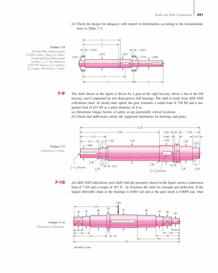
(b) Check the design for adequacy with respect to deformation, according to the recommenda-tions in Table 7–2.
Shafts and Shaft Components 391
155
30 3020
30
6085
150
375
35
30
55115
All fillets 2 mm
10
3540 4055
45
7 kN
Problem 7–10Dimensions in millimeters.
7–10 An AISI 1020 cold-drawn steel shaft with the geometry shown in the figure carries a transverseload of 7 kN and a torque of 107 N · m. Examine the shaft for strength and deflection. If thelargest allowable slope at the bearings is 0.001 rad and at the gear mesh is 0.0005 rad, what
7
8
0.354
1.5741.875
9
11 6
1.5001.574
0.453
1.875
3
4Problem 7–8
Shoulder fillets at bearing seat0.030-in radius, others 1
8 -in radius,except right-hand bearing seattransition, 1
4 in. The material is1030 HR. Keyways 3
8 in wide by316 in deep. Dimensions in inches.
12.87
8.50
2.75
2.0 1.181 1.70
1.000
keyway× 0.1 R.
2.0
1.750
0.485
0.20
1.40
2.20
0.75
1.181
0.151
4
1
8
1
16 R.
1
32 R.1
32 R.
1
8 R.
keyway×3
8
3
16
1
8 R.
Problem 7–9Dimensions in inches.
7–9 The shaft shown in the figure is driven by a gear at the right keyway, drives a fan at the leftkeyway, and is supported by two deep-groove ball bearings. The shaft is made from AISI 1020cold-drawn steel. At steady-state speed, the gear transmits a radial load of 230 lbf and a tan-gential load of 633 lbf at a pitch diameter of 8 in.(a) Determine fatigue factors of safety at any potentially critical locations.(b) Check that deflections satisfy the suggested minimums for bearings and gears.
bud21932_ch07_346-394 09/11/2006 05:58 PM Page 391CONFIRMING PAGES

7–12 A heat-treated steel shaft is to be designed to support the spur gear and the overhanging wormshown in the figure. A bearing at A takes pure radial load. The bearing at B takes the worm-thrust load for either direction of rotation. The dimensions and the loading are shown in thefigure; note that the radial loads are in the same plane. Make a complete design of the shaft,including a sketch of the shaft showing all dimensions. Identify the material and its heat treat-ment (if necessary). Provide an assessment of your final design. The shaft speed is 310 rev/min.
392 Mechanical Engineering Design
44
4
RA RB
RB
T
600 lbf
14 3
950 lbf
5600 lbf
T = 4800 lbf-in
A B
Problem 7–12Dimensions in inches.
7
CL brg CL brg
16 5
2
4
BA
Problem 7–11Dimensions in inches.
is the factor of safety guarding against damaging distortion? What is the factor of safety guard-ing against a fatigue failure? If the shaft turns out to be unsatisfactory, what would you rec-ommend to correct the problem?
7–11 A shaft is to be designed to support the spur pinion and helical gear shown in the figure ontwo bearings spaced 28 in center-to-center. Bearing A is a cylindrical roller and is to take onlyradial load; bearing B is to take the thrust load of 220 lbf produced by the helical gear and itsshare of the radial load. The bearing at B can be a ball bearing. The radial loads of both gearsare in the same plane, and are 660 lbf for the pinion and 220 lbf for the gear. The shaft speedis 1150 rev/min. Design the shaft. Make a sketch to scale of the shaft showing all fillet sizes,keyways, shoulders, and diameters. Specify the material and its heat treatment.
7–13 A bevel-gear shaft mounted on two 40-mm 02-series ball bearings is driven at 1720 rev/minby a motor connected through a flexible coupling. The figure shows the shaft, the gear, and thebearings. The shaft has been giving trouble—in fact, two of them have already failed—and thedown time on the machine is so expensive that you have decided to redesign the shaft your-self rather than order replacements. A hardness check of the two shafts in the vicinity of the frac-ture of the two shafts showed an average of 198 Bhn for one and 204 Bhn of the other. As closelyas you can estimate the two shafts failed at a life measure between 600 000 and 1 200 000 cycles
bud21932_ch07_346-394 09/11/2006 05:58 PM Page 392CONFIRMING PAGES
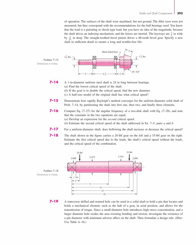
of operation. The surfaces of the shaft were machined, but not ground. The fillet sizes were notmeasured, but they correspond with the recommendations for the ball bearings used. You knowthat the load is a pulsating or shock-type load, but you have no idea of the magnitude, becausethe shaft drives an indexing mechanism, and the forces are inertial. The keyways are 3
8 in wideby 3
16 in deep. The straight-toothed bevel pinion drives a 48-tooth bevel gear. Specify a newshaft in sufficient detail to ensure a long and trouble-free life.
1
2Shaft failed here
4P, 16T4 26
1
2
1
2 dia.13
8 dia.
Problem 7–13Dimensions in inches.
2.000 2.0002.472
1
2
9
14
15
16
2.763
35 lbf20 lbf
Problem 7–18Dimensions in inches.
Shafts and Shaft Components 393
7–19 A transverse drilled and reamed hole can be used in a solid shaft to hold a pin that locates andholds a mechanical element, such as the hub of a gear, in axial position, and allows for thetransmission of torque. Since a small-diameter hole introduces high stress concentration, and alarger diameter hole erodes the area resisting bending and torsion, investigate the existence ofa pin diameter with minimum adverse affect on the shaft. Then formulate a design rule. (Hint:Use Table A–16.)
7–14 A 1-in-diameter uniform steel shaft is 24 in long between bearings.(a) Find the lowest critical speed of the shaft.(b) If the goal is to double the critical speed, find the new diameter.(c) A half-size model of the original shaft has what critical speed?
7–15 Demonstrate how rapidly Rayleigh’s method converges for the uniform-diameter solid shaft ofProb. 7–14, by partitioning the shaft into first one, then two, and finally three elements.
7–16 Compare Eq. (7–27) for the angular frequency of a two-disk shaft with Eq. (7–28), and notethat the constants in the two equations are equal.(a) Develop an expression for the second critical speed.(b) Estimate the second critical speed of the shaft addressed in Ex. 7–5, parts a and b.
7–17 For a uniform-diameter shaft, does hollowing the shaft increase or decrease the critical speed?
7–18 The shaft shown in the figure carries a 20-lbf gear on the left and a 35-lbf gear on the right.Estimate the first critical speed due to the loads, the shaft’s critical speed without the loads,and the critical speed of the combination.
bud21932_ch07_346-394 09/11/2006 05:58 PM Page 393CONFIRMING PAGES

7–20 A guide pin is required to align the assembly of a two-part fixture. The nominal size of the pinis 15 mm. Make the dimensional decisions for a 15-mm basic size locational clearance fit.
7–21 An interference fit of a cast-iron hub of a gear on a steel shaft is required. Make the dimen-sional decisions for a 45-mm basic size medium drive fit.
7–22 A pin is required for forming a linkage pivot. Find the dimensions required for a 50-mm basicsize pin and clevis with a sliding fit.
7–23 A journal bearing and bushing need to be described. The nominal size is 1 in. What dimen-sions are needed for a 1-in basic size with a close running fit if this is a lightly loaded journaland bushing assembly?
7–24 A gear and shaft with nominal diameter of 1.5 in are to be assembled with a medium drive fit,as specified in Table 7–9. The gear has a hub, with an outside diameter of 2.5 in, and an over-all length of 2 in. The shaft is made from AISI 1020 CD steel, and the gear is made from steelthat has been through hardened to provide Su � 100 kpsi and Sy � 85 kpsi.(a) Specify dimensions with tolerances for the shaft and gear bore to achieve the desired fit.(b) Determine the minimum and maximum pressures that could be experienced at the interface
with the specified tolerances.(c) Determine the worst-case static factors of safety guarding against yielding at assembly for
the shaft and the gear based on the distortion energy failure theory.(d ) Determine the maximum torque that the joint should be expected to transmit without slip-
ping, i.e., when the interference pressure is at a minimum for the specified tolerances.
394 Mechanical Engineering Design
bud21932_ch07_346-394 09/11/2006 05:58 PM Page 394CONFIRMING PAGES