Embed Size (px)
Citation preview
International Journal of Science and Research (IJSR) ISSN: 2319-7064
ResearchGate Impact Factor (2018): 0.28 | SJIF (2018): 7.426
Volume 8 Issue 4, April 2019
www.ijsr.net Licensed Under Creative Commons Attribution CC BY
Design of MBBR Based Sewage Treatment Plant
for an Educational Campus
Ruksana T P1, Priyanka T
2, Haneesh K R
3
1M Tech Student, Department of Civil Engineering, Cochin College of Engineering and Technology, Kerala, India
2Assistant Professor, Department of Civil Engineering, Cochin College of Engineering and Technology, Kerala, India
3 Research Scholar, School of Environmental Studies, Cochin University of Science and Technology, Cochin, Kerala
Abstract: Waste water reclamation is the treatment or processing of waste water to make it reusable. In educational campuses where
the demand for water is huge, it is highly feasible to adopt a system of waste water recycling for purposes like toilet flushing,
gardening/agriculture and for maintenance of landscape, since these are usages with low physical contact. Among the available
technologies for waste water treatment, MBBR based sewage treatment is most suitable. This paper demonstrates the detailed procedure
for the design of a MBBR based sewage treatment plant of 530 KLD capacity for an educational campus.
Keywords: Sewage treatment, MBBR, Educational campus
1. Introduction
In many locations where the available supply of fresh water
has become inadequate to meet water needs, it is clear that
the once-used water collected from communities and
municipalities must be viewed not as a waste to be disposed
of but as a resource that must be reused [1]. Waste water
reclamation is the treatment or processing of waste water to
make it reusable, and water reuse is the use of treated waste
water for beneficial purposes such as agricultural irrigation
and industrial cooling [2]. The cost of treating 1 KLD (Kilo-
Litre per Day) of sewage is about 18 to 20 INR (Indian
Rupees), while the cost of treated water lies between 40 – 60
INR, thereby posing a profitable option for most citizens
prospectively treating their own water, and fostering a
positive response from a possibly participatory public [3].
Therefore, we must establish technology to recover or
remediate contaminated water for reuse in energy and food
production as well as to become more efficient in its use. [4]
2. Waste Water Treatment Technologies
One of the most challenging aspects of a sustainable sewage
treatment system design (either centralized or decentralized)
is the analysis and selection of the treatment processes and
technologies capable of meeting the requirements. The
process is to be selected based on required quality of treated
water. While treatment costs are important, other factors
should also be given due consideration. For instance, effluent
quality, process complexity, process reliability,
environmental issues and land requirements should be
evaluated and weighted against cost considerations [5]. The
following are the technologies used in sewage treatment.
Activated Sludge Process (ASP)
Moving Bed Bio-film Reactor (MBBR)
Sequencing Batch Reactor (SBR)
Up-flow Anaerobic Sludge Blanket (UASB) Membrane Bio Reactor (MBR)
Among these, MBBR technology is found suitable where the
availability of land area, capital investment and skilled
manpower for operation and maintenance are scarce [6].
3. MBBR – An Overview
Moving Bed Bio-film Reactor (MBBR) is gaining
importance around the world. It is a leading technology in
waste water treatment as this system can operate at smaller
footprints and give higher removal efficiency [7]. It is
compact, efficient and effective option for domestic waste
water treatment [8]. In properly designed MBBR, the whole
reactor volume is active, with no dead space or short
circuiting [9].
MBBR is an aerobic attached biological growth process. It
does not require primary clarifier and sludge recirculation.
Raw sewage, after screening and degritting, is fed to the
biological reactor. In the reactor, floating plastic media is
provided which remains in suspension. Biological mass is
generated on the surface of the media. Attached biological
mass consumes organic matter for their metabolism. Excess
biological mass leaves the surface of media and it is settled
in clarifier. Usually a detention time of 5 to 12 h is provided
in the reactors [5]. The following are the merits and demerits
of the process.
Merits
Moving Bed Bio-film Reactor needs less space since there
is no primary clarifier and detention period in reactor is
generally 4 to 5 h.
Ability to maintain a continuous flow since the backwash
requirements is eliminated
Ability to withstand shock load with equalization tank
option
Demand less operator intervention
It is versatile, since it is suitable to retrofit into the
existing tanks
Paper ID: ART20197355 10.21275/ART20197355 1532
International Journal of Science and Research (IJSR) ISSN: 2319-7064
ResearchGate Impact Factor (2018): 0.28 | SJIF (2018): 7.426
Volume 8 Issue 4, April 2019
www.ijsr.net Licensed Under Creative Commons Attribution CC BY
Demerits
High operating cost due to large power requirements
Not much experience available with larger capacity plants
(>1.5 MLD)
No energy production
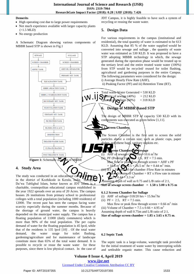
A Schematic Diagram showing various components of
MBBR based STP is shown in Fig.1
Figure 1: Schematic diagram of MBBR
4. Study Area
The study was conducted in an educational campus situated
in the district of Kozhikode in Kerala, India. „Jamiyyat
Da‟wa Tablighul Islam, better known as JDT Islam is a
charitable, cosmopolitan educational campus established in
the year 1922 spreads over an area of 20 Acres. The campus
houses 26 institutions from primary school to professional
colleges with a total population (including 1000 residents) of
12000. The recent past has seen the campus facing water
scarcity especially during the summer months. Because of
the shortage of ground water, the campus is heavily
depended on the municipal water supply. The campus has a
floating population of 11000 (daily commuters) which is
more than 90% of the total population. The per capita
demand of water for the floating population is 45 lpcd, while
that of the residents is 135 lpcd [10] . Of the total water
demand, the water usage for toilet flushing,
gardening/agriculture and for maintenance of landscape
constitute more than 65% of the total water demand. It is
possible to recycle or reuse the waste water for these
purposes, since there is low physical contact. In the case of
JDT Campus, it is highly feasible to have such a system of
recycling or reusing the waste water.
5. Design Data
For various requirements in the campus (institutional and
residential), the total quantity of water is estimated to be 613
KLD. Assuming that 85 % of the water supplied would be
converted into sewage and sullage , the quantity of waste
water was estimated as 530 KLD. It was proposed to have a
STP adopting MBBR technology in which, the sewage
generated during the operation phase would be treated up to
the tertiary level and the entire treated waste water (100%)
from STP would be recycled/ reused for toilet flushing,
agricultural and gardening purposes in the entire Campus.
The following parameters were considered for the design:
i) Average Hourly Flow Rate (AHF),
ii) Peaking Factor (PF) and iii) Retention Time (RT).
Total waste Water Generated = 530 KLD
Quantity of sewage (40%) = 212 KLD
Quantity of sullage (60%) = 318 KLD
6. Design of MBBR Based STP
The design of MBBR STP of capacity 530 KLD with its
components was executed as given below [1,11].
6.1 Screen Chamber
The Screen Chamber is the first unit to screen the solid
particles above a certain size; such as plastic cups, paper
dishes, polythene bags, sanitary napkins etc.
6.1.1 Screen Chamber for Sewage
(i) AHF of sewage=212/20hrs=10.6 m3/hr
(ii) PF (Peaking Factor) = 2.5, RT = 7.5 min.
Max flow or peak flow through screen = AHF x PF
= 10.6 m3 /hr x 2.5 = 26.5 m
3 /hr = 0.44 m
3 /min.
(iii) RT = Volume of the chamber /Flow Rate in minutes
Hence, Volume of Chamber = RT x Flow rate in minute
= 7.5 x 0.44 = 3.3 m3
Assuming depth of wall as 0.75 and L/B ratio of 2:1,
Size of sewage screen chamber = 1.50 x 3.00 x 0.75 m
6.1.2 Screen Chamber for Sullage
(i) AHF of sullage=318/20 hrs = 15.9m3/hr
(ii) PF = 2.5, RT = 7.5 min.
Max flow or peak flow through screen = 0.66 m3 /min
(iii) Volume of Chamber = 7.5 x 0.66 = 4.95 m3
Assuming depth of wall 0.75m and L/B ratio of 2:1,
Size of sullage screen chamber = 1.85 x 3.65 x 0.75 m.
6.2 Septic Tank
The septic tank is a large-volume, watertight tank provided
for the initial treatment of waste water by intercepting solids
and settleable organic matter. This cause reduction and
Paper ID: ART20197355 10.21275/ART20197355 1533
International Journal of Science and Research (IJSR) ISSN: 2319-7064
ResearchGate Impact Factor (2018): 0.28 | SJIF (2018): 7.426
Volume 8 Issue 4, April 2019
www.ijsr.net Licensed Under Creative Commons Attribution CC BY
decomposition of accumulated solids, provide storage for the
separated solids (sludge and scum) and allow the clarified
waste water to flow out of the chamber.
(i) AHF rate of Septic Tank = 212 /20 hr = 10.6 m3 / hr
(ii) RT of 1 day (Take 20 hrs.)
(iii) Volume of Septic Tank = 10.6 x 20 = 212 m3
Assume depth 3 m and L/B ratio of 3:4,
Size of Septic tank = 9.70 x 7.30 x 3.00 m
6.3 Oil Separator
The Oil Separator is used to separate solid and fatty matter at
source from the waste water before it is taken to the
equalization tank.
(i) AHF of OS = 318 / 20 hr = 15.9 m3 /hr
(ii) RT = 30 min., PF = 2.5,
Peak flow = 15.9 x 2.5 = 39.75 m3/hr = 0.66 m
3 /min.
(iii) Volume of OS= 30 x 0.66 = 19.875 m3
Assuming a depth of 1.25 m and L/B Ratio as 2 : 1,
Size of OS Tank = 5.65 x 2.85 x 1.25 m
6.4 Primary Settling Tank
After grit removal in grit chamber, the wastewater containing
mainly floating and settleable materials found in waste water
is settled in the primary settling tank (PST).
(i) Surface Loading for PST = 0.3 m3/ m
2 / hr
(ii) AHF for sullage = 15.9 m3 /hr
Area = AHF / Surface loading = 15.9/0.3 = 53 m2
(iii) Assuming a L/B Ratio of 2 : 1,
base dimension of the tank = 10.3 m x 5.2 m
Required depth of the tank is to be computed based on
the following conditions:
Tank to be designed with a cone at the bottom to
facilitate settling, with angle of inclination of the slope
between 300 - 60
0; max. height of cone as 2m;
height of rectangular portion at the top as 1m.
With trial and error method, it was found that two
tanks would be required instead of one.
With height of cone as 2m, and angle of inclination of
350, Size of one conical chamber was computed
as 5.5 x 5.5 x 2
Volume of conical chamber = 5.5 x 5.5 x 2/3
= 20.17m3
Volume of Rectangular portion = 5.5 x 5.5 x 1.0
= 30.25 m3
Total volume available = 2 (20.17+30.25) = 100.1 m3
Considering 4 hrs retention period,
Volume required = (530/ 20) x 4 = 106 m3
Volume available approx equal to volume required.
Dimension of PST = 11.00 x 5.50 x 3.00 m
6.5 Equalization Tank
The equalization tank is the first collection tank in an STP.
Its main function is to act as a buffer to collect raw sewage
that is coming at widely fluctuating rates, before it is passed
on to the rest of the STP at a steady flow rate.
(i) AHF = 530 / 20 hrs = 26.5 m3 / hr
(ii) RT of 12 hours,
(iii) Volume for ET = 26.5 x 12 hr = 318 m3
Assuming Square section and 3m height
Dimension for ET = 10.30 x 10.30 x 3.00 m.
6.6 Aeration tank
Aeration tank is the heart of aerobic treatment system. The
main function of the aeration tank is to maintain a high
population level of microbes. The mixed liquor is passed to
the clarifier tank, where the microbes are allowed to settle at
the bottom.
(i) Organic Loading rate = 1.2 kg/ m3 / day
Assuming a BOD of 350 mg/litre = 350 x 10-6
kg/litre
BOD in 530 KLD = 530 x 1000 x 350 x 10-6
= 185.5 kg/m3/day
(ii) Volume of AT = 185.5 / 1.2 = 155 m3
Assuming the Media Filling Factor = 0.5,
Media Volume = 155 x 0.5 = 77.5 m3
Required Number of Tanks = 2 Nos
(MBBR 1- Reaction Tank, MBBR 2- Stabilization Tank)
Assuming Square section and 3m height
Dimension of AT = 7.20 x 7.20 x 3.00 m
6.7 Secondary Settling Tank
The function of the secondary clarifier is threefold:
To allow settling of biomass solids in the Mixed Liquor
coming out of the aeration tank, to thicken the settled
biomass in order to produce a thick underflow and to
produce clear supernatant water in the overflow from the
clarifier. All the above actions occur due to gravity.
(i) Surface Loading Rate for SST = 0.5 m3 /m
2 /hr
(ii) AHF for total waste water = 530 / 20 = 26.5 m3 /hr
Area = AHF / Surface Loading = 26.5 / 0.5 = 53.5 m2
(iii) Assuming a L/B Ratio 2:1 and height = 3 m with 1m
rectangular portion at the top and 2 m, conical portion at
bottom with 350 inclination.
The design procedure is similar to the one presented in
Section 6.4
Dimension of SST = 11.00 x 5.50 x 3.00 m
6.8 Flocculation Tank
Flocculation refers to the process by which fine particulates
are caused to clump together into a floc. The floc may then
float to the top of the liquid (creaming), settle to the bottom
of the liquid (sedimentation), or be readily filtered from the
liquid.
(i) AHF = 26.5 m3 /hr = 0.44 m
3/min
(ii) RT = 5 Minutes
Length of Flocculation Tank = Width of Settling Tank
Length of Flocculation Tank = 5.2 m
Assuming the height of Flocculation tank to be 0.75 m
(iii) Volume of FT = 0.44 m3 /min x 5 min = 2.2 m
3
Dimension of FT =5.50 x 0.60 x 0.75 m
6.9 Tertiary Settling Tank
When the intended receiving water is highly vulnerable to
pollution, secondary effluent should be treated further by
tertiary process. The design procedure is similar to the one
presented in Section 6.7.
Dimension of TST = 11.00 x 5.50 x 3.00 m
Paper ID: ART20197355 10.21275/ART20197355 1534
International Journal of Science and Research (IJSR) ISSN: 2319-7064
ResearchGate Impact Factor (2018): 0.28 | SJIF (2018): 7.426
Volume 8 Issue 4, April 2019
www.ijsr.net Licensed Under Creative Commons Attribution CC BY
6.10 Chlorine Dosage
The filtered water from the tertiary settling tank should be
chlorinated before it is fed into the filter feed tank.
Assuming a chlorine dosage of 30 ppm,
Amount of chlorine required to disinfect 26500 litre/hr
= 26500 x 30 = 795000 mg /hr
Amount of chlorine solution required = 795000 mg /hr
= 795000/150000 = 5.3 litres/hr
Chlorine dosage per day = 5.3 x 20 = 106 litres/day
6.11 Filter Feed Tank
Filter Feed Tank is required to collect the water from the
tertiary settling tank before it is fed to PSF and ACF.
(i) AHF = 26.5 m3 /hr
(ii) RT = 8 hrs
(iii) Volume of filter feed tank = 26.5 x 8= 212 m3
Assuming a height of 3m and a square plan,
Dimension of FFT = 8.50 x 8.50 x 3.00 m
6.12 Pressure Sand Filter
The pressure sand filter (PSF) is used as a tertiary treatment
unit to trap the trace amounts of solids which escape the
clarifier, and can typically handle up to 50 mg/l of solids in
an economical manner. This is essentially a pressure vessel
filled with graded media (sand and gravel).
1) AHF = 530/20 = 26.5 m3 /hr
2) Specific flow rate of the filter = 12.50 m3/hr /m
2
3) Area = 26.5 m3/hr /(12.5 m
3/hr /m
2) = 2.12 m
2
Considering Circular dimension for the tank
Diameter of the tank = 1.6 m
Assuming total depth of PSF = 2.25
(Filter media depth of 1.5m + 0.75 m for expansion)
Dimension of PSF = 2.25 m Height with 1.6 m ɸ
6.13 Activated Carbon Filter
An activated carbon filter (ACF), like the pressure sand
filter, is a tertiary treatment unit. It receives the water from
the Pressure Sand Filter and improves multiple quality
parameters of the water like BOD, COD, clarity (turbidity),
color and odor. Ref 6.12
Dimension of ACF = 2.25 m Height with 1.6 m ɸ
6.14 Treated water Tank
Treated Water Tank is used to collect the treated water after
ultra filtration. The design procedure is similar to the one
presented in Section 6.11.
Dimension of TWT = 8.50 m x 8.50 m x 3.00 m
6.15 Ultra filtration
Ultra filtration (UF) is a pressure-driven barrier to suspended
solids, bacteria, viruses, endotoxins and other pathogens in
order to produce water with very high purity and low silt
density. Ultra filtration (UF) is a variety of membrane
filtration in which hydrostatic pressure forces a liquid against
a semi permeable membrane. Ultra filtration process is done
with respect to membrane specification. Based on the
efficiency of removal, low-pressure difference and lesser
area requirement, a membrane of PENTAIR of size 8”
diameter x 54 cm was selected as module.
Assuming the operating pressure of membrane as
2 kg/cm2 and back wash of 3 kg /cm
2,
AHF = 26.5 m3/hr
Taking the efficiency of module as 2m3/hr,
Number of Membrane Module required for filtration
= 26.5/2 = 13.35 = 14
Number of Membrane Module required = 14
6.16 Post Treated Water Tank / Roof Top Tank
Post Treated Water Tank (PTWT) is required to collect the
post-treated water. The volume of Post Treated water tank
and the Roof Top Tank (RTT) are same. The design
procedure is similar to the one presented in Section 6.11.
Dimension of PTWT & RTT = 8.50 m x 8.50 m x 3.00 m
6.17 Blower air Requirement
BOD loading = 185.5 kg / day
Oxygen Uptake Ratio = 1.25 kg of oxygen /kg of BOD
Oxygen required for 185.5 kg of BOD = 185.5 x 1.25
= 231.875 kg
Percentage of oxygen in air = 22.5 % = 0.225
Weight of oxygen required = 231.875 / 0.225 = 1030 kg
i.e., 1030 Kg of air is required to treat BOD of 185.5 kg
Density of air = 1.225 kg /m3
Volume of air = 1030 /1.225 = 840 m3 /day
Air transfuse efficiency of diffuser = 7.5 %= 0.075
Quantity of air required = 840 / 0.075 =11200 m3/day
Factor of safety 50% =11200m3/day x 1.5 =16800m
3/day
Volume of air required /hr = 16800/20 hr = 840 m3 /hr
Volume of Equalization Tank = 318.00 m3
Volume of Flocculation Tank = 2.20 m3
Total Volume = 320.20 m3
Air required for Equalization = 1.5 m3 / m
3 / hr
Volume of air required = 320 x 1.5 = 480 m3 /hr
Total Air required = Air required for BOD digestion + Air
required for Equalization= 840 + 480 = 1320 m3 /hr
Therefore,
Capacity of blower = 1320 m3 /hr
Paper ID: ART20197355 10.21275/ART20197355 1535
International Journal of Science and Research (IJSR) ISSN: 2319-7064
ResearchGate Impact Factor (2018): 0.28 | SJIF (2018): 7.426
Volume 8 Issue 4, April 2019
www.ijsr.net Licensed Under Creative Commons Attribution CC BY
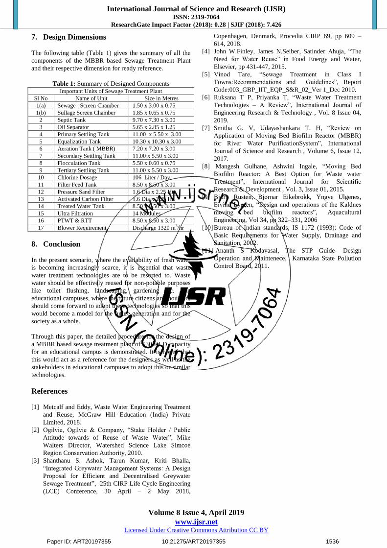
7. Design Dimensions
The following table (Table 1) gives the summary of all the
components of the MBBR based Sewage Treatment Plant
and their respective dimension for ready reference.
Table 1: Summary of Designed Components Important Units of Sewage Treatment Plant
Sl No Name of Unit Size in Metres
1(a) Sewage Screen Chamber 1.50 x 3.00 x 0.75
1(b) Sullage Screen Chamber 1.85 x 0.65 x 0.75
2 Septic Tank 9.70 x 7.30 x 3.00
3 Oil Separator 5.65 x 2.85 x 1.25
4 Primary Settling Tank 11.00 x 5.50 x 3.00
5 Equalization Tank 10.30 x 10.30 x 3.00
6 Aeration Tank ( MBBR) 7.20 x 7.20 x 3.00
7 Secondary Settling Tank 11.00 x 5.50 x 3.00
8 Flocculation Tank 5.50 x 0.60 x 0.75
9 Tertiary Settling Tank 11.00 x 5.50 x 3.00
10 Chlorine Dosage 106 Liter / Day
11 Filter Feed Tank 8.50 x 8.50 x 3.00
12 Pressure Sand Filter 1.6 Dia x 2.25 Ht.
13 Activated Carbon Filter 1.6 Dia x 2.25 Ht.
14 Treated Water Tank 8.50 x 8.50 x 3.00
15 Ultra Filtration 14 Modules
16 PTWT & RTT 8.50 x 8.50 x 3.00
17 Blower Requirement Discharge 1320 m3/hr
8. Conclusion
In the present scenario, where the availability of fresh water
is becoming increasingly scarce, it is essential that waste
water treatment technologies are to be resorted to. Waste
water should be effectively reused for non-potable purposes
like toilet flushing, landscaping, gardening etc. The
educational campuses, where the future citizens are moulded,
should come forward to adopt these technologies so that this
would become a model for the future generation and for the
society as a whole.
Through this paper, the detailed procedure for the design of
a MBBR based sewage treatment plant of 530 KLD capacity
for an educational campus is demonstrated. It is hoped that
this would act as a reference for the designers as well as the
stakeholders in educational campuses to adopt this or similar
technologies.
References
[1] Metcalf and Eddy, Waste Water Engineering Treatment
and Reuse, McGraw Hill Education (India) Private
Limited, 2018.
[2] Ogilvie, Ogilvie & Company, “Stake Holder / Public
Attitude towards of Reuse of Waste Water”, Mike
Walters Director, Watershed Science Lake Simcoe
Region Conservation Authority, 2010.
[3] Shanthanu S. Ashok, Tarun Kumar, Kriti Bhalla,
“Integrated Greywater Management Systems: A Design
Proposal for Efficient and Decentralised Greywater
Sewage Treatment”, 25th CIRP Life Cycle Engineering
(LCE) Conference, 30 April – 2 May 2018,
Copenhagen, Denmark, Procedia CIRP 69, pp 609 –
614, 2018.
[4] John W.Finley, James N.Seiber, Satinder Ahuja, “The
Need for Water Reuse” in Food Energy and Water,
Elsevier, pp 431-447, 2015.
[5] Vinod Tare, “Sewage Treatment in Class I
Towns:Recommendations and Guidelines”, Report
Code:003_GBP_IIT_EQP_S&R_02_Ver 1_Dec 2010.
[6] Ruksana T P, Priyanka T, “Waste Water Treatment
Technologies – A Review”, International Journal of
Engineering Research & Technology , Vol. 8 Issue 04,
2019.
[7] Smitha G. V, Udayashankara T. H, “Review on
Application of Moving Bed Biofilm Reactor (MBBR)
for River Water PurificationSystem”, International
Journal of Science and Research , Volume 6, Issue 12,
2017.
[8] Mangesh Gulhane, Ashwini Ingale, “Moving Bed
Biofilm Reactor: A Best Option for Waste water
Treatment”, International Journal for Scientific
Research & Development , Vol. 3, Issue 01, 2015.
[9] Bjorn Rusten, Bjørnar Eikebrokk, Yngve Ulgenes,
Eivind Lygren, “Design and operations of the Kaldnes
moving bed biofilm reactors”, Aquacultural
Engineering, Vol 34, pp 322–331, 2006
[10] Bureau of Indian standards, IS 1172 (1993): Code of
Basic Requirements for Water Supply, Drainage and
Sanitation, 2002.
[11] Ananth S Kodavasal, The STP Guide- Design
Operation and Maintenece, Karnataka State Pollution
Control Board, 2011.
Paper ID: ART20197355 10.21275/ART20197355 1536