Embed Size (px)
Citation preview

VOL. 12, NO. 17, SEPTEMBER 2017 ISSN 1819-6608
ARPN Journal of Engineering and Applied Sciences ©2006-2017 Asian Research Publishing Network (ARPN). All rights reserved.
www.arpnjournals.com
4996
DESIGN OF MARINE PROPELLER BLADE WITH DIFFERENT BLADE SEQUENCES ANALYSE THE HYDRO FORMATION
UNDER PRESSURE HYDRODYNAMIC FILL
K. P. Santhosh Babu and S. Padmanabhan School of Mechanical Engineering, Sathyabama University, Chennai, Tamil Nadu, India
E-Mail: [email protected]
ABSTRACT
Marine ducted propellers are rotating duct fan that are used on tugs and trawlers which creates a greater propulsive thrust force to drive over a water medium on heavy working condition in harbour. This paper progresses with comprehensive information of marine ducted propeller. Which blade made of aluminum alloy and duct of alloy steel is designed and analyzed with various blade formations 4 and 5 separately and to check the performances of each blade individually to show which blade performs efficiently better with maximum velocity rate under stream line motion on water at dynamic condition. Ducted propeller is modeled in solid works. Hydrostatic and hydrodynamic analyses of each blade are performed with ANSYS workbench. Keyword: marine ducted propeller, hydrostatic analysis, hydrodynamic analysis. 1. INTRODUCTION
Ducted propellers are rotating duct fan that transmits rotational motion into thrust force that helps the ships or tugs to move forward. Thus duct helps the tug to create a greater propulsion force at a lower rotational speed [13]. Ducts they are two types accelerating and decelerating ducts.
Accelerating ducted propellers are propellers that work on heavy loading condition. Thus this propeller helps in improving the propulsion of a ship at lower speed and reduces vibration over the tugs when at a unconditional flow rate of water.
Decelerating ducts produces lesser propulsive power than previous duct. This is specifically used for noise reduction purposes and for some harbour small loading and unloading purposes inside harbour [6].
Ducted propellers are applicable in tugboats and trawlers in which these boats work on harbor as helper boats which helps in towing of containers, wrecked or damaged ships, clearing of naval traffics etc. to tow a container ships of larger size tugs must perform with greater propulsive power and a lower RPM speed. This helps to create 30% of positive bollard pull [10]
When designing a propeller blade it’s always be a challenging role. That is we have to consider few factors which material to be chosen for blade and what type of propeller based on the application of marine field. When comes to designing part the propeller diameter, pitch, rake angle, and angle of attack are the main things to be considered initially.
Propellers are made of three materials when choosing material we have to look for good strength, durability, corrosion resistant and check for prices too. Three materials are composite plastics, aluminum alloy and steel alloy. Among three propeller material aluminum alloy are most common type with average durability light weight and strong enough to reduce blade flex and could also be repaired at very reasonable price. A well designed aluminum propeller with a duct will perform as efficiently
as the normal stain less steel propeller at various fluid terrains from normal to unconditional flow of water at the stream line velocity rate [7].
On comparison with the open propellers ducted propeller performs more laminar flow on a open water at a static condition, Thus the stream line flow velocity rate of the ducted propeller will be more then that of the open propeller, so the propulsion power increases, increase in propulsion power will also increases the performance of the propeller [1].
In this paper, a hydrostatic and hydrodynamic analysis of tug boat propeller is done with various blade formations. Tug boats performs with ducted propellers. Thus chosen blade material of aluminum alloy has a Good toughness and surface finish, excellent corrosion resistance, Good corrosion resistance to sea water, Good weldability and brazability, and for duct alloy steel is chosen [3]. And modeling of blade and duct is done. For tug boats and analyzed hydrostatic load separately for each blade formation to check which blade could withstand greater static pressure over it when water is at still position at rest and the ducted propeller blade is performed on it [9, 12]. Then hydrodynamic loading pressure is analyzed with the same procedure of analyzing separately for each blade arrangements [11]. But in this case blade on rotating forces creates a pressure and move over the dynamic water [2, 5]. Thus here dynamic loading is created. Due to both boat and water is in motion.
Based on comparison results of both hydrostatic and hydrodynamic analysis. It is to be concluded that which propeller performs efficiently at a greater propulsive performance. 2. PROPELLER DESIGN MODEL
Ducted propeller used for tug boats are designed in solid works. Figure-1 shows the ducted propeller being designed with various blade arrangements by choosing aluminum alloy for blade and alloy steel for duct.

VOL. 12, NO. 17, SEPTEMBER 2017 ISSN 1819-6608
ARPN Journal of Engineering and Applied Sciences ©2006-2017 Asian Research Publishing Network (ARPN). All rights reserved.
www.arpnjournals.com
4997
Figure-1. Ducted propeller design model. A. 5-Bladed existing propeller model
Solid works is used to design propeller blade model and here in Figure-2 it shows a propeller being designed with a 5-blade arrangement with aluminum alloy of 1060. To design a propeller pitch, diameter, rake angle and angle of contact are main design factors to be considered.
Figure-2. Propeller blade designed with 5-blade arrangement.
B. 4-Bladed new propeller model
Figure-3 it shows a propeller being designed with a 4-blade arrangement with aluminum alloy of 1060 having same pitch, diameter, and angle of contact.
Figure-3. Propeller blade designed with 4-blade arrangement.
3. PROPELLER MATERIAL USED
When choosing an material of a propeller it has to satisfy few key factors. It should be good corrosive resistance and less cavitations, good sustainable at various terrains with less vibration during a sail.
Figure-4. Aaluminum and alloy steel of ducted propeller. A. Aluminum alloy 1060
Application: Marine Components, Aircraft components etc.
Advantages: It has Good corrosion resistance, and workability. It has low mechanical strength compared to more significantly alloyed metals. It can be strengthened by cold working. B. Alloy steel
Application: Marine and jet engines Components, spacecraft and nuclear reactors components etc.
Advantages: It has good strength, it has low hardness. It has higher toughness, wear resistance and corrosion resistance it has good harden ability, and hot hardness. 4. PROPELLER MATERIAL PROPERTIES
DUCT BLADE
BUSH BEARING SLEEVE INSERT

VOL. 12, NO. 17, SEPTEMBER 2017 ISSN 1819-6608
ARPN Journal of Engineering and Applied Sciences ©2006-2017 Asian Research Publishing Network (ARPN). All rights reserved.
www.arpnjournals.com
4998
Table-1. Chemical composition of aluminum and steel alloy.
Chemical composition of material
S. No. Alloy steel 41xx S. No. Aluminum alloy 1060
1 Steel 99.38 1 Aluminum 99.60
2 Chromium 0.55 2 Copper 0.05
3 manganese 0.12 3 Iron 0.35
4 Magnesium 0.03
5 Manganese 0.23
6 Silicon 0.02
7 Titanium 0.03
8 Vanadium 0.05
9 Zinc 0.05
A. Aluminum alloy 1060
Table-2. The mechanical property of aluminum alloy 1060.
Material property 1
Material name Aluminum alloy 1060
Property Value Unit
Elastic modulus 6.90E^10 N/m^2
Poisson’s ratio 0.33 NA
Shear modulus 2.70E+10 N/m^2
Mass density 2700 Kg/m^3
Tensile strength 6.89E+07 N/m^2
Yield strength 2.78E+07 N/m^2 Thermal expansion
coefficient 2.40E-05 Kelvin
Thermal conductivity 200 W/(m.k)
Specific heat 900 J/(kg.k) B. Alloy steel 41xx
Table-3. Mechanical property of alloy steel 41xx.
Material property 2
Material name Alloy steel 41xx
Property Value Unit
Elastic modulus 2.10E+11 N/m^2
Poisson’s ratio 0.28 NA
Shear modulus 7.90E+10 N/m^2
Mass density 7700 Kg/m^3
Tensile strength 7.24E+08 N/m^2
Yield strength 6.20E+08 N/m^2 Thermal expansion
coefficient 1.30E-05 Kelvin
Thermal conductivity 50 W/(m.k)
Specific heat 460 J/(kg.k)
5. HYDROSTATIC ANALYSES Static analysis is performed to calculate pressure
by applying a certain load on a physical component either through pointed or equally distributed loads. Here in this case by keeping water medium at a rest position and performing propeller over it hydrostatic load is formed thus it creates stress, strain and deformation over the propeller blade due to concentric pressure created over the propeller. Figure-7 shows the boundary condition of tug boat under hydrostatic pressure.
Figure-5. Boundary layer of tug under hydrostatic pressure.

VOL. 12, NO. 17, SEPTEMBER 2017 ISSN 1819-6608
ARPN Journal of Engineering and Applied Sciences ©2006-2017 Asian Research Publishing Network (ARPN). All rights reserved.
www.arpnjournals.com
4999
Figure-6. Hydrostatic pressure on tugboat.
Figure 7-12 shows the static analysis of a ducted propeller blade with 4 and 5 blade formations each to calculate stress, strain and displacement individually. A. Static analysis on 5-blade propeller
Figure-7. Stress analysis of a 5-blade arrangement propeller on hydrostatic loading.
Figure-8. Strain analysis of a 5-blade arrangement propeller on hydrostatic loading.
Figure-9. Displacement of a 5-blade arrangement propeller on hydrostatic loading.
B. Static analysis on 4-blade propeller
Figure-10. Stress analysis of a 4-blade arrangement propeller on hydrostatic loading.
Figure-11. Strain analysis of a 4-blade arrangement propeller on hydrostatic loading.

VOL. 12, NO. 17, SEPTEMBER 2017 ISSN 1819-6608
ARPN Journal of Engineering and Applied Sciences ©2006-2017 Asian Research Publishing Network (ARPN). All rights reserved.
www.arpnjournals.com
5000
Figure-12. Displacement of a 4-blade arrangement propeller on hydrostatic loading.
6. HYDRODYNAMIC ANALYSIS
Dynamic analysis is performed when both the medium are in motion during such process a dynamic pressure is created over the physical component calculating the pressure is said to be hydrodynamic pressure. Here in this case the propeller with four different arrangements are is analyzed in CFX software individually to check the performances of propeller. Figure-13 shows the dynamic performance of a propeller
Figure-13. Dynamic analysis of propeller.
Table-4. Shows the boundary layer condition of dynamic analysis.
S. No. Boundary parameter Value
1 Water angular velocity 35 rad/sec
2 Inlet velocity 50 m/s
3 Pressure range 0~1pascal
4 Blade angular velocity 35 rad/sec
5 Stream line points 150 points
Figures 14 and 16 shows the stream line motion
velocity rate of propeller when water medium in dynamic condition for all four arrangements of blade formations individually. To check the performance of the propeller
A. 5-bladed propeller dynamic analysis
Figure-14. Dynamic analysis of 2-blade propeller.
Figure-15. 5-blade water flow condition during stream line motion.
B. 4-bladed propeller dynamic analysis
VOL. 12, NO. 17, SEPTEMBER 2017 ISSN 1819-6608
ARPN Journal of Engineering and Applied Sciences ©2006-2017 Asian Research Publishing Network (ARPN). All rights reserved.
www.arpnjournals.com
5001
Figure-16. Dynamic analysis of 2-blade propeller.
Figure-17. 4-blade water flow condition during stream line motion.
7. RESULT AND DISCUSSIONS
From the dynamic analysis the best performed propeller with better stream line motion velocity is derived.
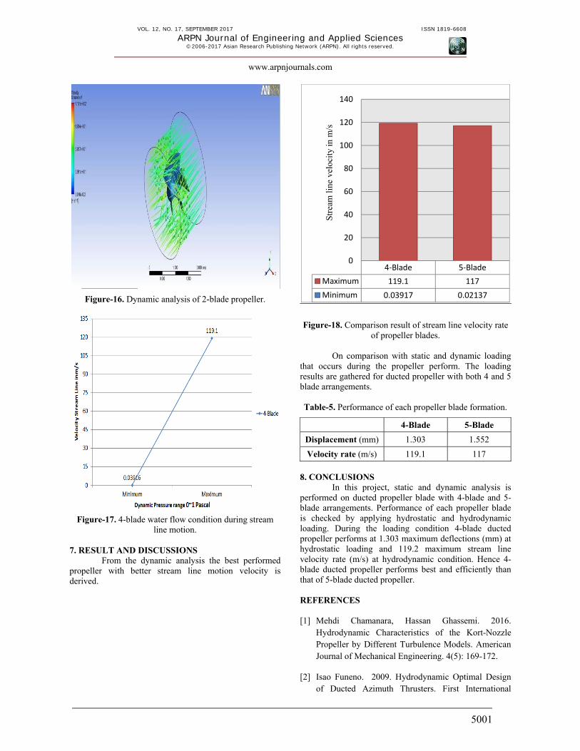
Figure-18. Comparison result of stream line velocity rate
of propeller blades.
On comparison with static and dynamic loading that occurs during the propeller perform. The loading results are gathered for ducted propeller with both 4 and 5 blade arrangements. Table-5. Performance of each propeller blade formation.
4-Blade 5-Blade
Displacement (mm) 1.303 1.552
Velocity rate (m/s) 119.1 117
8. CONCLUSIONS
In this project, static and dynamic analysis is performed on ducted propeller blade with 4-blade and 5-blade arrangements. Performance of each propeller blade is checked by applying hydrostatic and hydrodynamic loading. During the loading condition 4-blade ducted propeller performs at 1.303 maximum deflections (mm) at hydrostatic loading and 119.2 maximum stream line velocity rate (m/s) at hydrodynamic condition. Hence 4-blade ducted propeller performs best and efficiently than that of 5-blade ducted propeller. REFERENCES [1] Mehdi Chamanara, Hassan Ghassemi. 2016.
Hydrodynamic Characteristics of the Kort-Nozzle Propeller by Different Turbulence Models. American Journal of Mechanical Engineering. 4(5): 169-172.
[2] Isao Funeno. 2009. Hydrodynamic Optimal Design of Ducted Azimuth Thrusters. First International
4‐Blade 5‐Blade
Maximum 119.1 117
Minimum 0.03917 0.02137
0
20
40
60
80
100
120
140
Stre
am li
ne v
eloc
ity in
m/s

VOL. 12, NO. 17, SEPTEMBER 2017 ISSN 1819-6608
ARPN Journal of Engineering and Applied Sciences ©2006-2017 Asian Research Publishing Network (ARPN). All rights reserved.
www.arpnjournals.com
5002
Symposium on Marine Propulsors smp’09, Trondheim, Norway.
[3] Jaruphant Noosomton, Jarruwat Charoensuk. 2015. The New Propeller Design 3 Blades Type on 18o Skew Angle and Testing Cavitation of Tailing Thai Boat. International Journal of Engineering Research. 4(5): 257-263.
[4] Stefano Gaggero, Cesare M. Rizzo, Giorgio Tani, Michele Viviani. 2012. EFD and CFD Design and Analysis of a Propeller in Decelerating Duct. International Journal of Rotating Machinery, Article ID 823831, Volume 2012.
[5] Xueming He1*, Hecai Zhao2, Xuedong Chen2, Zailei Luo2, Yannan Miao2. 2015. Hydrodynamic Performance Analysis of the Ducted Propeller Based on the Combination of Multi-Block Hybrid Mesh and Reynolds Stress Model, Journal of Flow Control, Measurement & Visualization. 3, 67-74.
[6] J.Baltazar1, J.A.C. Falcão de Campos1 and J. Bosschers2. 2011. Open-Water Thrust and Torque Predictions of a Ducted Propeller System with a Panel Method, Second International Symposium on Marine Propulsors smp’11, Hamburg, Germany.
[7] Hongyang Fan1, Ye Tian2, Spyros A. Kinnas3. 2015. A Panel Method for Prediction of Performance of Ducted Propeller, Fourth International Symposium on Marine Propulsors smp’15, Austin, Texas, USA.
[8] Krzysztof szafran, oleksandr shcherbonos, dariusz ejmocki*. 2014. Effects of Duct shape on ducted propeller thrust performance, transactions of the institute of aviation, ISSN 2300-5408, No. 4 (237): 84-91, Warsaw.
[9] A.SánchezCaja1, J.V.Pylkkänen2, Tuomas P.Sipilä1. 2008. Simulation of the Incompressible Viscous Flow around Ducted Propellers with Rudders Using a RANSE Solver, 27th Symposium on Naval Hydrodynamics Seoul, Korea, 510.
[10] Anirban Bhattacharyya1, Jan Clemens Neitzel2, SverreSteen1, Moustafa Abdel-Maksoud2, Vladimir Krasilnikov3. 2015. Influence of Flow Transition on Open and Ducted Propeller Characteristics, Fourth International Symposium on Marine Propulsors smp’15, Austin, Texas, USA.
[11] Rodolfo Bontempoa, Massimo Cardonea, Marcello Mannaa, Giovanni Vorraroa. 2013. Ducted propeller
flow analysis by means of a generalized actuator disk model, Energy Procedia 45 (2014) 1107 - 1115 1876-6102 © 2013. Published by Elsevier Ltd, Science Direct 68th Conference of the Italian Thermal Machines Engineering Association, ATI.
[12] Zhi-Qiang Rao, Wei Li, Chen-Jun Yang. 2013. Simulation of Unsteady Interaction Forces on a Ducted Propeller with Pre-swirl Stators. Third International Symposium on Marine Propulsors smp’13, Launceston, Tasmania, Australia.
[13] Zoran Radisic, Principal Types and Characteristics of Harbour Tugs. 2003. Visoka pomorska skola zrinsko-frankopanska 38, 21000 split, republika hrvatska ntegrated transport review u. d. c.: 656.618, September 30.