Embed Size (px)
Citation preview

Design of Machine Elements IProf. G. Chakraborty
Department of Mechanical EngineeringIndian Institute of Technology – Kharagpur
Lecture – 20Shaft Coupling - I
Dear student, you are now going to begin lectures on machine design part 1. This is lecture
number 20 and the topic is shaft coupling. So, this is first of lectures on the same topic. Now,
couplings are normally used to connect 2 shafts axially. Now, the shafts are usually manufactured
in small pieces in order to avoid the difficulties or disadvantages of transport problem. And
whenever they are connected they are connected by means of this coupling.
Now, there are another device which serves the same purpose this is known as the clutch. The
important difference between the clutch and the coupling is that the clutches are used in order to
disengage and engage the shafts frequently. Whereas couplings are used to fasten them together
and this is permanent connections and they are only opened up during replacement or repair or
maintenance.
So, this is one of the important differences of coupling. Now, the couplings are used mainly to
transmit power without any loss.
(Refer Slide Time: 02:04)

This is what we want to say that transmit power without any loss that is very much expected and
second provide for shaft misalignments. Now, shafts are normally installed without any
misalignment but because of various reasons there will be inevitable presence of misalignments.
Now, the misalignment may be of different types. Let us see suppose we want this shaft to be
connected this way. So, this is the ideal situation 2 shafts axially connected.
This fashion and there is no misalignment. There may be misalignment for example one shaft is
here so this one is ideal there may be misalignment when one shaft is here and the other shaft the
axis of that shaft is offset by certain distance delta this is one kind of misalignment. There may
be another kind of misalignment that is there is one shaft then other shaft is (()) (03:38) a little bit
by an angle alpha this is one such misalignment.
There may be a combination of this 2 that is a shaft may be there and the other shaft is both
angularly misaligned that is angle alpha between these 2 axis and there is offset delta. So, there
are 4 kinds of misalignments and those are to be avoided. But normally this misalignment occurs
in practice and it is difficult to avoid. Then we have provisions that is coupling had to use in
order to provide for end movement of the shaft.
(Refer Slide Time: 04:31)
Now, the types of shaft coupling there are 2 types, 2 principal types of shaft coupling one is rigid
coupling and another is flexible coupling. As the name suggest rigid coupling are couplings

without any flexible member there are different kinds of rigid couplings. We have to discuss 4
which are the principle types of rigid coupling namely the first one is flange coupling. This is the
most commonly used coupling. The second one is sleeve or muff coupling.
Third one clamp coupling or sometimes it is called sleeve, muff coupling then compression
coupling. Flexible couplings are of 2 types one is coupling with kinematic flexibility that is we
insert certain members which undergoes rigid body translation of rotation but that gives a little
bit resilience or flexibility in the overall joint. The second type is coupling with resilient
members now here we introduce some members which have the flexibility.
So this is in (()) (05:39) flexible couplings. We are going to discuss in this lecture the principle
types of rigid coupling.
(Refer Slide Time: 05:47)
Now, let us come to few types of flange coupling. Now, flange couplings you see these are
coupling again rigid couplings and the couplings is done by means of 2 flanges. What you see
here is the cross section of such a flange coupling here the shaft and on top of it this part which is
known as the flange. It has 2 sections one is here which is relatively thick part it is known as hub
and this part which is relatively narrow then this is known as the flange.

And this 2 flanges are connected by means of few bolts. Now, bolts are arranged angularly
equispaced on particular circle. This is known as ball circle here you see the diameter of the ball
circle is T1. The diameter of the shaft is small d and the outer diameter of this flange is d2 and I
am sorry outer diameter is d and the hub diameter is d2. So, this is a protected type flange
coupling.
Sometimes we do not have this part and this is called unprotected type of flange coupling. Now,
why these protections because you know the shafts they rotate this is the definite purpose of the
shaft whenever they rotate then we need some safety. Suppose, something goes wrong this bolt
fails then it may come out and because of the large rotational speed a havoc can occur and so it
may be catastrophic.
In order to prevent this catastrophic that is for the work safety purpose we give this (()) (07:49)
extensions which is called the protections. Now, this is known as the protected type flange
coupling then in some applications for example in boat propeller shafts for the torque
transmission is relatively large there the flanges are integrally coupled. They are manufactured
along with the shaf.t
So this flange and shaft they come as one piece and they are connected by means of this bolts
now here you see there is no nut. This bolt is a special kind of bolt is a taper bolt and they make
the secure connections you will also see there are 2 protrusion here so one side of the flange
there is a little protrusion and on the other side there is recess made. What is the purpose of that?
So, these are called resistors and the purpose is to align this 2 shafts.
Sometime other kinds of alignments are also done. For example, by keeping some rings over
here on the on the surface of the flange. So, these are few kinds of flange coupling.
(Refer Slide Time: 09:07)

The usual design parameters of flange couplings are given here. D1 as I said which is = the bolt
circle diameter. This is roughly taken to be twice d this is the diameter of the shaft +50 in
millimeter that is 50 millimeter or it may be 3 d. Now, why all this? Because the couplings are
now manufactured by different manufacturer and so we have to come to a standard. These are
normally the standard followed unless otherwise specified to the manufactures.
There are catalogs available from the manufacturers and we are have to look up into this catalogs
to find out exact diameter. But what you see here are normally the usual dimensions maintained
in practice. D2 which is the hub diameter is 1.5 times d + 25 millimeter or it may be twice of
diameter of shaft. Everything is mentioned in terms of the diameter of the shaft. The outer
diameter is 2.5 times d + 75 millimeter or roughly 4 d length which is quite important.
It is about 1.25 times d +18.75 millimeter you see this odd figure but these standards. tf the width
of the or the thickness of the flange which I have just told in the last slide is .5d and n that is the
number of bolts that may be 3, for d up to 40 millimeter. 4, for d up to 100 millimeter. 6, for d up
to 180 millimeter. So, these are the usual dimensions which are maintained in practice.
(Refer Slide Time: 11:05)

Now, let us come to the design criteria of flange coupling. So, these are the 2 flanges which are
connected by bolts. Obviously, the most important part will be the bolts there are 2 possibilities
first one is that there is no clearance between bolt and hole. And there may be no clearance. So,
depending upon that the situation will change whenever we have clearance then we see the
failure will be different then the case where there is no clearance.
Let us see one-by-one. Whenever there is clearance then the bolts, there are bolts here different
bolts on the circle, bolt circle and the main pressure that is the flanges are connected because of
the friction force developed by the normal force and this normal force is given by the bolt. Let us
say there are n such bolts and each bolt is given a tension F. So, the total force on each flange
will be nF.
Now assume that the force is uniformly distributed that pressure is uniformly distributed so
therefore using the uniform pressure theory the overall torque capacity will be = nF times mu
times this distance that is the equivalent distance which is =, let us say d equivalent and as we
have derived in the lecture on power screw, d equivalent is twice third Ro cube –R inner cube
divided by Ro square –R inside square. So, this is the torque transmission.
Now, this torque transmission will be the same as the transmission on the shaft and if you use
this formula then you get F. Now, F is related to let us say Ab the bolt cross section now this will

be the minimum cross section that near the root of the thread times sigma tension allowable.
Now, this is = again sigma ten allowable will be = Sy/some factor of safety. Now, know all this
we can find out the Ab.
Now, there is another way of failure that is by the clashing of the bolt. How does it occur? Let us
see. So, if the forces are on each of the bolt the force is let us say small f then the total crossing
area will be this projected area. There is n such projected areas and this will be = n times d of
bolts that is the bolt diameter times the length of the tf, the flange thickness. So, this is total force
and this will be the area.
So therefore the total (()) (16:10) stress will be n times dp times tf and that must be <= sigma
bearing stress and sigma bearing stress will be = about twice that of S of that is Sc is the ill stress
in compressions divided by factor of safety and roughly twice of that and so this is the f and now
f is again if you assume the entire force is distributed here it will be T divided by this radius of
the bolt circle that is D1/2.
So, using this formula we can calculate the db that is the bolt diameter. Now, this is how the bolt
diameters are selected. Now, what happens when there is no clearance then of course the failure
mode will be the shared across the surface. So, now the sharing force the total sharing force will
be tau. This is the maximum shared stress this is tau max times the total sharing area. It will be =
times n times this area ab.
This is the total shared force and that is when multiplied by D1/2 should give T the torque
transmitted and there from we may calculate ab. Now, the tau allowable that is tau max will be =
is normally taken to be .6 times Sy/Sf that is .6 times the allowable tensile stress which is = ill
stress divided by factor of safety roughly taken to be 2 to 3. This is how the bolts are designed
then what are other important things?
The other important things will be this hub diameter which was named D2. Now, how this is
calculated? This is calculated based on the principle of shared stress due to torsion. Here you see

if you consider this hub to be a hollow cylinder then the total shared stress will be = the torque
transmitted times the maximum shared stress here on this surface =D2/2 divided by pi/32.
(Refer Slide Time: 19:32)
Now outside dimeter to the power 4 that is D2/4 - d/4 and this must be <= tau allowable. So, this
is how we may design the D2. Now, sometimes we have to check for the design that is the design
data already there we have to check. Now, we have to use this formula in order to check the
safety of the design. Another thing is this tf. Let us see how to calculate that. Now, the tf when
you take this part of this flange then so this is tf.
(Refer Slide Time: 20:46)
Now the total force on this side will be = let us say we assume that the total force is F now that
divide by the area will be the shared stress the total area is pi times let us say here. So, pi times
D2, always say D2 is here pi times D2 times tf this is the shared stress and that must be less then
tau allowable. And again F is related to the torsion by this formula that is D2/2. So, if you use
these 2 formulas then you can find out the safe value of tf.
Now, this is how the flanges are designed.
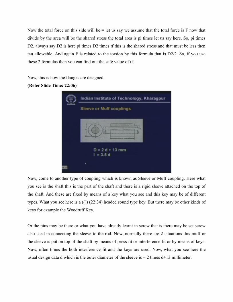
(Refer Slide Time: 22:06)
Now, come to another type of coupling which is known as Sleeve or Muff coupling. Here what
you see is the shaft this is the part of the shaft and there is a rigid sleeve attached on the top of
the shaft. And these are fixed by means of a key what you see and this key may be of different
types. What you see here is a (()) (22:34) headed sound type key. But there may be other kinds of
keys for example the Woodruff Key.
Or the pins may be there or what you have already learnt in screw that is there may be set screw
also used in connecting the sleeve to the rod. Now, normally there are 2 situations this muff or
the sleeve is put on top of the shaft by means of press fit or interference fit or by means of keys.
Now, often times the both interference fit and the keys are used. Now, what you see here the
usual design data d which is the outer diameter of the sleeve is = 2 times d+13 millimeter.

Again this is taken from the standard and L is normally taken to be 3.5 times the diameter. Now,
what will be important design criteria here? Of course, the first design criteria will be that the
stresses in the key if the key is the main load bearing member sometimes keys are not main load
bearing member but the torque is transmitted by the friction force generated on the surface. Here
the friction force is generated because of the interference fit.
Then there may be the stresses in the sleeve itself. So, there are few design criteria which we
have to see.
(Refer Slide Time: 24:27)
Now, let us look at the design criteria of sleeve coupling. The first one let us consider that the
sleeve is put over the shaft by interference fit and then what happens? Then of course the stress
will be developed in the sleeve. Now, this is the outer diameter D and this is the inner diameter
this is that of sleeve and this is the inner diameter that is that of the shaft. And this d now this is
the sleeve.
Now whenever there is interference fit or shrink fit then there will be the pressure develop. Then
because of this internal pressure there will be the stress is developed and the stresses may be
calculated by means of Lame’s equations which is sigma r that is there will be both radial stress
and circumferential stress. So, if you draw sigma r and there will be sigma theta. So, there will be
both radial stress and circumferential stress.

And those are given by this formula that is C2/r square and sigma theta is C1+C2 divided by r
square. So, they vary in inverse proportional of r square. Now, when we use the boundary
conditions suppose it is subjected to pressure in the inner surface so the boundary conditions will
be definitely sigma r will be = -p if p is the pressure at ri=d/2 and sigma theta, the boundary
conditions will now be in terms of sigma theta.
But everytime in terms of sigma r. sigma r will be zero at r =D/2 that is there is no pressure
applied at the outside surface whereas there is the pressure p which introduce a compressive
stress at the inner periphery. When you use this then you get the value of C1 and C2 in terms of
p. Now, whenever there is interference fit the problem is little complicated there what you get is
you cannot get p, directly but you will have to use the kinematic relationship.
So, in case of interference fit we have to use the kinematic relationship that is suppose the initial
difference between the shaft and the sleeve the diametric difference let us say delta.
(Refer Slide Time: 28:06)
So, after the shrink fit the radial deflections will be delta/2 and this will be = u2 that is if we
consider this is material 2 and that is material 1 then u2 will be the deflections the radial
deflections of this point -u1. So, this difference will be delta/2 and again you know epsilon theta

will be = u/r this is known for axis symmetric problem and of course we know that this will be =
1/E sigma theta –nu sigma r. So, this is the generalized Hooke's law.
When you use all these equations then you get the following thing.
(Refer Slide Time: 29:32)
That is the pressure will be = delta E/2 internal radius times 1-d/D square. So, from this we get
the value of p. Now once this p is calculated by this knowing this value we can calculate p. Of
course here we have assumed that these materials are the same that is they have the Young's
modulus and Poisson's ratio. Then this p once known then we can calculate the torque
transmitted the total force on the circumference will be = p times mu.
And the area that is = pi times d times L the length of the sleeve this is the total force times d/2
and that will be = the torque. So, this is the torque capacity of such a coupling. Of course from
here we can find out various things that is we can find out the busting pressure inside sigma theta
and sigma r etcetera knowing this p. I am doing this Lame’s equations and this sigma r and sigma
theta must be less than some limiting value or allowable value.
Now let us come to the situation where the keys are the main load bearing member.
(Refer Slide Time: 31:38)

So what I am drawing here half portion of such a sleeve. So, this is half of the sleeve here this is
the key is the main load bearing member now you have to calculate the design that is the width
and height of the key but this I leave that to you. Because now you know, how to design such a
key. Once the key is designed then we have to check for the pressure or the stress inside the
sleeve.
What you see is that there the stresses will be developed here we have the pressure which is
transmitted from the shaft through key to the sleeve and that causes a tensile stress over here. So
whenever such a situation occurs then there is a possibility that it may break from this point.
Now, we have to calculate the tensile stress? What will be the total force? The force let us say we
calculate the total force will be = F.
And if it is uniformly distributed if we assume that this force is uniformly distributed then the
equivalent point of application of this load is here which is let us say this distance if this height is
2h then half of the height is there. So, this distance will be = d/2 +h/2 and that will be = torque.
Now this is how we calculate F and the stress over this section will be then sigma=F divided by
this area and that will be = the length of the sleeve times this length.
Which = x and that must be less then = sigma allowable. How to calculate x? That comes from
plain geometry, what you see here. Suppose the width is w then you can find out if this diameter

is let us say D then what you have x= D/2 square-W/2 square-h-d/2 square-w/2 square. So, this is
how we calculate x that is plain and simple if you consider 2 right angle triangles here and then
this equation comes automatically.
After having calculated this value we can check for the stress sigma and that must be less then
this allowable stress. So, this is how we have to check. The other stress of course which is very
important will be that of the shear stress.
(Refer Slide Time: 35:23)
And again here the shear stress if you consider the torque then the torque distribution will be =
here the maximum torque is T and that occurs in that section and in that case the shear stress will
be T times the maximum shear stress will be D/2 divided by pi/32 D square-d square and that
must be less then = tau allowed. So, this is how we calculate the stresses in a sleeve coupling.
Now we come to another type of coupling known as the clamp coupling.
(Refer Slide Time: 36:40)

This is sometimes called the split muff coupling also. Here instead of using one single piece of
sleeve we use a split sleeve that is it is made of 2 parts and they are now connected by means of
few bolts. As you see here, this is made of 2 parts and they are connected by few bolts then there
are (()) (37:10) arrangement in order to give additional strength. Now, here the design parameters
which you see here.
This will be same all most the same as that of the sleeve bearing, sleeve coupling and the length
is also the same. But what would be the important design parameter here. The design parameter
will be definitely the failure of the bolt. Here the bolts may fail. So, we have to consider the
failure of the bolts which we do now. Now, let us consider the part of the sleeve and we have bolt
here.
(Refer Slide Time: 38:04)

Now, let us assume that each bolt is given a clamping force F. So, if there are n such bolt then the
total clamping force will be nF and this is supported or balanced by pressure developed. So, the
pressure will be = the projected area times the uniform pressure. So, projected area will be d
times L the length of the sleeve times p. So, this is how we calculate p. Now if you assume
uniform pressure then of course the friction force will be = mu times the pressure and that will
also uniform.
So, the total frictional force will be = mu times p times the area that will be = pi/2 times d times
L. So, this is the total force times d/2 will be = torque. Now this is from one side so you have to
use factor 2 because there is another half sleeve appearing here this side. So, therefore you have
to multiply it by 2 but in order to have a safe design we neglect this 2 because we assume that
half of the bolt carry the load and that is a safe design.
So from this when you substitute p here then you get F in terms of T and other things d etcetera,
etcetera. So, you get everything in terms of T and if is a A bolt times the sigma allowable. This is
the allowable force the maximum force available from this we calculate the bolt diameter
looking up at the table. So, this is one such example of the torque transmitted by the friction as
you see here.

Then of course the other forces or other stresses in the members will be same as that of sleeve
bearing which we are not going to say right here. We now come to the next type of coupling
which is known as the compression coupling.
(Refer Slide Time: 41:30)
Here the methodology is that we use the principle that whenever we insert wedge then it
develops a large frictional force. So, that advantage of wedge is taken help of here. What you see
here this is the cone type sleeve you see the cone and this is the shaft and this will be a double
cone type these are again split types of cones but they are wedge so they have a wedge actions
and the axial force to this wedge.
So, they have a wedge actions and the axial force to this wedge is given by tightening the bolts.
The bolts are made spare cross sections in order to have a larger tightening force on the nut. The
usual dimensions are written here this radius that is the inner most radius of the cone will equal
to about 1.5 times deep whereas the outer most radius of this wedge is about 1.875 times deep
and the final that is the outermost radius is 2.585 times deep.
So, this is one such coupling which is known as Seller’s cone coupling. Then we have another
kind of coupling this is known as flange type or ring type coupling. What you see here is a flange
type coupling you see here we have a continuous sleeve but this is not straight but this is made a

little conical and there are flanges put on top of this sleeve but this too have again the conical
surface and again these 2 flanges are tightened by means of bolts.
The bolt design will be same as that of the flange coupling but here you will have to consider the
force transmitted because of the wedging actions here as you can always guess. So, this you have
studied in your mechanic’s class I am not going to derive it here. Another way of applying the
coupling is to have such kind of couple the cone type muff or sleeve and then 2 rings are put
again by interference (()) (44:18) we developed a large pressure here.
And that usually transfers the torque from one shaft to the other shaft. Now, this is quite
advantageous when you use in the outdoor conditions where there may be environmental
hazards. It may be rusted the whole coupling so it will be very difficult to disassemble them if
you use such kind of coupling then it is quite easy to disassemble the entire shaft and the
coupling.
So, these are one of the advantages of the compression coupling, ring type compression
coupling.
(Refer Slide Time: 45:07)
Now, we come to one of the very important factors here that is the service factors for typical
machines. What is meant by serve factor? Now, everytime I design with a constant torque and
how to rate this torque? This torque may be rated from the diameter of the shaft. So, this is the
maximum torque which could be transferred but it seldom happens that the torque is constant
because the shafts are used to drive various machines.
So, there will be define some fluctuations of the torque. So the total torque will be = T fixed
torque that is the static torque + T dynamic torque. So, this T dynamic torque varies from
machine to machine and we have to take this as a factor here on the static torque. So, whenever
we have a static torque that this is fairly known then we have to multiply by this factor and how
to derive this factor again these are derived only from the previous experience.
So this is known as the service factor. Let us see the typical service factors. Now machines with
small accelerated masses here you see the service factor 1 to 1.5. Then the medium masses and
variable load that happens in for example in piston compressors, in planners, in grinding mills
and the service factor is taken to be 1.5 to 2. Then heavy masses and shock loads. Here the
service factor is 2.5 to 3 the usual machines.
Where this heavy masses and shock load occur, some examples are power hammers, rolling
mills, and ball mills. So, there are various other machines also available and these are fairly
tabulated and coupler of manufactures they provide all this data. So, whenever you have to select
the coupler then you have to look for the typical service factor. If the machinery is now powered
by IC engine then k is increased by 20% to 40% now that is very important.
Because IC engines all of you know that the force or the torque transmitted by IC engine is very
irregular. For example, in a 4 stroke engine we have in 1 stroke there is large compressions so
there is a large power stroke here the force is very large and in another stroke there is a small
force also but in 2 other strokes there are practically no force. So, therefor whenever we have IC
engines then the fluctuations in the torque is very, very large.
Therefor in case of IC engines we have to increase k by a factor of 20% to 40%. Now, the larger
value being for small number of cylinders whenever we have multiple cylinders IC engines then
that fluctuations could be little bit reduced and that is the advantage of multi-cylinder engine.

Whenever we have multi-cylinder engine then the power strokes happen in one cycle in 4 stroke
there is 1 power stroke.
But now for n cylinders there will be n such power strokes so the distribution is little bit even.
So, whenever we have larger value then that happens for small number of cylinders.
(Refer Slide Time: 49:10)
Now, let us see some of the disadvantages of the rigid couplings. Now, the first disadvantage as
you see is no provision for shaft misalignment. Since was rigid then if this is the coupling then
here suppose we have a shaft and this is coupled here. Another shaft suppose initially here then
when we connect it gets bend as you see very well that gets bend. And therefor whenever such
cases occur then there is a huge bending stress developed.
So, there is a huge bending whenever the shaft is misaligned hence rigid coupling is not suitable
whenever there is large misalignment. The second is that the large bending stress here you see
take for example a beam which is supported on to such simple supports then of course there is no
bending stress here that is from the conditions kinematic relationship of such kind of support.
But a rigid coupling is taken to be a fixed clamp.
So therefore whenever we have rigid coupling then there will be a large bending stress
developed. If you compare this with a cantilever beam which has again fixed end, then you see

the bending stress will be maximum here. So, large bending stress is developed. The third point
is that shock and impact loads gets transmitted that is very important because sometimes shock
appears in one machine for example which is connected to one part of the shaft.
It should not be transferred to the other shaft. So coupling should have adequate flexibility in
order to restrain this impact but a rigid coupling cannot restrain this impact. Let us see if you
have one mass and a flexible object which has flexibility that is stiffness k. If you have this force
fo cosine omega t that is a variable force with a frequency omega, then you see the total force
transmitted on the other side that is on the base will be k times the displacement.
K times the displacement and that will be = Fo if you calculate you Fo divide by 1-omega/omega
natural square. Omega natural is the natural frequency as omega natural square is K/m so
whenever we increase this omega then we see the entire force whenever we see omega n we
increase omega n then this becomes very, very small so the entire force gets transmitted to this
side.
Whereas if we have small value of omega n then of course the total force transmitted will be
very, very small. So this is one of the advantage of a flexible member that is if we have a large
variable force here then the transmitted force will be relatively small if the flexibility is property
chosen but we have to avoid one condition that omega should not be near = the omega n where
the force transmitted is very much increased.
So, these are the disadvantages and this above disadvantages can be reduced to some extent by
flexible couplings. So, there are few kinds of flexible couplings but we are not going to discuss
today. We postpone it until the next lecture. So, for time this being I take leave.
(Refer Slide Time: 54:15)

Dear student, let us begin the lecture on Machine design part 1.
(Refer Slide Time: 54:28)
This is lecture number 21 and the topic is shaft couplings. This is the concluding lecture on the
same topic. So, before going to the subject for today let us recapitulate little bit what we have
learnt in last lecture. We talked about the couplings. Now couplings are used to connect 2 shafts
for relatively long time and there are primarily 2 types of couplings one is rigid coupling as the
name suggest the coupling is made of rigid material.

There are few kinds of rigid couplings which we discussed namely flange coupling which is the
common type of coupling. Then sleeve or muff coupling then we discussed clamp coupling and
then compression coupling. But towards the end of the lecture we mentioned that there are few
disadvantages of the rigid coupling. So, we are going to start from that point today. Let us look at
some of the disadvantages of rigid coupling now.
(Refer Slide Time: 55:35)
First no provision for shaft misalignment now I want to emphasise here that shaft misalign.
There may be few kinds of shaft misalignment one may be here one shaft, another shaft here. So,
there is a parallel offset may be shaft one here another there so this is angular offset or angular
misalignment and there may be a combination of both that is there may be an offset an angular
mismatch.
So, these are 3 basic types of misalignments and the rigid couplings are incapable of proving for
this misalignments. Then large bending stress develops whenever there is misalignment if you
want to bring the shafts together then a large bending stress is developed and that is detrimental
because when the shaft runs then it leads to fatigue loading, large fatigue loading also.
Again if we attach the rigid coupling where there is a large bending movement due to various
other reasons then also the bending movement is quite detrimental. The last point and which is
very important that is shock and impact loads get transmitted. So, the rigid couplings are not

capable of providing any cushion to the shock or the impact loads. Now, the main point of
departure today will be the flexible couplings.
Now, these above advantages can be reduced to some extent you will see after today’s lecture
that what are the extent by flexible couplings. So, let us now come to the flexible coupling.
(Refer Slide Time: 57:27)
Now, there are few types of flexible couplings. One is the couplings with kinematic flexibility
that is flexible members or the flexibility of the coupling is misled by having some kinematic
pair inserted between so depending upon the kinematic pairs the couplings may have different
kinds of flexibility. One type is cross-sliding coupling. Here we use 2 prismatic pairs universal
joint which uses spherical or special mechanism.
Gear or tooth coupling this is again a higher pair mechanism and chain coupling which consists
of large number of revolute pairs so it leads to a large flexibility of the coupling. Then coupling
may be of resilient members now here the flexibility is brought in with the help of the members
which have their inherent flexibility. Now the most often used flexible members are elastomers
that is.