Embed Size (px)
Citation preview

30 NSCMar/Apr 14
Technical
IntroductionLapped gusset plate connections are a typical connection detail used in both single storey and multi-storey construction, mostly for connection of bracing members to the main frame. Having considered guidance from a number of other countries (1, 2, 3, 4), the SCI has undertaken a review of existing design rules, using Finite Element (FE) analysis.
Finite element analysisExamination of the potential modes of failure indicated that a model that included the full length of the bracing member with a connection at either end was necessary, as allowance could then be made for global movement of the member. Non-linear geometry options were activated, allowing for P-δ effects. Figure 1 shows this arrangement for a typical system. CHS were selected as typical bracing members. All models were created using a combination of SOLID185 elements for connection components and SHELL181 elements for the CHS section. The use of shell elements for the CHS dramatically reduced the computation time, with no discernible loss of accuracy. The two elements were joined together using multi-point constraints. Figure 2 shows a typical arrangement of a connection; SOLID185 elements are shown in green, while SHELL181 elements are shown in purple. The bolts were modelled using a relatively simple continuous material approach, since this dramatically reduced the computation time. Comparisons with the physical tests described below show this is acceptable, since the resistance of the connection is mostly determined by the behaviour of the plates.
Further allowance was made for bow imperfection of the member and non-linear material properties.
Comparisons with physical testsA literature search identified a paper by Khoo et al (5) as an appropriate source of data. The paper describes testing on 12 full scale specimens. Two parameters were investigated in Khoo et al; the length of the connection and the length of the member. All other parameters, including plate thickness, bolt size, bolt spacing and gusset plate width were kept constant. Table 1 shows a comparison between the resistances obtained by testing and the resistances obtained from the SCI FE model.Case Connection
Length (mm)Member length (m)
Measured Resistance (kN)
SCI FE Model Resistance (kN)
Measured Resistance / FE Resistance (%)
A1 170 3 158.5 161.0 98.4%
A2 170 3 186.1 161.0 115.6%
A3 170 3 159.9 161.0 99.3%
B1 170 4 175.1 164.5 106.4%
B2 220 4 155.4 136.0 114.3%
B3 270 4 131.4 111.0 118.4%
C1 170 5 165.3 158.5 104.3%
C2 220 5 153.3 136.0 112.7%
C3 270 5 115.5 112.5 102.7%
D1* 170 6.5 141.0 137.5 102.5%
D2* 170 6.5 131.0 137.5 95.3%
D3* 170 6.5 140.0 137.5 101.8%
* Member failure Average 105.0%
The comparisons show that the model is an accurate predictor of the connection resistance. The model captured both the connection resistance and the failure modes seen in testing. The majority of the predictions are on the safe side. Figure 3 shows a comparison between photographic evidence from the tests and an equivalent image from the FE model.
Design of lapped gusset plate connectionsRules governing the design of single lapped gusset plate connections have not been updated for a number of years. Phil Francis, Senior Engineer at the Steel Construction Institute, describes a large Finite Element study that was undertaken to investigate the behaviour of these connections.
Figure 1: FE model of a typical system, showing that the model includes the member and a connection at either end
Figure 2: Connection arrangements in the FE model
Figure 3: Predicted deformation of the connection compared to photographic evidence from tests for case B-3 30

32 NSCMar/Apr 14
Technical
Figure 3 shows that the behaviour of the connection is accurately represented. A ‘sway’ mechanism has formed, with the eccentricity of the plates giving rise to a moment at either end of the connection. This behaviour is not prevented by the member, since it is free to translate globally.
Further parametric studyOnce it was clear the FE model was a good predictor of the true resistance of the connection its use was extended for a full parametric study. 240 connection designs were investigated as part of the parametric study. Such a large number of cases was required to ensure that the study represented a comprehensive range of designs that are used in industry. Parameters that were varied in the study included:
• Connection length• Connection width• Member length / Imperfection• Member angle• Bolt arrangement
Gusset plate supported on one edgeGusset plates supported on a single edge perform similarly to those tested by Khoo et al, with formation of a sway mechanism as a result of the formation of two plastic hinges always governing resistance. Figure 4 shows images obtained for a compact angled design.
The images show the two characteristic hinges; one at the top of the tab plate, and one in line with the ‘point of nearest support’.
Gusset plate supported on two edgesThe characteristic two-hinge mechanism still forms, even when the gusset plate is supported on two edges. However, further effort is required to understand the formation of the hinge in the gusset plate, since the support
conditions to this design necessitate a more involved yield line analysis. The yield line pattern can be characterised according to one of three possible scenarios.
Scenario 1The ‘point of nearest support’ on both sides of the plate is ‘in front of’ the line of the last bolts (i.e. towards the member). Angled yield lines form between the bolts and the points of nearest support. This is shown in Figure 5.
Scenario 2The ‘point of nearest support’ on one side of the plate is ‘in front of’ the line of the last bolts and one is behind. An angled yield line forms between the bolt and the points of nearest support. The yield line on the other side forms parallel with the line of the last bolt row. This is shown in Figure 6.
Scenario 3In Scenario 3 both of the ‘points of nearest support’ are behind the line. The line therefore forms parallel with whichever point of support is nearest. This is shown in Figure 7.
RAINHAM STEELNationwide delivery of all Structural Steel Sections
Phone: 01708 522311 Fax: 01708 559024
Universal Beams and Columns
•Parallel Flange Channels
•Equal and
Unequal angles•
Hot Finished and Cold Formed Structural Hollow
Sections
s275 & s355 grades
Head
Office:
01708 522311
Fax:
01708
559024
Bury
Office:
01617 962889
Fax:
01617 962921
e-mail: [email protected]
www.rainhamsteel.co.uk
RAINHAM STEEL Proud sponsors of BOXNATION Channel of Champions
L
Figure 4: Formation of a yield line for an angled gusset plate supported on a single edge
Figure 5: Scenario 1
Figure 6: Scenario 2
Figure 7: Scenario 3
30

33NSCMar/Apr 14
Technical
RAINHAM STEELNationwide delivery of all Structural Steel Sections
Phone: 01708 522311 Fax: 01708 559024
Universal Beams and Columns
•Parallel Flange Channels
•Equal and
Unequal angles•
Hot Finished and Cold Formed Structural Hollow
Sections
s275 & s355 grades
Head
Office:
01708 522311
Fax:
01708
559024
Bury
Office:
01617 962889
Fax:
01617 962921
e-mail: [email protected]
www.rainhamsteel.co.uk
RAINHAM STEEL Proud sponsors of BOXNATION Channel of Champions
An analytical model has been developed for establishing the yield line pattern, using trigonometry. The length of the yield line may be established by calculation, or measured using a CAD software package.
New rulesExisting design rules based on buckling curves correlate poorly with the resistance obtained from the FE modelling. New rules have therefore been developed that account for the behaviour observed during the modelling. These rules have been verified against each of the 240 test cases. This behaviour of the gusset plates seen in the FE study can be reproduced analytically by considering an equivalent ‘frame’. This is shown in Figure 8.
As a result of the force applied, moments arise in the gusset and tab plates. The relative magnitude of these moments depend on the stiffness of each plate. Once the bending moment distribution has been established, a combined axial force and moment interaction check in both the gusset plate and the tab plate can be carried out. The connection resistance is taken as the lowest value from each. The two equations are shown below.
Where: tguss and ttab are the thicknesses of the gusset and tab plates respectively. wguss and wtab are the lengths of the yield lines in each of the plates. For gusset plates supported on one edge these widths are easily calculated, but a more complex analysis is required for gusset plates supported on two edges. A limiting width of 20t is needed, except for gusset plates supported on two edges, where wguss can be up to 50t. Designers will find these widths exceed the traditional ‘Whitmore’ width for the majority of conventional designs. kamp is an amplification factor that accounts for the second-order increase in eccentricity as a result of bending of the plates. In nearly all cases a 20% increase on the initial eccentricity can be safely assumed. μtab and μguss are moment distribution factors. These reflect the allocation of moment to the gusset and the tab plate, based on their relative stiffnesses. The factor 5 is a stress distribution factor, which allows stresses arising to the applied moment to be more than elastic (a stress factor of 6), but not plastic (a stress factor of 4). Fully plastic hinges cannot be realised, since to do so would imply unlimited rotation, leading to unlimited second-order eccentricity.
Comparisons between new design model, test results and FE resultsFigure 9 shows the comparison between the test results from Khoo et al and the new design model:
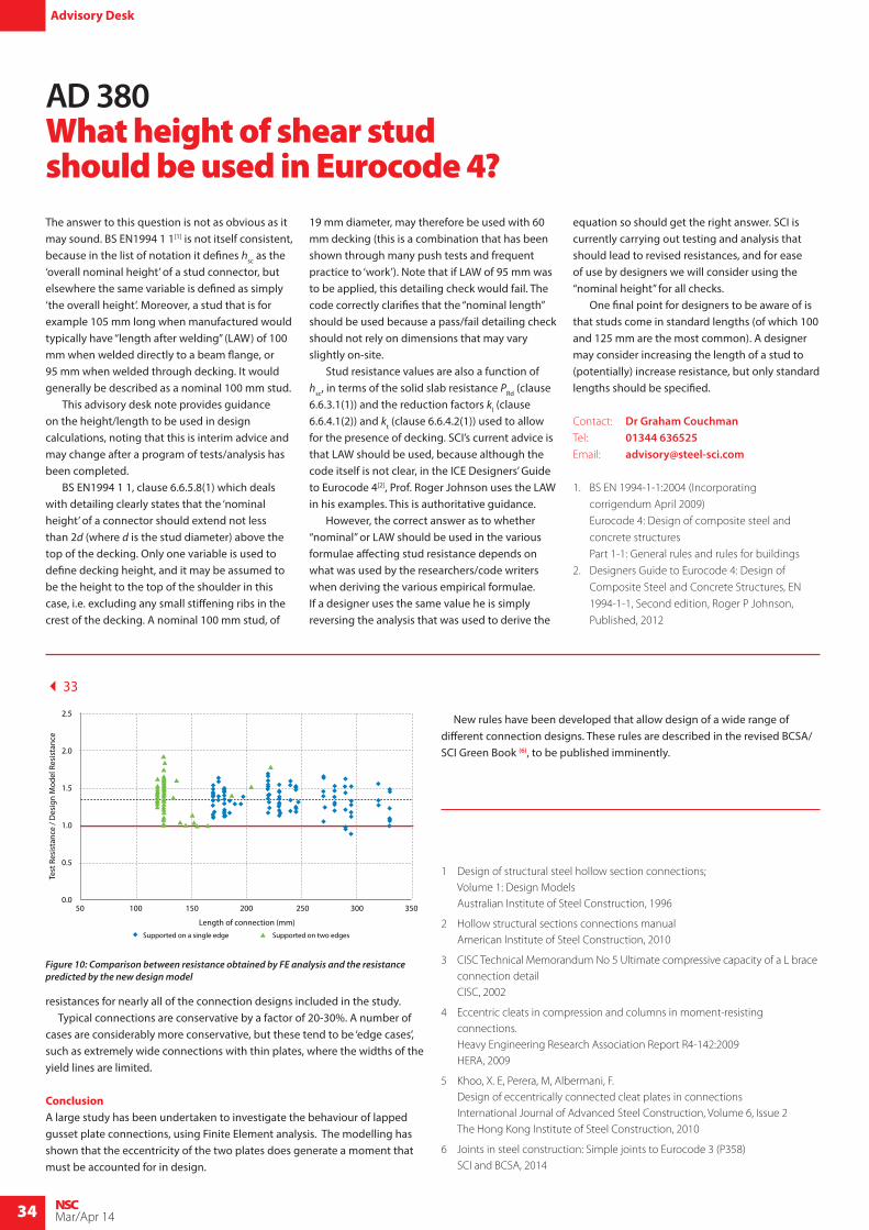
It can be seen that model is accurate for all of the connections in the study. All resistances calculated using the model are within 10-20% of the resistance from the tests. Figure 10 (over page) shows the comparison between the FE results and the new design model. It can be seen that the new design model predicts conservative
eo
Lc,1
Lc,La
pLc
,2
Figure 8: Equivalent ‘frame’ for analysis using the new method, and the bending moment diagram arising
NRd,tab =wtab fy,tabttab
2
5 × kamp × 0.5 (tguss + ttab) μtab + ttab[ ]
NRd,guss =wgussfy,gusstguss
2
5 × kamp × 0.5 (tguss + ttab) μguss + tguss[ ]
150 170 190 210 230 250 270 290 310 330 350
1.4
1.2
1.0
0.8
0.6
0.4
0.2
0.0
Length of connection (mm)
Test
Res
ista
nce
/ Des
ign
Mod
el R
esis
tanc
e
Figure 9: Comparison between resistance obtained by test results and the resistance predicted by the new design model
34
34 NSCMar/Apr 14
resistances for nearly all of the connection designs included in the study. Typical connections are conservative by a factor of 20-30%. A number of cases are considerably more conservative, but these tend to be ‘edge cases’, such as extremely wide connections with thin plates, where the widths of the yield lines are limited.
ConclusionA large study has been undertaken to investigate the behaviour of lapped gusset plate connections, using Finite Element analysis. The modelling has shown that the eccentricity of the two plates does generate a moment that must be accounted for in design.
New rules have been developed that allow design of a wide range of different connection designs. These rules are described in the revised BCSA/SCI Green Book (6), to be published imminently.
Advisory Desk
The answer to this question is not as obvious as it may sound. BS EN1994 1 1[1] is not itself consistent, because in the list of notation it defines hsc as the ‘overall nominal height’ of a stud connector, but elsewhere the same variable is defined as simply ‘the overall height’. Moreover, a stud that is for example 105 mm long when manufactured would typically have “length after welding” (LAW) of 100 mm when welded directly to a beam flange, or 95 mm when welded through decking. It would generally be described as a nominal 100 mm stud. This advisory desk note provides guidance on the height/length to be used in design calculations, noting that this is interim advice and may change after a program of tests/analysis has been completed. BS EN1994 1 1, clause 6.6.5.8(1) which deals with detailing clearly states that the ‘nominal height’ of a connector should extend not less than 2d (where d is the stud diameter) above the top of the decking. Only one variable is used to define decking height, and it may be assumed to be the height to the top of the shoulder in this case, i.e. excluding any small stiffening ribs in the crest of the decking. A nominal 100 mm stud, of
19 mm diameter, may therefore be used with 60 mm decking (this is a combination that has been shown through many push tests and frequent practice to ‘work’). Note that if LAW of 95 mm was to be applied, this detailing check would fail. The code correctly clarifies that the “nominal length” should be used because a pass/fail detailing check should not rely on dimensions that may vary slightly on-site. Stud resistance values are also a function of hsc, in terms of the solid slab resistance PRd (clause 6.6.3.1(1)) and the reduction factors kl (clause 6.6.4.1(2)) and kt (clause 6.6.4.2(1)) used to allow for the presence of decking. SCI’s current advice is that LAW should be used, because although the code itself is not clear, in the ICE Designers’ Guide to Eurocode 4[2], Prof. Roger Johnson uses the LAW in his examples. This is authoritative guidance. However, the correct answer as to whether “nominal” or LAW should be used in the various formulae affecting stud resistance depends on what was used by the researchers/code writers when deriving the various empirical formulae. If a designer uses the same value he is simply reversing the analysis that was used to derive the
equation so should get the right answer. SCI is currently carrying out testing and analysis that should lead to revised resistances, and for ease of use by designers we will consider using the “nominal height” for all checks. One final point for designers to be aware of is that studs come in standard lengths (of which 100 and 125 mm are the most common). A designer may consider increasing the length of a stud to (potentially) increase resistance, but only standard lengths should be specified.
Contact: Dr Graham CouchmanTel: 01344 636525Email: [email protected]
1. BS EN 1994-1-1:2004 (Incorporating
corrigendum April 2009)
Eurocode 4: Design of composite steel and
concrete structures
Part 1-1: General rules and rules for buildings
2. Designers Guide to Eurocode 4: Design of
Composite Steel and Concrete Structures, EN
1994-1-1, Second edition, Roger P Johnson,
Published, 2012
AD 380 What height of shear stud should be used in Eurocode 4?
1 Design of structural steel hollow section connections; Volume 1: Design Models Australian Institute of Steel Construction, 1996
2 Hollow structural sections connections manual American Institute of Steel Construction, 2010
3 CISC Technical Memorandum No 5 Ultimate compressive capacity of a L brace connection detail CISC, 2002
4 Eccentric cleats in compression and columns in moment-resisting connections. Heavy Engineering Research Association Report R4-142:2009 HERA, 2009
5 Khoo, X. E, Perera, M, Albermani, F. Design of eccentrically connected cleat plates in connections International Journal of Advanced Steel Construction, Volume 6, Issue 2 The Hong Kong Institute of Steel Construction, 2010
6 Joints in steel construction: Simple joints to Eurocode 3 (P358) SCI and BCSA, 2014
50 100 150 200 250 300 350
2.5
2.0
1.5
1.0
0.5
0.0
Length of connection (mm)
Test
Res
ista
nce
/ Des
ign
Mod
el R
esis
tanc
e
Supported on a single edge Supported on two edges
Figure 10: Comparison between resistance obtained by FE analysis and the resistance predicted by the new design model
33