Embed Size (px)
Citation preview

1 | P a g e
Design of Internal Combustion Engine

2 | P a g e
The Cylinder and Cylinder liner:-
The cylinders are usually made of cast iron or cast steel.
The cylinder liner are in the following two types.
Design of the cylinder:
Bore and Length of the cylinder.
From the power idecated from the cylinder
wattN
x
nlD
IP
BPm
604imepIP power Indecated The
efficiency mechanical The
2
cylinder engine ofNumper isn
rpmin engine theof Speed is N
mmin stroke ofLength is l
mmin boreCylinder is D
N/mmin pressure effectivemean indecated is imep
:
2
where
2D to1.25D taken generally is stroke ofLength The
:
Note
lo
Sothat
1.15 L Cylinder fLength The
:
3 | P a g e
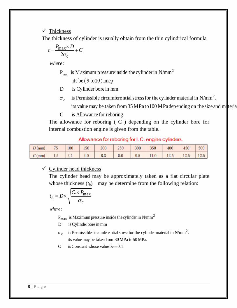
Thickness
The thickness of cylinder is usually obtain from the thin cylindrical formula
CDP
tc
2
max
reboringfor Allowance is C
material. and size on the depending MPa 100 toMPa 35 from taken bemay valueits
.N/mmin materialcylinder for the stress ntialcircumfere ePermissibl is
mmin boreCylinder is D
imep ) 10 to9 ( be its
N/mmin cylinder theinside pressure Maximum is P
:
2
2
max
c
where
The allowance for reboring ( C ) depending on the cylinder bore for
internal combustion engine is given from the table.
Cylinder head thickness
The cylinder head may be approximately taken as a flat circular plate
whose thickness (th) may be determine from the following relation:
ch
PCDt
max.
0.1 be valuehoseConstant w is C
MPa. 50 toMPa 30 from taken bemay valueits
.N/mmin materialcylinder for the stress ntialcircumfere ePermissibl is
mmin boreCylinder is D
N/mmin cylinder theinside pressure Maximum is P
:
2
2max
c
where

4 | P a g e
Cylinder flange and stude
The cylinders are cast integral with the upper half of the crank case
or they are attached to the crank case by means of flange with
studs or bolts and nuts.
The cylinder flange is integral with the cylinder and should be
made thicker than the cylinder wall.
The flange thickness should be taken as 1.2 t to 1.4 t, where t is the
cylinder wall thickness.
The diameter of studs or bolts may be obtained by equating the gas
load due to the maximum pressure in the cylinder to the resisting
force offered by all the studs or bolts, mathematically.
40.02D and 4D01.0
)(n be studs ofnumber theTake s
sn
max
22
44 Force Resistance PDdn tss
mmin stud ofdiameter Minor or Core is d
MPa. 70 toMPa 35 from taken bemay valueits
.N/mmin materialcylinder for the stress Tensile is
mmin boreCylinder is D
N/mmin cylinder theinside pressure Maximum is P
:
s
2
2max
t
where
d 84.0d
be (d)diameter stude The
s

5 | P a g e
Piston:-
The piston is a disc which reciprocates within a cylinder.
The main function of piston is to receive the impulse from the expanding gas
and to transmit the energy to the crankshaft through the connecting rod.
The most commonly used materials for pistons of IC engine are cast iron,
cast aluminium, forged aluminium, cast steel and forged steel.

6 | P a g e
Design of the Piston:
Piston head or Crown
The thickness of piston head (tH) according to Grashoff,s Formula is given
IronCast Nickelor Alloy Aluminumfor MPa 90 toMPa 50
andIron cast Gray for MPa 40 to35MPa be stress tensileis :where
16
P3 )(t Thickness
2max
H
t
t
D
Also the thickness of piston head should be quickly transferred heat from
combustion of fuel to the cylinder walls. So that piston head as flat circular
plate, have thickness by
Cin piston of edge at the re temperatuis T
Cin piston ofcenter at re temperatuis T
Aluminiumfor W/mC147.75 andiron Cast for W/mC46.6 beit ty conductivi thermalisk
0.05 beconstant is C
kg/kW.sunit its fuel of mass is m
fuel dieselfor kJ/kg 45000 and fuel petrolfor kJ/kg 47000 beit fuel of valuecalorific is CV.
cylinderfor Power Brake is .:
CmCV.BP. H
by Watt rate flowHeat is :where
Tk12.56
H )(t Thickness
oE
oC
Watt
H
BPwhere
H
Tmm
HC
From the two equation take the large thickness value.

7 | P a g e
Piston Rib
The piston rib may be four.
Its thickness (tR)
2
3 )(t Thickness R
HH t to
t
Piston Rings.
The piston rings used to impart the necessary radial pressure to
maintain the seal between the piston and the cylinder bore
The piston rings usually made of grey cast iron or alloy cast iron
because of its good wearing properties.
The piston rings are of the following types:
o Compression rings or Pressure rings
o Oil control rings or oil scraper
The radial thickness of the ring be

8 | P a g e
IronCast for MPa 110 to85 beit stress tensileis
N/mm 0.042 to0.025 beit allcylinder won gas of pressure is :
P3D )(t Thickness Radial
t
2
w1
w
t
Pwhere
The axial thickness of the ring be
R2
112
n also 10
)(t b thicknessminimum the:where
70 )(t Thickness Axial
R
n
D
to tt.
The distance from top of piston to first ring groove:
HH ttot 2.1 b1
Width of other rings:
222 75.0b ttot
The gap between two ends of ring:
111 4 5.3G ttot
The gap when ring in cylinder:
DtoD 0.004 002.0G2
Piston Barrel
It is a cylindrical portion of the piston.
mmtbringsofdipthradialwhere 4.0 :
t35.0 to t25.0)(t thicknesswall
mm 4.5bD .030 )(t Thickness
1
334
3

9 | P a g e
Piston Skirt
The portion of the piston below the ring section is known as piston
skirt.
The side thrust ( R ) on the cylinder liner is usually taken as 1/10 of
the maximum gas load on the piston.
2
2max
/45.0
41.0
:
)(Length
mmNbeittakepressureBearingP
DPR
where
DP
Rl
b
b
122 )34( L
land Top section ring ofLength skirt ofLength L) (piston oflength Total
bbtl
Piston Pin
The piston pin is used to connect the piston and the connecting rod.
The material used for the piston pin is usually case hardened steel
alloy containing nickel, chromium, molybdenum or vanadium having
tensile stress from 710 MPa to 910 MPa.

10 | P a g e
Where:
do outside diameter of pin mm
l1 length of pin in bush of small end of connecting
rod
mm
Pb1 Bearing pressure at small end of connecting rod its value for
bronze is 25
N/mm2
So that:-
11max2
4 pin piston on the Load ldPPD ob
oi ddDl 6.0 and 45.0 : Where 1

11 | P a g e
Connecting Rod:
It is the intermediate member between the piston and crankshaft.
Its primary function is to transmit the push and pull from the piston pin to
the crankpin and convert the reciprocating motion of the piston into the
rotary motion of the crank.
It consists of a long shank, small end and a big end.
The material mostly used for connecting rods varies from mild carbon steels
with tensile stress 650 MPa to alloy steel with tensile stress 1050 MPa.

12 | P a g e
Design of Connecting Rod
Dimension of cross-section of connecting rod
Thckness of flange and web of the section:
2
c
1
FsFc (Wc) Load Buckling
Kxx
La
A
ronast 1600/1
ron wrought 9000/1
7500/1 .
78.1 sec Kxx
211sec
4 Fc
Fs
:where
max2
icfor
ifor
steelmeeldforConsta
tA
Ixxaxisxabouttionofgyrationofradius
ttionofareaA
length cting rod L Conne
PDπ
F rod Fconnecting Force of
seftyFactor of
LC
HtoHHendsmallnearDepth
HtoHHendbignearDepth
.90 75.0)(
25.1 1.1)(
:also
2
1
tHoDepth
tBw
5)(section theofheight r
4)(section theofidth
:also

13 | P a g e
Dimension of the crankpin at the big end bearing and piston pin at small end
bearing.
The piston pin bearing is usually a phosphor bronze of about 3 mm thickness
and the allowable bearing pressure (Pbc)be 10.5 N/mm2 to 15 N/mm
2.
mm d1.3 bearing, end bigat pin crank oflength is
mm bearing, end bigat pin crank ofdiameter is
:
)(13
pressure Bearing x area Projected force gas .max
c
2
c
c
cL
L
l
d
where
dF
F
mm d2 ,pin piston oflength is
mm ,pin piston ofdiameter is
:
)(30
pressure Bearing x area Projected force gas .max
p
2
p
p
pL
L
l
d
where
dF
F
Size of bolts for securing the big end cap:
The bolts and the big end cap are subjected to tensile force which
corresponds to the inertia force of the reciprocating parts at the top dead
center on the exhaust stroke.
Take the tensile strength of the bolts material be 60 N/mm2
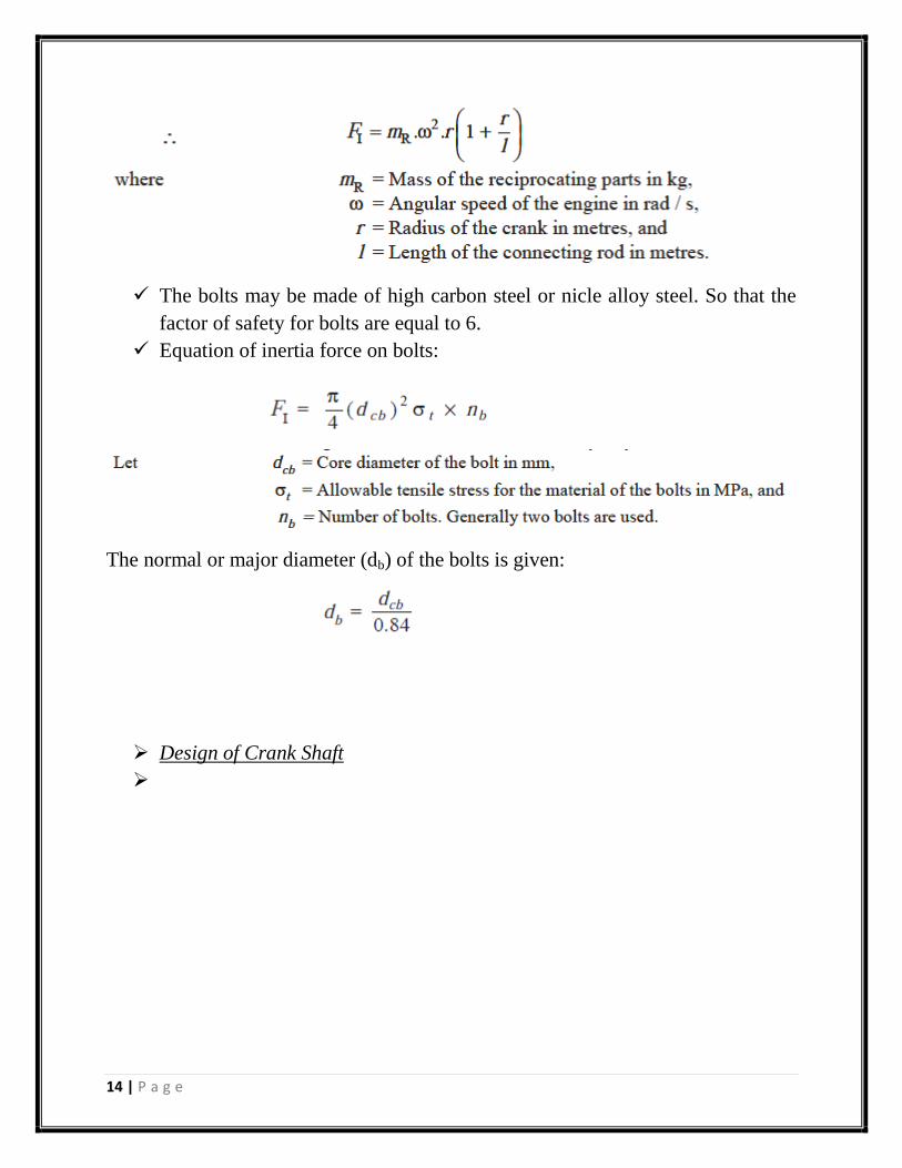
The enertia force of reciprocating parts FI
Where: ϴ is crank angle which equal to Zero at the top dead center.
14 | P a g e
The bolts may be made of high carbon steel or nicle alloy steel. So that the
factor of safety for bolts are equal to 6.
Equation of inertia force on bolts:
The normal or major diameter (db) of the bolts is given:
Design of Crank Shaft