Embed Size (px)
Citation preview
O&SB2010 “Open and Sustainable Building” – Chica, Elguezabal, Meno & Amundarain (Eds.) © 2010, Labein -TECNALIA. ISBN 978-84-88734-06-8
DESIGN OF HIGH-RISE MODULAR OPEN BUILDINGS Lawson, Mark R SCI Professor of Construction Systems, University of Surrey, UK,
ABSTRACT Modular construction is widely used for residential buildings of 4 to 8 storeys. In the context of open building systems, modular construction provides a systemised approach to design in which the benefits of prefabrication are maximised. There is pressure to extend this form of construction to more than 12 storeys for residential buildings. This paper presents a review of modular technologies, and describes load tests and analysis on light steel modular walls in compression that are used to justify the use of light steel technology to support higher loads. However, the effect of installation and geometric inaccuracies must be taken into account in the design of modular buildings. The cumulative out of verticality should not exceed 8mm per module in a vertical group with a maximum of 50mm relative to ground datum. Using these geometric tolerances, the notional horizontal force used to evaluate stability of a group of modules should be taken as a minimum of 1% of the applied vertical load on the modules. Robustness to accidental load effects is important in all high-rise buildings and it is proposed that the tie force in the connections between modules should be taken as not less than 30% of the total vertical load applied to the module, and not less than 30 kN in both directions. Keywords: Modular; Structures; Stability; Steel; Tolerances
438
INTRODUCTION Modular construction comprises pre-fabricated room-sized volumetric units that are normally fully fitted out in manufacture and are installed on site as load-bearing ‘building blocks’. Their primary advantages are:
• Economy of scale in manufacturing of multiple repeated units.
• Speed of installation on site.
• Improved quality and accuracy in manufacture
The current range of applications of modular construction is in cellular-type buildings such as hotels, student residences, military accommodation, and social housing, where the module size is compatible with manufacturing and transportation requirements. The current application of modular construction of all types is reviewed in a recent Steel Construction Institute publication (Lawson). A paper (Lawson, Ogden et al) describes the mixed use of modules, panels and steel frames to create more adaptable building forms.
There are two generic forms of modular construction, which affects directly their range of application:
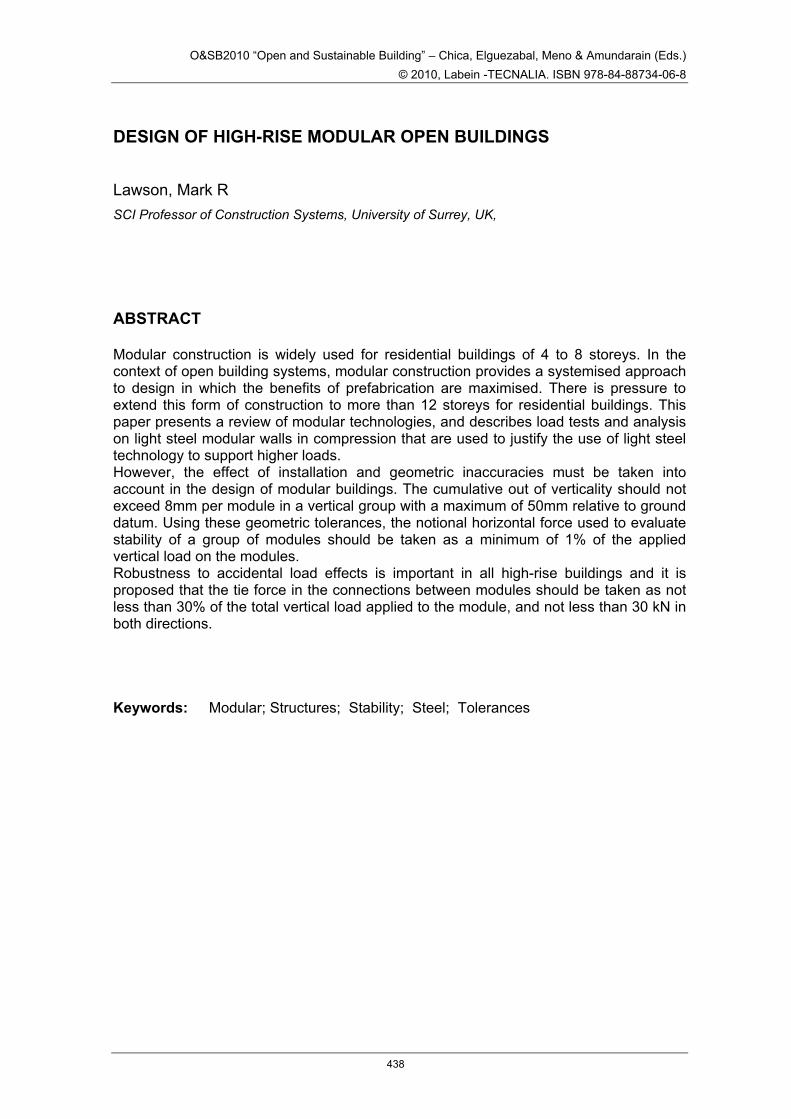
• Load-bearing modules in which loads are transferred through the side walls of the modules – see 0
• Corner supported modules in which loads are transferred via edge beams to corner posts
In the first case, the compression resistance of the walls (comprising light steel C sections at 300 to 600 mm spacing) is crucial. Current heights of modular buildings of this type are limited to 4 to 8 storeys, depending on the size and spacing of the C sections.
In the second case, the compression resistance of the corner posts is the controlling factor and for this reason, Square Hollow Sections (SHS) are often used due to their high buckling resistance. Building heights are limited only by the size of the SHS that may be used for a given module size (150 × 150 × 12.5 SHS is the maximum sensible size of these posts).
Figure 1 Partially open sided module with load-bearing walls (courtesy PCKO Architects)
Resistance to horizontal forces, such as wind loads and robustness to accidental actions, become increasingly important with the scale of the building. The strategies
439
employed to ensure adequate stability of modular assemblies, as a function of the building height, are:
• Diaphragm action of boards or bracing within the walls of the modules – suitable for 4-6 storey buildings
• Separate braced structure using hot rolled steel members located in the lifts and stair area or in the end gables – suitable for 6-10 storeys
• Reinforced concrete or steel plated core – suitable for taller buildings
Modules are tied at their corners so that they act together to transfer wind loads and provide alternative load paths in the event of one module being severely damaged. A recent paper (Lawson, Byfield) reviews the robustness requirements for modular construction based on ‘localisation of damage’ in which modules are removed individually to assess the ability of the rest of the modular assembly to support the applied loads at the accidental limit state.
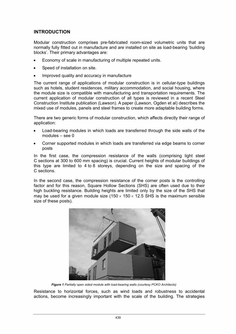
For taller buildings, questions of compression resistance and overall stability require a deeper understanding of the behaviour of the light steel C sections in load-bearing walls and of the robust performance of the inter-connection between the modules. A further issue is that of installation and manufacturing tolerances, which cause eccentricities in the compression load path and also lead to additional horizontal forces applied to the modules. HIGH-RISE BUILDING FORMS USING MODULAR CONSTRUCTION Modular construction is conventionally used for cellular buildings up to 8 storeys high. However, there is pressure to extend this technology up to 15 storeys or more. One technique is to cluster modules around a core to create high-rise buildings without a separate structure in which the modules are designed to resist compression and the core provides overall stability. This concept has been used on one major project called Paragon in west London, shown in Figure 2, in which the modules were constructed with load-bearing corner posts.
Figure 2 Modular building stabilised by a concrete core (courtesy Caledonian Building Systems)
440
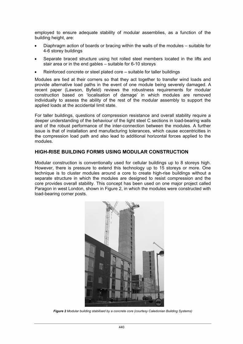
An adaptation of this technology is to design a ‘podium’ or platform structure on which the modules are placed. In this way, open space is provided for retail or commercial use or car parking. Support beams should align with the walls of the modules and columns are typically arranged on a 6 to 8 m grid (7.2 m is optimum for car parking), as shown in Figure 3.
4.5 m
6 m
2.8 m
3 - 3.6 m
Modules
Core forstairs/lifts
300
300Span of 12 - 18 m
Figure 3 Modules supported by cellular steel beams acting as a podium
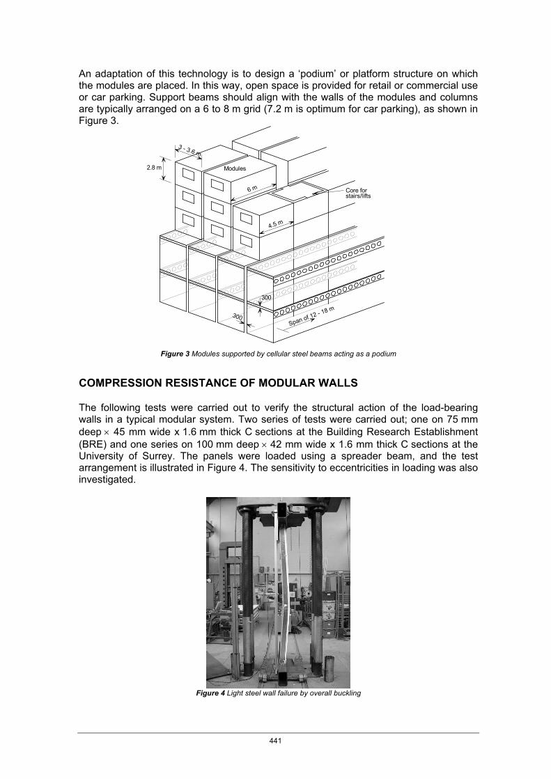
COMPRESSION RESISTANCE OF MODULAR WALLS The following tests were carried out to verify the structural action of the load-bearing walls in a typical modular system. Two series of tests were carried out; one on 75 mm deep × 45 mm wide x 1.6 mm thick C sections at the Building Research Establishment (BRE) and one series on 100 mm deep × 42 mm wide x 1.6 mm thick C sections at the University of Surrey. The panels were loaded using a spreader beam, and the test arrangement is illustrated in Figure 4. The sensitivity to eccentricities in loading was also investigated.
Figure 4 Light steel wall failure by overall buckling
441
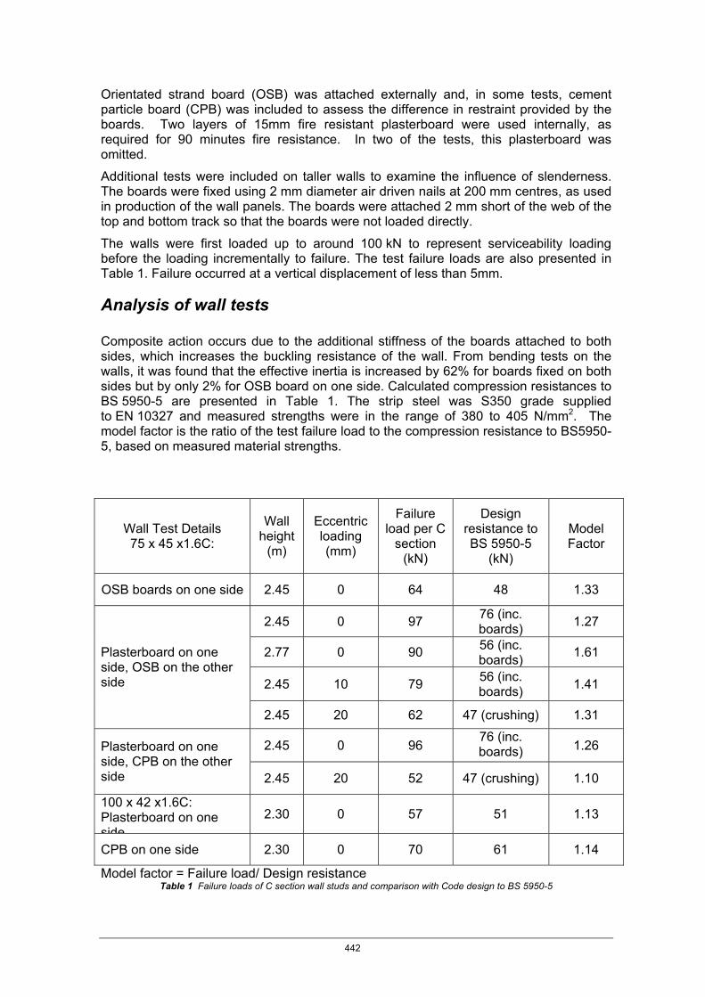
Orientated strand board (OSB) was attached externally and, in some tests, cement particle board (CPB) was included to assess the difference in restraint provided by the boards. Two layers of 15mm fire resistant plasterboard were used internally, as required for 90 minutes fire resistance. In two of the tests, this plasterboard was omitted.
Additional tests were included on taller walls to examine the influence of slenderness. The boards were fixed using 2 mm diameter air driven nails at 200 mm centres, as used in production of the wall panels. The boards were attached 2 mm short of the web of the top and bottom track so that the boards were not loaded directly.
The walls were first loaded up to around 100 kN to represent serviceability loading before the loading incrementally to failure. The test failure loads are also presented in Table 1. Failure occurred at a vertical displacement of less than 5mm.
Analysis of wall tests Composite action occurs due to the additional stiffness of the boards attached to both sides, which increases the buckling resistance of the wall. From bending tests on the walls, it was found that the effective inertia is increased by 62% for boards fixed on both sides but by only 2% for OSB board on one side. Calculated compression resistances to BS 5950-5 are presented in Table 1. The strip steel was S350 grade supplied to EN 10327 and measured strengths were in the range of 380 to 405 N/mm2. The model factor is the ratio of the test failure load to the compression resistance to BS5950-5, based on measured material strengths.
Wall Test Details 75 x 45 x1.6C:
Wall height
(m)
Eccentric loading (mm)
Failure load per C
section (kN)
Design resistance to BS 5950-5
(kN)
Model Factor
OSB boards on one side 2.45 0 64 48 1.33
2.45 0 97 76 (inc. boards) 1.27
2.77 0 90 56 (inc. boards) 1.61
2.45 10 79 56 (inc. boards) 1.41
Plasterboard on one side, OSB on the other side
2.45 20 62 47 (crushing) 1.31
2.45 0 96 76 (inc. boards) 1.26 Plasterboard on one
side, CPB on the other side 2.45 20 52 47 (crushing) 1.10
100 x 42 x1.6C: Plasterboard on one side
2.30 0 57 51 1.13
CPB on one side 2.30 0 70 61 1.14
Model factor = Failure load/ Design resistance Table 1 Failure loads of C section wall studs and comparison with Code design to BS 5950-5
442

The stiffening effect of the boards leads to a reduction in slenderness and increase in buckling resistance. Using the measured increase in bending stiffness due to attachment of the OSB and plasterboards, the effective slenderness of the bare C section is reduced by 22%. For a 2.45 m high wall, the slenderness was 79 in the major axis direction, and so the effective slenderness becomes 0.78 × 79 = 62, which gives a buckling strength of pc = 263 N/mm2. The calculated compression resistance was 67 kN, which is 70% of the test result of 97 kN. This suggests that the buckling curve used for cold formed sections is conservative. In addition, local buckling of the flanges of C section may be reduced by the attachment of the boards, which increases the effectiveness of the cross-section.
The eccentricity of load application using a plate below the wall accentuates local crushing, as well as overall buckling. The crushing resistance may be taken into account by considering a reduced compression area, Aeff. Because the buckling resistance is approximately 70% of the crushing resistance, it follows that buckling will occur first unless the crushing resistance is reduced by over 30%. A 10 mm eccentricity caused a 19% reduction in load capacity and a 20 mm eccentricity caused a 36% reduction in capacity.
The series of tests on walls using 100 x1.6C sections with boards on one side showed that minor axis buckling is prevented for 1.6mm thick steel, but the increase in compression resistance relative to BS 5950-5 was less than for the 75mm deep sections. STRUCTURAL ACTION OF GROUPS OF MODULES The structural behaviour of an assembly of modules is complex because of the influence of the tolerances that are implicit in the installation procedure, the multiple inter-connections between the modules, and the way in which forces are transferred to the stabilising elements such as vertical bracing or core walls. The key factors to be taken into account in the design of high-rise modular buildings are: • The influence of initial eccentricities and construction tolerances on the additional
forces and moments in the walls of the modules.
• Application of the design standard for steelwork to this relatively new technology.
• Second order effects due to sway stability of the group of modules.
• Mechanism of force transfer of horizontal loads to the stabilising system.
• Robustness to accidental actions for modular systems
These aspects are considered as follows: Influence of constructional tolerances For structural steel frames, the UK National Structural Steelwork Specification for Building Construction, NSSA (BSCA) presents the maximum out-of-verticality of a single column as δH ≤ height/600, but ≤ 5 mm per storey. Furthermore, for buildings of more than 10 storeys high, the out-of-verticality over the total height is limited to a maximum of 50 mm. Eurocode 3-1-1Clause 5.3.2 (EN 1993-1-1) limits the out-of-verticality of a single column to L/200, but this is reduced by a factor of 2/3 when considering the average out-of-verticality over a number of storeys (i.e. δH ≤ L/300). The permitted out of verticality of a whole structure is obtained by multiplying this value for a single column by a factor of
443
5.0
)11(5.0 ⎥⎦⎤
⎢⎣⎡ +
mfor m columns in a group horizontally. The result tends to δH ≤ L/420,
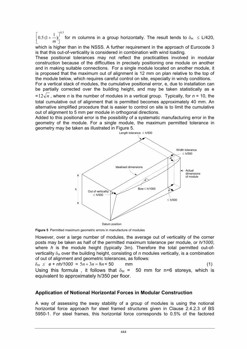
which is higher than in the NSSS. A further requirement in the approach of Eurocode 3 is that this out-of-verticality is considered in combination with wind loading. These positional tolerances may not reflect the practicalities involved in modular construction because of the difficulties in precisely positioning one module on another and in making suitable connections. For a single module located on another module, it is proposed that the maximum out of alignment is 12 mm on plan relative to the top of the module below, which requires careful control on site, especially in windy conditions. For a vertical stack of modules, the cumulative positional error, e, due to installation can be partially corrected over the building height, and may be taken statistically as e = n12 , where n is the number of modules in a vertical group. Typically, for n = 10, the total cumulative out of alignment that is permitted becomes approximately 40 mm. An alternative simplified procedure that is easier to control on site is to limit the cumulative out of alignment to 5 mm per module in orthogonal directions. Added to this positional error is the possibility of a systematic manufacturing error in the geometry of the module. For a single module, the maximum permitted tolerance in geometry may be taken as illustrated in Figure 5.
≤
≤ h/500
≤ h/500
≤ h/500
≤ h/500
h Bow h/1000Out of verticality
Datum position
Idealised dimensionsActualdimensionsof module
Width tolerance
Length tolerance
Figure 5 Permitted maximum geometric errors in manufacture of modules
However, over a large number of modules, the average out of verticality of the corner posts may be taken as half of the permitted maximum tolerance per module, or h/1000, where h is the module height (typically 3m). Therefore the total permitted out-of-verticality δH over the building height, consisting of n modules vertically, is a combination of out of alignment and geometric tolerances, as follows: δH ≤ e + nh/1000 = nnn 835 =+ < 50 mm (1) Using this formula , it follows that δH = 50 mm for n=6 storeys, which is equivalent to approximately h/350 per floor. Application of Notional Horizontal Forces in Modular Construction A way of assessing the sway stability of a group of modules is using the notional horizontal force approach for steel framed structures given in Clause 2.4.2.3 of BS 5950-1. For steel frames, this horizontal force corresponds to 0.5% of the factored
444
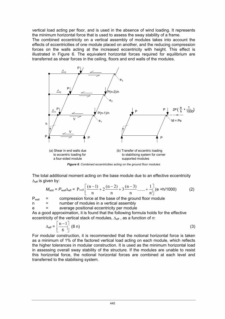
vertical load acting per floor, and is used in the absence of wind loading. It represents the minimum horizontal force that is used to assess the sway stability of a frame. The combined eccentricity on a vertical assembly of modules takes into account the effects of eccentricities of one module placed on another, and the reducing compression forces on the walls acting at the increased eccentricity with height. This effect is illustrated in Figure 6. The equivalent horizontal forces required for equilibrium are transferred as shear forces in the ceiling, floors and end walls of the modules.
1
2
3
e
e M = Pe
e
3
1
2
P P
P P
V
Vh
P
(a) Shear in end walls due to eccentric loading for a four-sided module
P(n-2)/n
P(n-1)/n
P
P
P 2P +e 1
(b) Transfer of eccentric loading to stabilising system for corner supported modules
h 1000( )
Figure 6: Combined eccentricities acting on the ground floor modules
The total additional moment acting on the base module due to an effective eccentricity Δeff is given by:
Madd = PwallΔeff = ⎥⎦⎤
⎢⎣⎡ +
−+
−+
−n1.......
n)3n(3
n)2n(2
n)1n(P wall (e +h/1000) (2)
Pwall = compression force at the base of the ground floor module n = number of modules in a vertical assembly e = average positional eccentricity per module As a good approximation, it is found that the following formula holds for the effective eccentricity of the vertical stack of modules, Δeff , as a function of n:
Δeff = ⎥⎦⎤
⎢⎣⎡ −
61n
(8 n) (3)
For modular construction, it is recommended that the notional horizontal force is taken as a minimum of 1% of the factored vertical load acting on each module, which reflects the higher tolerances in modular construction. It is used as the minimum horizontal load in assessing overall sway stability of the structure. If the modules are unable to resist this horizontal force, the notional horizontal forces are combined at each level and transferred to the stabilising system.
445

Forces at module inter-connections
The structural inter-actions within a group of modules are complex. The horizontal forces may be transferred by tension and compression forces in the ties at the corners of the modules by utilising the diaphragm action of the base and ceiling of the modules.
Shear forces may be transferred through the continuous corridor members and the connection of the modules to the corridor may be made by a detail of the form of Figure 7. The extended plate is screw fixed on site to the corridor members and is bolted to the re-entrant corners between the modules so that it also acts as a tie plate. This detail is not used to provide vertical support to the corridor, which is supported on continuous angles as part of the manufacture of the modules.
Figure 7 Connection between the corridor cassette and modules- sketch detail (left) and actual detail (right)
80
7030 gap
Bolt hole
Upper module
Lower module
446
Robustness to accidental damage
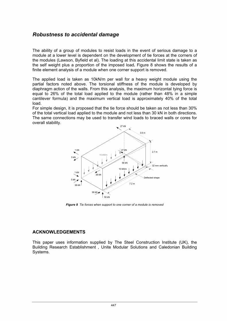
The ability of a group of modules to resist loads in the event of serious damage to a module at a lower level is dependent on the development of tie forces at the corners of the modules (Lawson, Byfield et al). The loading at this accidental limit state is taken as the self weight plus a proportion of the imposed load. Figure 8 shows the results of a finite element analysis of a module when one corner support is removed.
The applied load is taken as 10kN/m per wall for a heavy weight module using the partial factors noted above. The torsional stiffness of the module is developed by diaphragm action of the walls. From this analysis, the maximum horizontal tying force is equal to 26% of the total load applied to the module (rather than 48% in a simple cantilever formula) and the maximum vertical load is approximately 40% of the total load. For simple design, it is proposed that the tie force should be taken as not less than 30% of the total vertical load applied to the module and not less than 30 kN in both directions. The same connections may be used to transfer wind loads to braced walls or cores for overall stability.
27 kN
5 kN
1 kN
56 kN
27 kN
5 kN
1 kN
38 kN
38 kN
50 kN
38 kN
3.6 m
2.7 m
10 kN/m
10 kN/m
Deflected shape
7.2 m
32 mm vertically
Figure 8 Tie forces when support to one corner of a module is removed
ACKNOWLEDGEMENTS This paper uses information supplied by The Steel Construction Institute (UK), the Building Research Establishment , Unite Modular Solutions and Caledonian Building Systems.
447
REFERENCES
BCSA, National Structural Steelwork Specification for Building Construction British Constructional Steelwork Association, 5rd Edition, 2007
BS 5950 Part 1: Structural Use of Steelwork in Building. Code of Practice for Design of Simple and Continuous Construction: Hot Rolled Sections, British Standards Institution, 2000
BS 5950 Part 5: Structural Use of Steelwork in Building. Code of Practice for Design of Thin Walled structures, British Standards Institution, 2000
EN 1993-1-1:Eurocode 3: Steel Structures- General Rules and Rules for Buildings,2004
EN 10327: Specification for continuously Hot-Dip Zinc Coated Structural Steel and Strip – Technical Delivery Conditions,2004
Lawson R.M. Building Design using Modules,The Steel Construction Institute P367, 2007
Lawson R.M., Byfield M ,Popo-Ola S and Grubb J ,Robustness of Light Steel Frames and Modular Construction, Proc. Inst. Civil Engineers, Buildings and Structures, Vol 161 SB1 February 2008
Lawson R.M., Ogden R.G., Pedreschi R, Popo-Ola S and Grubb J Developments in Pre-fabricated Systems in Light Steel and Modular Construction The Structural Engineer. Vol 83 N0 6, 15 March 2005 p 28-35
448


![[PSS 2A-1Z11 A] Pressure Seals for Use with I/A Series ...€¦ · RECESSED DIAPHRAGM SEALS Recessed diaphragm seal assemblies are available in flanged, threaded, and in-line weld](https://img.dokumen.tips/doc/110x75/5f759f42347cf3713b4a073e/pss-2a-1z11-a-pressure-seals-for-use-with-ia-series-recessed-diaphragm-seals.jpg)