Embed Size (px)
Citation preview

DESIGN OF HELICAL SHAPED HEATING COIL AND LOAD CIRCUIT FOR H. F. MIRROR INVERTER BASED
INDUCTION HEATER PRADIP KUMAR SADHU
Department of Electrical Engg., Indian School of Mines, Dhanbad,Jharkhand,India,826004
[email protected] www.ismdhanbad.ac.in
NITAI PAL Department of Electrical Engg., Indian School of Mines,
Dhanbad,Jharkhand,India,826004 [email protected] www.ismdhanbad.ac.in
ANANYO BHATTACHARYA Department of Electrical Engg., Indian School of Mines,
Dhanbad,Jharkhand,India,826004 [email protected]
www.ismdhanbad.ac.in
ATANU BANDYOPADHYAY
Department of Electrical Engg., Asansol Engg. College, Asansol,West Bengal,India,713305
[email protected] www.aecwb.edu.in
Abstract:
A high frequency series resonant mirror inverter based induction-heated system has been developed with helical shaped heating coil in its primary. To reduce the skin effect loss & proximity loss, the heating coil is made of litz wire. The coil inductance & a.c resistance have been determined using analytical method under on load conditions. With the different secondary metallic objects in its secondary the determined values of inductance & a.c resistance have been found to change significantly. For industrial applications stainless still is preferred due to its high permeability and resistivity. The lab prototype of induction heated system is experimented with water as fluid & stainless still plates as secondary metallic object and for different frequencies efficiencies have been obtained. Finally to decide the load structure the system is tested with single layer, double layer & triple layer metallic sheets made of different metal combinations.
Keywords: mirror inverter, litz wire, a.c. resistance, metallic object, system efficiency
1. Introduction
In general, induction heating is a contactless method of generating heat energy in a magnetically conductive material by producing both eddy current losses and hysteresis losses in the work piece from an external variable high-frequency PWM inverter. The high-frequency magnetic field is usually established by a magnetic coil wrapped around the work piece or held parallel to the surface of the work piece. Resonant inverters are widely used for induction heating over wide frequency ranges from 4 kHz to 500 kHz (Pal, Sadhu and Chakrabarti, 2006). The inverter operating frequency selected for a particular application is based on the depth of heat penetration and on power conversion efficiency (Dawson & Jain, 1991). The variable high-frequency resonant inverter circuit using IGBT appears more efficient, compact in size and of faster response as compared to conventional electrical heating method (Wang, S.P, Nakaoka , M & Uchihoni, Y,1996). The amount of eddy current which is induced in the secondary metallic objects depends on the so many factors which are outlined as follows (Sadhu et al., 2001):
Pradip Kumar Sadhu et al. / International Journal of Engineering Science and Technology (IJEST)
ISSN : 0975-5462 Vol. 4 No.11 November 2012 4516

Material conductivity () : The conductivity of the material of the metal surface has a direct effect on the flow of eddy current. The higher the conductivity of the material the larger will be the flow of eddy currents on the surface.
Permeability of the material () : Permeability is the property of a material describing the ease with which it can give passage to magnetic flux. For non-ferrous metals such as copper, brass, aluminum etc. and for austenitic stainless steels, the permeability is almost the same as that of free space i.e. the relative permeability will be very close to unity. For ferrous metals, however, the value of relative permeability will be quite high, of the order of several hundred. The value of has a significant influence on the magnitude of the induced eddy current.
Operating frequency () : The response to eddy current is significantly affected by the frequency chosen. Fortunately, however, this is an item which can be easily controlled.
Geometry of the object : Practical heating surface is neither flat nor of infinite size. Besides, geometrical features such as curvature, edges, grooves etc. will exist and they all will affect the eddy current response. Also, if the material thickness be less than the corresponding effective depth of penetration then this will also unduly affect the eddy current produced.
Depth of penetration () : The eddy current density and hence the amount of heat produced, is greatest on the surface of the metal being heated and then declines with the depth. It is convenient to define mathematically the standard depth of penetration where the eddy current is 37% of its surface value and may be expressed as:
(1)
Equation (1) reveals that following are the factors that affect the depth of penetration.
(i) decreases with the increase of frequency (ii) increases with the increase of resistivity (iii) decreases with the increase of permeability.
With reference to the above analysis stainless steel is the best possible choice as a secondary metallic object in the high frequency resonant inverter based induction heated systems due to its very high permeability & conductivity .Therefore stainless steel is a preferred load material in the industrial application of induction heated systems. Also is a very cost effective material which makes its choice further easier.
This paper presents some developments in the process of induction heat flow through metallic package in non-metallic pipelines. The high frequency current source point image resonant inverter or mirror inverter(Sadhu, P. K., Chakrabarti, R. N., Chowdhury, S. P., 2001) fed fluid heating appliance is more acceptable than the conventional gas combustion type or others mainly from the point of view of better heat transfer under precise temperature management as well as improved heat energy storage and heat exchange processing of tank fluid heating in the pipeline systems. The other advantages are in clean processing, compactness, high reliability, quick response and the absence of any combustion waste. Besides, enrooting water through specially designed metallic assemblies will permit eddy-current based heating through electromagnetic induction. In this work a variable-frequency series-resonant PWM IGBT-based inverter system is introduced for induction heated pipeline fluid-heating appliance for industrial, medical, consumer and power plant applications.
In the present paper, first of all the proposed hardware industrial set up prototype is tested in different conditions & wave forms of various parameters have been recorded & verified with the waveforms obtained through software experiments. Thereafter with the same set up, efficiencies at different temperature settings have been determined & compared. Finally through real time experimental results different combinations of secondary metals are tested to constitute the appropriate load circuit for induction heater applicable for industrial application. Thorough real time experiments have been performed with high frequency inverter to optimize the performance of the present induction heated scheme & afterwards the suitability of secondary metallic object is decided.
2. The developed scheme
The electromagnetic induction based fluid heating appliance using the high-frequency series resonant inverter and its related system control technologies appears to attract interest in medical, chemical, mechanical and consumer heat energy utilization in the pipeline system (Sadhu, P. K., Chakrabarti, R. N., Chowdhury, S. P., 2008). Direct fluid heating based on electromagnetic induction principle can be done in two ways viz. skin effect heating in wall-surface of pipeline and package-in-pipeline internal eddy current heating. The latter
Pradip Kumar Sadhu et al. / International Journal of Engineering Science and Technology (IJEST)
ISSN : 0975-5462 Vol. 4 No.11 November 2012 4517

method seems an attractive concept incorporated in this topology. The eddy currents are induced in flow-through metallic package with a large number of heating surface incorporated into the non-metallic pipeline by means of an external working-coil fed from a high-frequency series resonant inverter operated by PWM scheme and whose ‘OFF’ time is more or less kept constant for different set temperature while the ‘ON’ time is increased for quicker rise in temperature. Fig.1 shows a schematic system configuration of electromagnetic induction fluid heating appliance based on high frequency mirror inverter.
Fig. 1 Schematic of induction heated electrical energy conversion in non-metallic pipe-line for industrial set-up.
The fluid-heating appliance used in the pipeline system is composed of a diode rectifier without smoothing filter so as to operate at power factor which is close to unity. For harmonic current compensation, a current-fed modified half bridge type series load resonant mirror inverter with a variable frequency variable power control is provided. A specially-designed electromagnetic induction fluid heating assembly with a metallic package to achieve eddy current heating in the pipe line system is incorporated into the non-metallic vessel. The working coil is wrapped around for generating high-frequency flux. This appliance is highly acceptable for fluid heat-transfer and delivery processing plants as well as heat energy storage and heat exchange processing because of clean, compact, efficient and smart response. From practical viewpoint, the above appliance seems cost-effective for induction-heated boiler, evaporator, hot water supplier and super heating unit in the pipeline system.
2.1 Mirror inverter based system
Fig. 2 shows the above system using a series resonant high-frequency mirror inverter with an active power filter. Now, the single point MN is stretched as shown in Fig. 3. The basic working of this configuration is very simple (Sadhu et al., 2005). The non-smooth D.C voltage is available across A & B points in the above-mentioned circuit. As explained there , the generated alternating current through the NM bar will also flow through the induction heating working coil ‘L’ which will generate alternating magnetic flux because it is connected in series. Fig.4 indicates a specially designed eddy current heated metallic package developed which is tightly incorporated into the nonmetallic vessel or tank in the pipeline. The mechanically processed thin stainless-steel layer package with many spots and fluid channels for cylindrical induction-heated assembly is demonstrated in Fig. 4.
Fig. 2 High-frequency mirror inverter circuit
Pradip Kumar Sadhu et al. / International Journal of Engineering Science and Technology (IJEST)
ISSN : 0975-5462 Vol. 4 No.11 November 2012 4518

Fig. 3 Equivalent circuit of high-frequency mirror inverter of fig. 2 (with MN point stretched)
Fig. 4 A specially-designed eddy current heated metallic package
Internal structure of this metallic package to be heated by eddy current losses is indicated in Fig. 5. When the fluid flows through the inherent package in the vessel or tank having a working coil connected to pipeline, the turbulent fluid is heated abruptly by eddy current losses generated inside the stainless-steel package.
Fig. 5 Internal structure of this metallic package
2.2 Power supply unit for the present scheme The voltage available at the premises of industrial plants in India is 440 V, 50 Hz, 3- , 4-W. For the present scheme the above power supply is rectified to give d.c. output voltage by full bridge rectifier. Before feeding to the inverter circuit, this d.c. output is filtered through a non-smoothing L-C filter circuit to get rid of harmonics. Harmonics are also generated during inverter operation & the same non-smoothing filter also works as a high-pass filter to avoid harmonic injection back into the supply system bus bar.
2.3 Implementation of triggering circuit The hardware implementation for series resonant inverter with two IGBTs has the disadvantage of drawing very high peak current from the source in addition to the circuit constraints. Insertion of phase difference between triggering of the two IGBT is also difficult to implement through hardware approach. Conversely, generating
Pradip Kumar Sadhu et al. / International Journal of Engineering Science and Technology (IJEST)
ISSN : 0975-5462 Vol. 4 No.11 November 2012 4519

rectangular pulses with required phase difference is a comparatively easy task with the help of 8085 microprocessor. The triggering pulses are derived through software as per the Table 1.
Table 1 ON time variation at different operating frequency of induction heater using mirror inverter
Temperature Set
Semiconductor Switch ON-Time (µsec)
Semiconductor Switch OFF-Time (µsec)
Time Period (µsec)
Frequency (kHz)
Warm 2 23 25 40 Set-I 4 22 26 38 Set-II 8 22 30 33 Set-III 12 21 33 30 Set-IV 16 21 37 27 Set-V 23 20 43 23 Set-VI 30 20 50 20
3. Design of the heating coil of the inverter
The induction coil design is one of the most important aspects of an induction heating system. The coil is a custom design to give the work piece or part of it the proper heating pattern, maximize efficiency of the induction heating power supply’s load matching system. A salient difficulty in the design of high- frequency inductors and transformers is eddy-current effects in windings (Ferreira, J. A., 1994). These effects include skin-effect losses and proximity effect losses. Both effects can be controlled by the use of litz wire-conductors made up of multiple individually insulated strands twisted or woven together. Sometimes the term litz wire is reserved for conductors constructed according to a carefully prescribed pattern, and strands simply twisted together are called bunched wire (Cheng, K. W. E. & Evans, P. D., 1994). The term litz wire can be used for any insulated grouped strands. In the present work the litz wire is used as a heating coil in a high frequency mirror inverter fed induction heated system. In order to eliminate the problems due to the penetration of high frequency current, the primary heating coil is made of litz wire. As mentioned earlier litz wire comprises of multiple strands of finer wires having an inner conductor and an outer insulating layer. The strands are twisted symmetrically with respect to the center line of the wire in such a way that the current density distribution in the wire becomes uniform. Three or more such litz wires are twisted to form a composite litz wire. The composite litz wires are suitable for the use in a high-frequency coil. However, the effectiveness of a litz wire depends on the selection of its number of strands and the dimension of each strand. In turn, they result in different inductance values. For an induction heating purpose, higher the inductance better is the heat generation. On the other hand, increase in supply frequency the current penetration in litz wire reduces.
A high frequency mirror inverter can work with best performance & optimum output when alternating current through the short circuited bar in both the half cycle is exactly equal in magnitude. Also this is the criteria to select the appropriate operating frequency of the switch which is used in the mirror inverter circuit. This can only be ensured by selecting the heating coil parameters suitably. A better induction heater should have heating coil with higher value of inductance and lower value of AC resistance. Therefore, it is also required to maximize the value of inductance and minimize the value of AC resistance at the same time. This paper deals with the optimal design of a coil for an induction heater suitable for industrial system on both unloaded & loaded conditions. The coil is considered to be a flat helical-shaped one as shown in Fig. 6 and is made up of a litz wire.
(a) (b)
Fig. 6 Schematic diagram of helical coil (a) internal dimension and (b) overall view
Pradip Kumar Sadhu et al. / International Journal of Engineering Science and Technology (IJEST)
ISSN : 0975-5462 Vol. 4 No.11 November 2012 4520

Since, multiple strands may present in a litz wire, an attempt is made to select the number of strands in a litz wire in an optimal sense. Both ac resistance and inductance have been computed analytically of a multi-layer, multi-stranded litz wire windings. The total number of strand is calculated by using the expression, where ‘n’ is the number of strands and ‘ ’ is the no. of layers .
Therefore, a 2-layered litz wire will have seven strands and a 4-layered litz wire will have 37 strands respectively.
3.1 Determination of coil inductance
Firstly the coil inductance is determined based on the concept of self Geometrical Mean Distance (GMD). The inductance of the stranded conductor is
H/m (2)
Where Ds is the self GMD of the conductor. From the Wheeler’s formula (Wheeler, H. A., 1928) inductance of the helical coil is obtained as follows:
(3)
Where, N = total number of turns, R = radius of the helical coil (in inches) H= height of the helical coil (in inches)
Let us assume R is the radius vector, P is the distance between two successive turns. Total untwisted length of the coil,
(4)
Height of the coil can be calculated as,
(5)
Figure 7 shows the effect of twisting on the length of strand (Sullivan, C. R., 1999). With simple twisting each strand will stay within one such shell at a radius and thus will be longer than the overall bundle by a factor of
(6)
where, is the untwisted length of the strand per turn, is the bundle radius of a litz wire, is the pitch (i.e.,
vertical lift of the wire per turn after twisting) and , being the helix angle by which the strand
is twisted.
Fig. 7. The effect of twisting on the length of the strand.
Let us consider that a total of number of twisting to be given in the wire for a strand having effective length
of i.e . Therefore the total twisted length of a coil (considering the effective length constant) may be
obtained as follows:
α
θ dl
br2
p
Pradip Kumar Sadhu et al. / International Journal of Engineering Science and Technology (IJEST)
ISSN : 0975-5462 Vol. 4 No.11 November 2012 4521
(7)
The total inductance of the coil is given by
µH (8)
It has been found in the literature of litz wire that normally for thick wire twelve turns per feet and for thinner wires 100 to 200 turns per feet of twisting are preferred.
3.2 Determination of coil resistance
The overall dc resistance of a twisted bundle is the parallel combination of resistances of many such strands, each at a different radius. The overall dc resistance without twisting can be calculated as (Tourkhani F.,
Viarouge, P., 2001):
(9)
where, is the total number of strands present in a bundle, is the diameter of a strand, is the resistivity of
the copper wire and is the total length required for maintaining the effective length of the coil to be equal
to .
The total length of a strand increases due to the twisting of the wire. This increase in length directly corresponds to the increased dc resistance of a strand. On the other hand, diameter of a strand also increases due to twisting of wires, which in turn reduces the dc resistance. Therefore, it is necessary to obtain the dc resistance correction factor due to twisting of the wire. The overall bundle diameter depends on the strand packing factor ( )
like the following:
(10)
where, is the overall bundle area ( ) and is the sum of cross sectional areas of all the strands
with each strand area taken perpendicular to the bundle but not perpendicular to the strand.
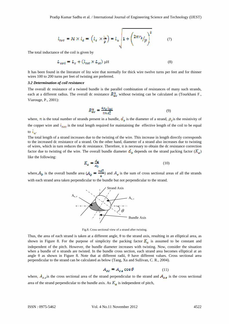
Fig.8. Cross sectional view of a strand after twisting.
Thus, the area of each strand is taken at a different angle, θ to the strand axis, resulting in an elliptical area, as shown in Figure 8. For the purpose of simplicity the packing factor is assumed to be constant and
independent of the pitch. However, the bundle diameter increases with twisting. Now, consider the situation when a bundle of n strands are twisted. In the bundle cross section, each strand area becomes elliptical at an angle θ as shown in Figure 8. Note that at different radii, θ have different values. Cross sectional area perpendicular to the strand can be calculated as below (Tang, Xu and Sullivan, C. R., 2004). (11)
where, is the cross sectional area of the strand perpendicular to the strand and is the cross sectional
area of the strand perpendicular to the bundle axis. As is independent of pitch,
Strand Axis
Bundle Axis
As, e As, c
Pradip Kumar Sadhu et al. / International Journal of Engineering Science and Technology (IJEST)
ISSN : 0975-5462 Vol. 4 No.11 November 2012 4522

(12)
where, is the overall bundle area when there is no twisting.
Therefore, the total cross sectional area of the strand perpendicular to each strand is calculated as follows:
, (13)
From the expression of total cross sectional area of the strand bundle diameter with twisting can be found as
(14)
Considering the d.c power loss in a twisted bundle the d.c resistance of the bundle can be found as
(15)
Including skin effect factor the a.c resistance of the coil is given by
(16)
3.3 Determination of On-Load Coil Parameters
In view of the e.m.f induced in the secondary metallic object with single turn due to the magnetic field produced by the heating coil (Pal. N., Sadhu P.K., Chakrabarti R.N., 2009) the total equivalent resistance and reactance of the object are given by
(17)
And (18)
Where ‘f’ is the switching frequency, µ is the permeability of the material, δ is depth of current penetration and N is the number of turns in the heating coil. The equivalent circuit of the induction heated system can be thought to consist of helical shaped heating coil as the primary winding of a transformer while the secondary metallic objects would behave as its closed secondary winding as shown in Fig.9. The resistance of the heating coil (Rcoil) changes with frequency due to skin and proximity effects and also due to the change in temperature. Lcoil is the self inductance of the heating coil. M represents the mutual inductance between heating coil and metallic objects. Reff is the effective resistance of the metallic object when referred to the heating coil side. The metallic object inductance referred to the heating coil side is L2 = M, as there is no physical winding on the metallic object side.
Fig.9. Equivalent circuit model for induction heater.
The heating coil and the heating object (load) can be represented by an equivalent series combination of Req and Leq, where the expressions of Req and Leq are as follows: (19)
Pradip Kumar Sadhu et al. / International Journal of Engineering Science and Technology (IJEST)
ISSN : 0975-5462 Vol. 4 No.11 November 2012 4523

(20)
Where (21)
For induction heating as the resistance (Reff) and the magnetizing reactance (M) of the secondary metallic object are of same magnitude, the equations (19) and (20) can be rewritten as:
(22)
(23)
3.4 Sample Calculations for Heating Coil Detailed calculations have been performed to calculate the on load value of coil inductance & a.c resistance for 24AWG strand size as this has been found suitable for industrial applications. Similar calculations can also be done for other strand sizes. In this context number of twists per feet has been taken as 100 and analysis is done at 33 kHz switching frequency as at this frequency resonance is found to occur.
Table 2. Dimensions of the twisted Litz coil for the physical set up
Physical parameters Layers, Strands (1,4) (2,7) (3,19) (4,37)
Radius of a strand, (m) 0.000255 0.000255 0.000255 0.000255 Number of helical turns, N 200 200 200 200
Coil radius of the helical coil, R(m) 0.04 0.04 0.04 0.04 Twisted bundle dia. Of the Litz wire,
(m) 0.00146 0.001951 0.004217 0.007487
Intermittent space between the winding of coil,
0.00146 0.001951 0.004217 0.007487
Packing factor ( ) 0.686413 0.777778 0.76 0.755102 Height of helical coil, H(m) 0.583951 0.780392 1.686864 2.994895
Total length of twisted helical coil, (m) 50.26601 50.26643 50.26989 50.27937 GMD of the coil, (m) 0.00044 0.000556 0.000968 0.00136
Table 3. Inductance of the multi-layered, helical shaped twisted litz coil
Layers, Strands (1,4) (2,7) (3,19) (4,37)
Inductance for strands per unit length of thecoil,
1.545933 1.499041 1.387962 1.320001
Total inductance of strands for the entire length
of coil=
77.70788 75.35142 69.7727 66.36883
Inductance for helical coil 406.4327 308.6366 146.2498 83.13337 The total inductance of the heating coil
H 484.1406 383.988 216.0225 149.5022
Table 4. AC resistance of the multi-layered, helical shaped twisted litz coil with skin effect
Layers, Strands (1,4) (2,7) (3,19) (4,37)
Untwisted d.c resistance Ω 1.05873 0.60499 0.222891 0.114457 Twisted d.c resistance, Ω 1.485429 0.98156 0.608274 0.502341
AC resistance with skin effect, Ω 1.802808 2.7060 4.267161 5.078483 Skin depth δ, m 0.000362 0.000362 0.000362 0.000362
AC resistance with skin effect & skin depth Ω 0.52216 0.390725 0.180773 0.101839
3.5 On-load Coil Parameters
When the high frequency induction heating system is loaded with some secondary metallic objects, the effective values of a.c resistance and inductance of litz wire are changed. The experiment has been conducted with different metallic objects.
Table 5. Physical parameters for secondary metallic objects
Pradip Kumar Sadhu et al. / International Journal of Engineering Science and Technology (IJEST)
ISSN : 0975-5462 Vol. 4 No.11 November 2012 4524

Physical parameters Secondary Metallic Object
Aluminum Copper Brass Galvanized Iron Stainless Steel
Relative Permeability 1 1
1.05
10
1
Permeability , 1.256 1.256 13.2 125.6 1.256 Resistivity, Ω-m,
2.75 1.7 6.39 9 72
With the physical parameters mentioned in Table 5 for different metals, equivalent inductance & a.c resistance for litz wire on load have been determined for 24 AWG strand size as presented in Table 6. This is because of the fact that for industrial applications the strand diameter of primary heating coil is kept as high as possible. Again for suitability in industrial applications 4-layered and 37-stranded heating coil is considered only.
Table 6. Equivalent resistance & inductance of litz wire at 33 kHz switching frequency
Secondary
Metallic Objects Equivalent Parameters of Heating Coil
Skin Depth, m
Effective, Resistance,
Ω
Effective Reactance,
Ω
Mutual Inductance, M,µH
Equivalent
Resistance, Ω
Equivalent
Inductance, µH
Equivalent Capacitance
for resonance,
, µF Aluminum 0.000457372 2.4050448 2.4050448 11.5 1.304361 143 0.159
Copper 0.000359607 1.8909554 1.8909554 9.03 1.047317 144 0.158 Brass 0.000680392 3.7566602 3.7566602 17.9 1.980169 140 0.163
Galvanized Iron 0.000261652 13.758721 13.758721 65.7 6.9812 116 0.197 Stainless Steel 0.002340289 12.306174 12.306174 58.8 6.254926 120 0.191
For industrial application of induction heated system, stainless steel is preferred as secondary metallic object and therefore, the equivalent coil inductance & a.c resistance have been used in later sections for analysis of hardware system of high frequency mirror inverter.
4. Hardware Prototype of the Present Scheme
The different photographs of the present experimental set-up are shown in Fig. 10 and Fig. 11.
Fig.10. Experimental set-up along with different measuring instruments.
Pradip Kumar Sadhu et al. / International Journal of Engineering Science and Technology (IJEST)
ISSN : 0975-5462 Vol. 4 No.11 November 2012 4525

Fig.11. Set-up for industrial medicinal plant.
Efficiency of experimental set-up by using single layer stainless steel (C12) package at different temperature set has been obtained. The developed prototype of induction heated system has been checked & verified with three phase input power supply. Water of 1.5kg is used as the fluid in this experimental work. All experimental data has been recorded with static water and water flows on both side of metallic object. With running water it would be difficult to sense the final steady state temperature of the water. Frequency is adjusted from 40 kHz 20 kHz with seven different temperature settings and efficiencies are calculated for each temperature setting as presented in Table 7.
Table 7. Efficiency of induction heater using mirror inverter at different operating frequency
SI.No. Temperature Setting
Switching Frequency (Hz)
Efficiency
01 Warm 40 70.2 02 Set-I 38 80.5 03 Set-II 33 94.3 04 Set-III 30 85.5 05 Set-IV 27 83.4 06 Set-V 23 79.6 07 Set-VI 20 72.7
Pradip Kumar Sadhu et al. / International Journal of Engineering Science and Technology (IJEST)
ISSN : 0975-5462 Vol. 4 No.11 November 2012 4526

The temperature response with respect to time is as shown in Table 8: Table 8. Temperature-time response at ‘Set-II’ position for three phase input
Sl No.
Time in (sec) Temperature (0C) Sl No. Time in (sec) Temperature (0C)
1 0 30.5 19 900 68.8 2 50 30.9 20 950 70.8 3 100 31.8 21 1000 72.6 4 150 32.3 22 1050 74.3 5 200 33.0 23 1100 75.9 6 250 34.7 24 1150 77.4 7 300 36.5 25 1200 78.6 8 350 38.5 26 1250 79.7 9 400 40.7 27 1300 80.7
10 450 43.0 28 1350 81.7 11 500 46.6 29 1400 82.5 12 550 49.4 30 1450 83.3 13 600 52.4 31 1500 83.9 14 650 55.5 32 1550 84.5 15 700 58.7 33 1600 85.0 16 750 61.6 34 1650 85.3 17 800 64.3 35 1700 85.5 18 850 66.8
Sample calculation corresponding to temperature setting –II for switching frequency of 33 kHz is presented here. Initial fluid temperature T1 =22.3 0C Final fluid temperature T2 =80.4 0C Initial fluid mass (water) m1=1.5kg Final fluid mass mf=1.332kg Mass of evaporated fluid = mev = mi –mf = 1.5-1.332 = 0.168 kg Time to reach final temperature = 631 sec Specific heat of fluid, Cp = 4186 J/kg-K Taking L = 2256900 J/kg, heat transferred to fluid PO = mJ CP (T2-T1) + mevL/ time in sec = 743969 J/631 sec=1179 W Input no load current = IO = 0.06 amp Input load current = IL = 1.84 amp Input voltage = VI = 436 volt Input power = PI = √3VI IL Cos , here Cos 0.9 = √3 X 436 X 1.84 X 0.9 = 1250.6W Efficiency of the system at temperature setting ‘Set-II’ =1179 / 1250.6 = 0.943 = 94.3%. Similarly the efficiency calculations for other temperature settings can also be performed. Detailed experimental results have been given in Table 9.
Table 9. Experimental results corresponding to different temperature settings for induction heated system
SI No.
Experimental quantities Warm Set-I Set-II Set-III Set-IV Set-V Set-VI
1 Input no load current 0.06 0.06 0.06 0.06 0.06 0.06 0.06 2 Input load current 0.183 0.267 0.496 0.80 1.31 1.81 2.35 3 Input voltage 440 440 440 440 440 440 440 4 Initial temperature of fluid 30.2 30.4 30.5 30.4 30.6 30.7 30.5 5 Final temperature of fluid 50.5 75.2 85.5 90.2 94.6 96.8 99.2 6 Initial mass of fluid 1.5 1.5 1.5 1.5 1.5 1.5 1.5 7 Final mass of fluid 1.5 1.488 1.412 1.376 1.346 1.324 1.302 8 Mass of evaporated fluid 0.0 0.012 0.088 0.124 0.154 0.176 0.198 9 Total time taken 1450 2100 1700 1350 1000 850 750
10 Heat power transferred to the fluid(Watt)
88 147.7 321.1 468.8 749.4 987.5 1170.9
11 Input power drawn from source(Watt)
125.5 183.2 340.2 548.7 898.5 1241.5 1611.8
12 Efficiency (%) 70.2 80.5 94.3 85.5 83.4 79.6 72.7
Pradip Kumar Sadhu et al. / International Journal of Engineering Science and Technology (IJEST)
ISSN : 0975-5462 Vol. 4 No.11 November 2012 4527
5. Construction of Secondary Metallic Object with Mirror Inverter
It is generally true that the more expensive the material is the more expensive is to construct the secondary metallic object for the induction heated system. The performance of the system depends not only upon the kind of metal but also upon the amount of metal used in the object. However, the other key factors that determine the cost of construction and the performance of the object are as under:
The conductivity of the metal. The thickness of the object walls. The surface area of the metallic object. The magnetic property of the metal used in the system. Layers of different metals used in the secondary side.
In view of the above lot of experiments have been carried out by choosing a secondary metallic object with single metallic sheet, double metallic sheet and triple metallic sheet. Different temperature sets were achieved for the proposed inverter circuit by changing the frequency of the gate drives to the semiconductor switches. The input currents and input voltages are recorded for each temperature set using three phase input.
5.1 Secondary Metallic Object with Single Metallic Sheet
Fig. 12 shows the structure of load for induction heated system using single metallic sheet. Experiments have been performed by choosing secondary metallic object with single metallic sheet made up of copper / brass / aluminum / stainless steel/galvanized iron. The experimental data are listed in Table 10 and the corresponding plot is presented in Fig.13. During the experiment input voltage remained at 440 volt (line to line).
Fig. 12 Structure of load for induction heater using single metallic sheet
Table10. Input current in amp for different temperature setting using different single layer metallic objects
Fig.13. Plot for input current-temperature set using different metals.
5.2 Secondary Metallic Object with Double Metallic Sheet Fig.14. shows the structure of load for induction heating using double metallic sheet. Experiments were performed by choosing metallic object with double metallic sheets out of which one is placed nearer to the heating coil called the down layer of the object and the other is placed away from the coil called up-layer of the object.
SI No. Metallic objects Warm Set-I Set-II Set-III Set-IV Set-V Set-VI 1 Copper 0.73 0.78 0.96 1.10 1.89 1.98 2.03 2 Brass 0.70 0.74 0.92 1.11 1.83 1.94 2.07 3 Aluminum 0.54 0.56 0.71 0.73 0.87 0.89 0.91 4 Stainless steel 1.59 1.64 1.84 2.03 4.11 4.23 4.32 5. Galvanized Iron 0.186 0.272 0.501 0.83 1.35 1.85 2.39
Pradip Kumar Sadhu et al. / International Journal of Engineering Science and Technology (IJEST)
ISSN : 0975-5462 Vol. 4 No.11 November 2012 4528

Fig.14. Structure of load for induction heater using double metallic sheet
The various combinations of the metals are aluminum-copper, aluminum-brass, copper-brass, stainless steel-brass, copper-galvanized iron etc. The experimental data for different combinations are obtained in similar way as for single layer metallic object and input current-temperature response for two different metals are also presented in Fig. 15.
(a) (b)
(c) (d)
(e)
Fig. 15. Input current variation of the induction heating-range at different temperature-set using double metallic sheet made heating vessel with (a) copper and aluminium, (b) brass and aluminium, (c) brass and copper, (d) brass and steel and (e) copper and galvanized iron (G.I) .
Pradip Kumar Sadhu et al. / International Journal of Engineering Science and Technology (IJEST)
ISSN : 0975-5462 Vol. 4 No.11 November 2012 4529

5.3 Secondary Metallic Object with Triple Metallic Sheet
Fig. 16 shows the structure of load for induction heater using triple metallic sheet. Experiments were performed by choosing secondary metallic objects with triple metallic sheets out of which one is placed nearer to the heating coil called the down layer of the object and the other is placed away from the coil called up-layer of the object and the third sheet is placed in between two layers called middle layer of the object.
Fig. 16. Structure of load for induction heater using triple metallic sheet .
The various combinations of the metals which have been tested are aluminum-copper- brass, aluminum-brass-steel etc. The experimental data for different combinations are obtained and plotted as shown in Fig. 17.
(a) (b)
Fig. 17. Input current variation of the induction heating-range at different temperature-set using triple metallic sheet made heating vessel with (a) aluminium, brass and copper and (b) aluminium, brass and steel .
6. Conclusion
In this paper first of all parameters of primary heating coil in on-load condition has been determined with different secondary metallic objects. For industrial application of induction heated system, stainless steel is preferred as secondary metallic object and therefore, the equivalent coil inductance & a.c resistance have been used in designing the litz wire . From the point of view to keep the strand diameter of the primary heating coil of the induction heater as high as possible for industrial applications, the strand size with 24 AWG is preferred.
Due to the inherent advantages, induction heated system based on high frequency mirror inverter are equally effective for industrial applications as it is for domestic equipments. To reduce the skin effect and proximity-effect losses, the heating coil is made of litz wire. However, choice of a litz wire construction is difficult and computation of a.c resistance, inductance of a litz wire is complex. In the present paper, an attempt is made to design a litz wire for industrial application. Inductance is calculated for four different litz wires, 1-layer-4-stranded, 2-layer-7-stranded, 3-layered-19-stranded and 4-layered-37-stranded.
From the study of a.c resistance determination, it has been noticed that number of twist results in less value of a.c resistance but at the same time inductance is reduced. However, keeping in mind the physical constraints of constructing a twisted litz wire, 100 numbers of twists per feet was considered. Moreover, a.c resistances were found to be increasing with the increase in operating frequency. Therefore, a lower value of operating frequency may be preferred.
Exhaustive experiments have been performed with high frequency mirror inverter & performance of the induction heated scheme has been verified using different secondary metallic objects. Using stainless steel as the metallic load and water as the fluid tests were conducted to compute the efficiency of the system by varying the switching frequency. It has been found that in the system temperature setting corresponding to Set-II provides the maximum efficiency at 33.33 kHz. For the mirror the inverter it has been observed that as the switching frequency falls with respect to the temperature setting ‘Warm’ up to ‘Set-II’, system efficiency rises and there
Pradip Kumar Sadhu et al. / International Journal of Engineering Science and Technology (IJEST)
ISSN : 0975-5462 Vol. 4 No.11 November 2012 4530

from with the frequency continue to fall efficiency also begins to fall with respect to the next temperature settings.
After performing real time experiments on the developed scheme it has been observed that the input current is maximum for stainless steel as compared to other conventionally used metals like brass, copper & aluminum. So it is better to employ a metallic sheet made of steel in induction heated systems. Experiments also show that the input current varies with the combination of metal plates of the secondary object and also upon the arrangement of these plates. It is seen that the current is maximum for a combined object having brass as upper plate and stainless steel as down plate as compared to other such double plate combinations of aluminum, brass, copper, stainless steel and G.I. sheet. Also the current does not significantly change by employing G.I. sheet as compared to that of stainless steel though the former gives slightly better response. In a similar way, experiments were carried out by employing triple layer of different metals. It is seen that the input current is maximum for the combined object having steel as down plate, brass as middle plate and aluminum as upper plate as compared to other such triple plate combinations of aluminum, brass, copper, and stainless steel. Therefore, on comparison of the test results it was concluded that the secondary object must be made from a material for which the product of resistivity and relative permeability is high enough to yield not only an acceptable efficiency but also higher input power and therefore stainless steel is the best possible choice as a metallic object in the induction heated system used in industrial appliances.
References
[1] Cheng, K. W. E. & Evans, P. D. (1994), “Calculation of winding losses in high frequency toroidal inductors using single strand conductors”, IEE Proc. of Power Electronic Applications, vol.141 no.2, pp.52-62.
[2] Dawson, F.P.; Jain, P (1991): “A comparison of Load commuted inverter systems for induction heating and melting applications” IEEE Trans. on Power Electronics Vol.6 no. 3, pp. 430 –441.
[3] Ferreira, J. A., (1994), “Improved analytical modeling of conductive losses in magnetic components”, IEEE Trans. Power Electronics, vol 9, pp.127-131.
[4] Pal. N., Sadhu P.K., Chakrabarti R.N., (2009), “Choice of Pan Material in Radio-frequency Mirror Inverter Induction Cooker”–Journal of Institution of Engineers (I);Vol 89, pp.09-18.
[5] Pal,N; Sadhu, P.K; and Chakrabarti,R.N (2006), “A Comparative Study of HF Mirror Inverter for Induction Cooker through Real-time and PSPICE Simulation” Journal of The Institution of Engineers, vol 86 , pp 268-274.
[6] Sadhu, P. K., Chakrabarti, R. N., Chowdhury, S. P., (2008), “A cooking apparatus using high frequency induction heating”, Patent Number 216361 dated 12/03/2008, Patent Office- Government of India
[7] Sadhu, P.K., Jana, N., Chakrabarti, R. N., Mitra, D. K. (2005), “A unique induction heated cooking appliances range using hybrid resonant converter”, World Scientific journal of circuits, systems and computers, vol. 14 no.3,pp.619-630.
[8] Sadhu, P. K., Mukherjee, S. K., Chakrabarti, R.N., Chowdhury, S. P., Karan, B. M. (2001), “A new generation microprocessor–based series resonant inverter for induction heated cooking appliances”, Journal of Indian Institution of Industrial Engineering, Navi Mumbai; Vol XXX ,no.9, pp.10-15.
[9] Sadhu, P. K., Chakrabarti, R. N., Chowdhury, S. P., (2001), “An improved inverter circuit arrangement”, Patent Number 69/cal/2001, Patent Office – Government of India.
[10] Sullivan, C. R., (1999), “Optimal choice for number of strands in a Litz-wire transformer winding”, IEEE transaction on Power Electronics, vol.14, no.2, pp.283–291.
[11] Tang, Xu and Sullivan, C. R., (2004), “Optimization of stranded-wire windings and comparison with Litz wire on the basis of cost and loss”, IEEE Power Electronics Specialists Conference, pp. 854 – 860.
[12] Tourkhani F., Viarouge, P., (2001), “Accurate Analytical Model of Winding Losses in Round Litz Wire Windings”, IEEE Transactions on Magnetics, vol.37, no.1, pp. 538-543.
[13] Wang ,S.P ; Nakaoka, M & Uchihoni,Y(1996) “New generation electromagnetic induction heated boiler & evaporator systems using power fector corrected series load resonant, PWM,IGBT inverter”- proceedings of PCIM 96, Europe pp. 719-726 .
[14] Wheeler, H. A. (1928), “Simple inductance formulas for radio coils”, Proc.of I.R.E., vol.16, no.10, pp. 1398-1400.
Pradip Kumar Sadhu et al. / International Journal of Engineering Science and Technology (IJEST)
ISSN : 0975-5462 Vol. 4 No.11 November 2012 4531


![Z SOURCE RESONANT CONVERTER FOR THE ELECTRIC VEHICLE ... · improve the efficiency over a wide input voltage and load variation[4]. Furthermore, a Z-source resonant converter (ZSRC)](https://img.dokumen.tips/doc/110x75/5d5ca46188c9931c5c8b4ef5/z-source-resonant-converter-for-the-electric-vehicle-improve-the-efficiency.jpg)