Embed Size (px)
Citation preview
Design of Fractal slot Antennas for WLAN and
WiMAX Applications
A Thesis submitted in partial fulfillment of the requirements for the degree of
Bachelor of Technology
In
Electronics and Instrumentation Engineering
By
JABLUN KERKETTA (108EI024)
And
SOUBHAGYA RANJAN BEHERA (108EI039)
DEPARTMENT OF ELECTRONICS AND COMMUNICATION ENGINEERING
NATIONAL INSTITUTE OF TECHNOLOGY
ROURKELA-769008 (ODISHA)
MAY-2012
Design of Fractal slot Antennas for WLAN and
WiMAX Applications
A Thesis submitted in partial fulfillment of the requirements for the degree of
Bachelor of Technology
In
Electronics and Instrumentation Engineering
By
JABLUN KERKETTA (108EI024)
And
SOUBHAGYA RANJAN BEHERA (108EI039)
Under the guidance of
Prof. S.K BEHERA
DEPARTMENT OF ELECTRONICS AND COMMUNICATION ENGINEERING
NATIONAL INSTITUTE OF TECHNOLOGY
ROURKELA-769008 (ODISHA)
MAY-2012

DEPARTMENT OF ELECTRONICS AND
COMMUNICATION ENGINEERING
NATIONAL INSTITUTE OF TECHNOLOGY, ROURKELA
ODISHA, INDIA-769008
CERTIFICATE
This is to certify that the thesis entitled “Design of Fractal slot Antenna for
WLAN and WiMAX Applications” was submitted by JABLUN
KERKETTA (108EI024) & SOUBHAGYA RANJAN BEHERA (108EI039)
in partial fulfillment of the requirements for the award of Bachelor of
Technology Degree in Electronics and Instrumentation Engineering during
session 2011-2012 at National Institute of Technology, Rourkela. A bonafide
record of research work carried out by them under my supervision and
guidance. The candidates have fulfilled all the prescribed requirements. The
thesis which is based on candidates’ own work, have not submitted elsewhere
for a degree or diploma. In my opinion, the thesis is of the standard required for
the award of a bachelor of technology degree in Electronics and Instrumentation
Engineering.
Place: Rourkela ( Prof. S.K Behera)

ii
ACKNOWLEDGEMENTS
On the submission of my thesis entitled “Design of Fractal slot Antennas for
WLAN and WiMAX Applications”, I would like to extend my gratitude &
my sincere thanks to my supervisor Prof. S.K Behera, Department of
Electronics and Communication Engineering, for his constant motivation and
support during the course of my work in the last one year. I truly appreciate and
value his esteemed guidance and encouragement from the beginning to the end
of this thesis. His knowledge and guidance at the time of crisis would be
remembered lifelong. I am very thankful to Sir Yogesh Choukiker for his
valuable suggestions and comments during this project period.
I am very thankful to my teachers for providing solid background for my studies
and research thereafter. At last but not least, I would like to thank the staffs of
Electronics and Communication Engineering Department for constant support
and providing place to work during the project period.
JABLUN KERKETTA
SOUBHAGYA RANJAN BEHERA
iii
ABSTRACT
A wideband printed slot antenna suitable for wireless local area network (WLAN) and
satisfying the worldwide interoperability for microwave access (WiMAX) applications is
proposed here. The antenna is microstrip line fed and its structure is based on fractal
geometry where the resonance frequency of antenna is lowered by applying iteration
techniques. The Project aims in finding the return loss and the radiation pattern. Analysis of
fractal antenna is done by using Software named CST Microwave Studio Suite. The antenna
size inclusive of the ground plane is compact and has a wide operating bandwidth. The
antenna exhibits omnidirectional direction radiation coverage with a gain better than 2.0 dBi
in the entire operating band. Fractals shapes and their properties are discussed. Hence it is
important to analyze them.

iv
CONTENTS
1. Introduction
1.1 Project background
1.2 Objectives
1.3 Scope of the project
1.4 Thesis Organization
2. Antenna theory
2.1 Introduction
2.2 Antenna properties
2.3 Basic Microstrip antenna
2.4 Feeding techniques
3. Fractal Antenna
3.1 Fractal theory
3.2 Fractal geometry
4. CPW fed Koch Fractal Slot Antenna
4.1 Theory
4.2 Design and Simulation
5. Sierpinski Carpet Antenna with CPW feed
5.1 Theory
5.2 Design and Simulation
6. Conclusion and future work
References

v
List of Figures and Tables
Figures
Figure Number Name of Figure Page Number
2.1 Parts of a Microstrip Antenna 16
2.2 Microstrip line feeding 17
2.3 Coaxial Probe feeding 18
2.4 Aperture couple feeding 19
2.5 Proximated couple feeding 19
3.1 Types of fractal geometries 22
3.2 Steps of construction for Gasket geometry 23
3.3 Steps of Iteration to get Carpet geometry 23
3.4 Steps of construction for Koch curve geometry 24
3.5 Steps for the Cantor Set geometry 24
4.1 1st 2
nd and 3
rd iteration
29
4.2 1
st iteration return loss
29
4.3 2nd
iteration return loss 30
4.4 Geometry of Koch Fractal Antenna 31
4.5 Different views of antenna 31
4.6 Return loss plot for Koch Antenna 32
4.7 Smith Chart plot for Koch Antenna
32
4.8 Far field plots for Koch Antenna 33
4.9 Gain plot for Koch Antenna 33
5.1 Gain plot for Antenna Design I
36

vi
5.2 Gain plot for Sierpinski carpet Antenna Design II
37
5.3 Gain plot for Sierpinski carpet Antenna Design III
37
5.4 Gain plot for Sierpinski carpet Antenna Design IV
37
5.5 Gain plot for Sierpinski carpet Antenna Design V
32
5.6 Gain plot for Sierpinski carpet Antenna Design VI
32
5.7 Gain plot for Sierpinski carpet Antenna Design VII
36
5.8 Gain plot for Sierpinski carpet Antenna Design VIII
36
5.9 Gain plot for Sierpinski carpet Antenna Design IX
39
5.10 Geometry of Sierpinski Carpet Antenna
39
5.11 Different views of antenna
40
5.12 Return Loss plot for Carpet Antenna
41
5.13 Smith Chart for Carpet Antenna
42
5.14 Farfield plot for antenna
42
5.15 Gain plot for Carpet Antenna
43
Tables
Table Number Name of Table Page Number
4.1 Dimensions for Koch Fractal Antenna Model 23
5.1 Dimensions for Sierpinski Carpet Antenna Model 29

1
CHAPTER 1
INTRODUCTION

2
1.1 PROJECT BACKGROUND
In modern wireless communication systems and increasing of other wireless applications,
wider bandwidth, multiband [7-8] and low profile antennas are in great demand for both
commercial and military applications. This has initiated antenna research in various
directions; one of them is using fractal shaped antenna elements. [9] Traditionally, each
antenna operates at a single or dual frequency bands[7-8], where different antenna is needed
for different applications. This will cause a limited space and place problem. In order to
overcome this problem, multiband antenna can be used where a single antenna can operate at
many frequency bands. One technique to construct a multiband antenna is by applying
fractal shape into antenna geometry [9]. This project presents the Koch and Sierpinski Gasket
patch antenna [3-4][10] where this famous shape, the antenna behaviors are investigated. In
addition to the theoretical design procedure, numerical simulation was performed using
software (CST) [11] to obtain design parameters such as size of patch and feeding location.
The antennas have been analyzed and designed by using the software CST Microwave Studio
Suite [11].
1.2 OBJECTIVE
The objective of this project is to design and simulate the Koch and Gasket patch (microstrip)
monopole fractal antenna [9-10]. The behavior and properties of these antennas are
investigated.
1.3 SCOPE OF THE PROJECT
The scopes defined for this project are as follows:
• Understanding the antenna concept.
• Perform numerical solutions using CST Microwave Studio software
• Study of the antenna properties.
• Comparison of measurement and simulation results.
3
1.4 THESIS ORGANIZATION
Chapter 1: In the first chapter basic overview of the project done is provided. This chapter
describes the need for microstrip antennas. Use of fractals in MA design is of a great use. A
brief history of the antenna is provided here.
Chapter 2: This chapter describes various antenna properties and terms associated with it.
Basic feeding techniques are well described. A small discussion is done on the advantages
and disadvantages of various types of feeding methods.
Chapter 3: This chapter describes how the use of fractal geometry in MA design had been of
a great use. Some efficient fractal geometries are described in this chapter.
Chapter 4: This chapter includes the design process and simulation results of Koch Fractal
Slot antenna with CPW (Coplanar waveguide) feed. The results showing various properties
of fractal antenna are also provided.
Chapter 5: This chapter includes the design process and simulation results of Sierpinski
Carpet antenna with CPW feed. The results showing various properties of fractal antenna are
also provided.
4
CHAPTER 2
ANTENNA THEORY
5
2.1 INTRODUCTION
Microstrip antenna [1-2] [12] is a simple antenna that consists of radiated patch component,
dielectric substrate, and ground plane. The radiated patch and ground plane is a thin layer of
copper or gold which is a good conductor. Each dielectric substrate has their own dielectric
permittivity values. This permittivity will influence the size of the Antenna. Microstrip
antenna is a low profile antenna. They have several advantages like light weight, small
dimension, cheap and easy to integrate with other circuits which make it chosen in many
applications.
2.2 ANTENNA PROPERTIES
The performance of the antenna is determined by several factors. Properties of those factors
are as follows:
Input Impedance
Generally, input impedance is important to determine maximum power transfer between
transmission line and the antenna. This transfer only happen when input impedance of
antenna and input impedance of the transmission line matches. If they do not match,
reflected wave will be generated at the antenna terminal and travel back towards the energy
source. This reflection of energy results causes a reduction in the overall system efficiency.
Gain
The gain of an antenna is essentially a measure of the antenna’s overall efficiency. If an
antenna is 100% efficient, it would have a gain equal to its directivity. There are many
factors that affect and reduce at the overall efficiency of an antenna. Some of the most
significant factors that impact antenna gain include impedance matching, network losses,
material losses and random losses. By considering all factors, it would appear that the
antenna must overcome a lot of adversity in order to achieve acceptable gain performance.

6
Radiation Pattern
The radiation patterns of an antenna provide the information that describes how the antenna
directs the energy it radiates. All antennas if 100% efficient, will radiate the same total
energy for equal input power regardless of the pattern shape. Radiation patterns are generally
presented on a relative power dB scale.
Directivity
Directivity, D is important parameter that shows the ability of the antenna focusing radiated
energy. Directivity is the ratio of maximum radiated to radiate reference antenna. Reference
antenna usually is an isotropic radiator where the radiated energy is same in all direction and
has directivity of 1. Directivity is defined as the following equation:
D = Fmax /F0
Where, Fmax = Maximum radiated energy
F0 = Isotropic radiator radiated energy
Polarization
The polarization of an antenna describes the orientation and sense of the radiated wave’s
electric field vector. There are three types of basic polarization:
• Linear polarization
• Elliptical polarization
• Circular polarization
Generally most antennas radiate with linear or circular polarization. Antennas with linear
polarization radiate at the same plane with the direction of the wave propagate. For circular
polarization the antenna radiate in circular form.
Bandwidth
The term bandwidth simply defines the frequency range over which an antenna meets a
certain set of specification performance criteria. The important issue to consider regarding
7
bandwidth is the performance tradeoffs between all of its performance properties described
above. There are two methods for computing an antenna bandwidth.
An antenna is considered broadband if fH/fL ≥ 2.
Narrowband by % age
BWp = (fh-fl)/f0 ×100%
Broadband by ratio
BWb= fh/fl
where f0 = Operating frequency
fh = Higher cut-off frequency
fl = Lower cut-off frequency
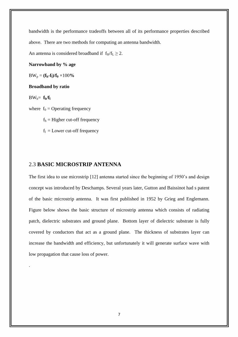
2.3 BASIC MICROSTRIP ANTENNA
The first idea to use microstrip [12] antenna started since the beginning of 1950’s and design
concept was introduced by Deschamps. Several years later, Gutton and Baissinot had s patent
of the basic microstrip antenna. It was first published in 1952 by Grieg and Englemann.
Figure below shows the basic structure of microstrip antenna which consists of radiating
patch, dielectric substrates and ground plane. Bottom layer of dielectric substrate is fully
covered by conductors that act as a ground plane. The thickness of substrates layer can
increase the bandwidth and efficiency, but unfortunately it will generate surface wave with
low propagation that cause loss of power.
.
8
Figure 2.1: Parts of a Microstrip Antenna
In the figure, h= substrates thickness; t= conductor thickness.
When a microstrip antenna is connected to a microwave source, it is energized. The charge
distribution will establish on the upper and lower surfaces of the patch, as well as on the
surface on the ground plane. The positive and negative charge distribution then arises.
Microstrip antennas have got high intention because of their good characteristics like:
• Low profile
• Light weight
• Cheap
• Easy to integrate with other circuits
• Used widely in many applications (both in commercial and military)
However there are several disadvantages of using microstrip antennas:
• Narrow bandwidth
• Low gain
• Surface wave excitation
• Low efficiency
• Low power handling capacity
9
2.4 FEEDING TECHNIQUES
Feeding techniques [1-2-13] are important in designing the antenna to make antenna structure
so that it can operate at full power of transmission. Designing the feeding techniques for high
frequency, need more difficult process. This is because the input loss of feeding increases
depending on frequency and finally give huge effect on overall design. There are a few
techniques that can be used.
1 Microstrip Line feeding
2 Coaxial Probe feeding
3 Aperture Coupled feeding
4 Proximate Coupled feeding
5 CPW feeding
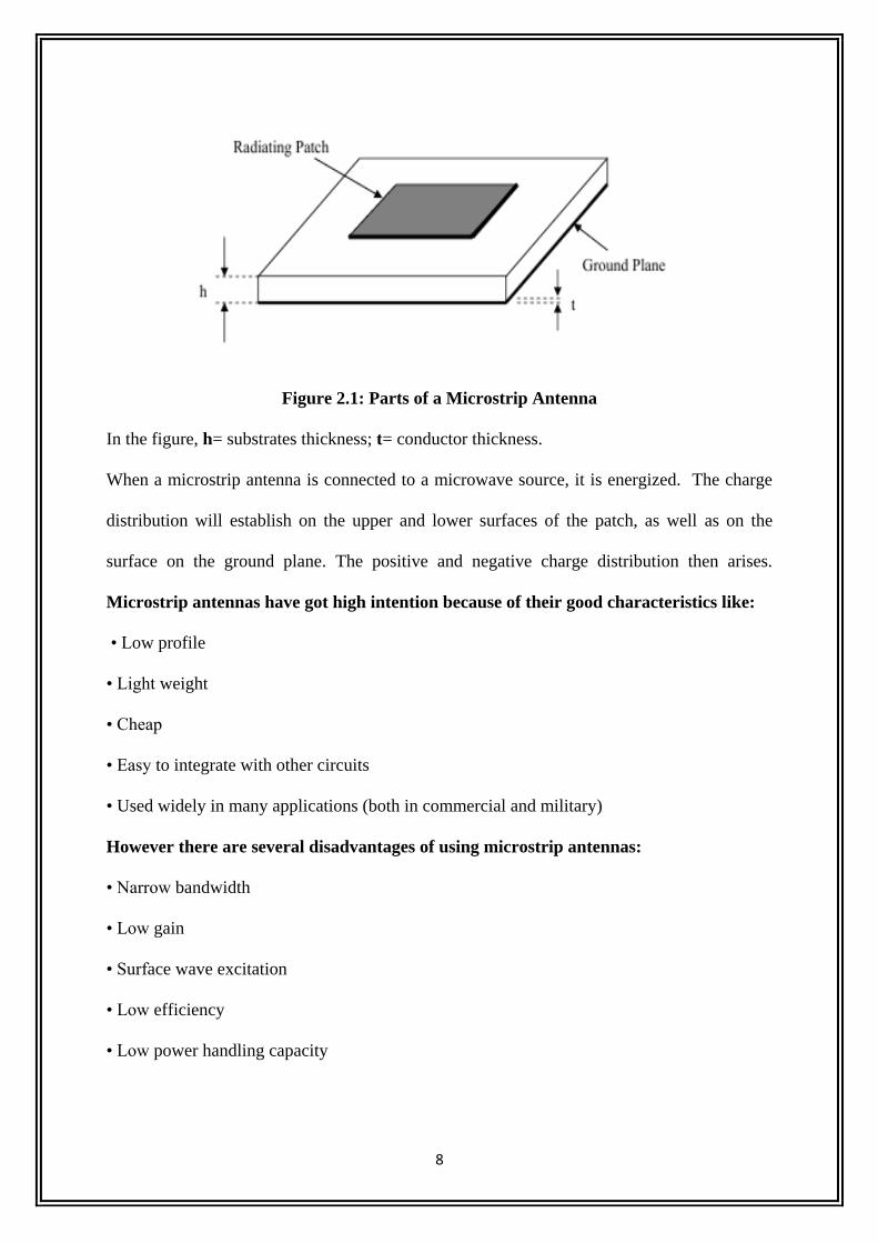
Microstrip Line feeding
It has more substrate thickness i.e. directly proprtional to the surface wave.
Radiation bandwidth limit is 2-5%.It is easy to fabricate and model. Microstrip line feed is
one of the easier methods to fabricate as it is a just conducting strip connecting to the patch
and therefore can be consider as extension of patch. It is simple to model and easy to match
by controlling the inset position. However the disadvantage of this method is that as substrate
thickness increases, surface wave and spurious feed radiation increases which limit the
bandwidth.
Figure 2.2: Microstrip line feeding
10
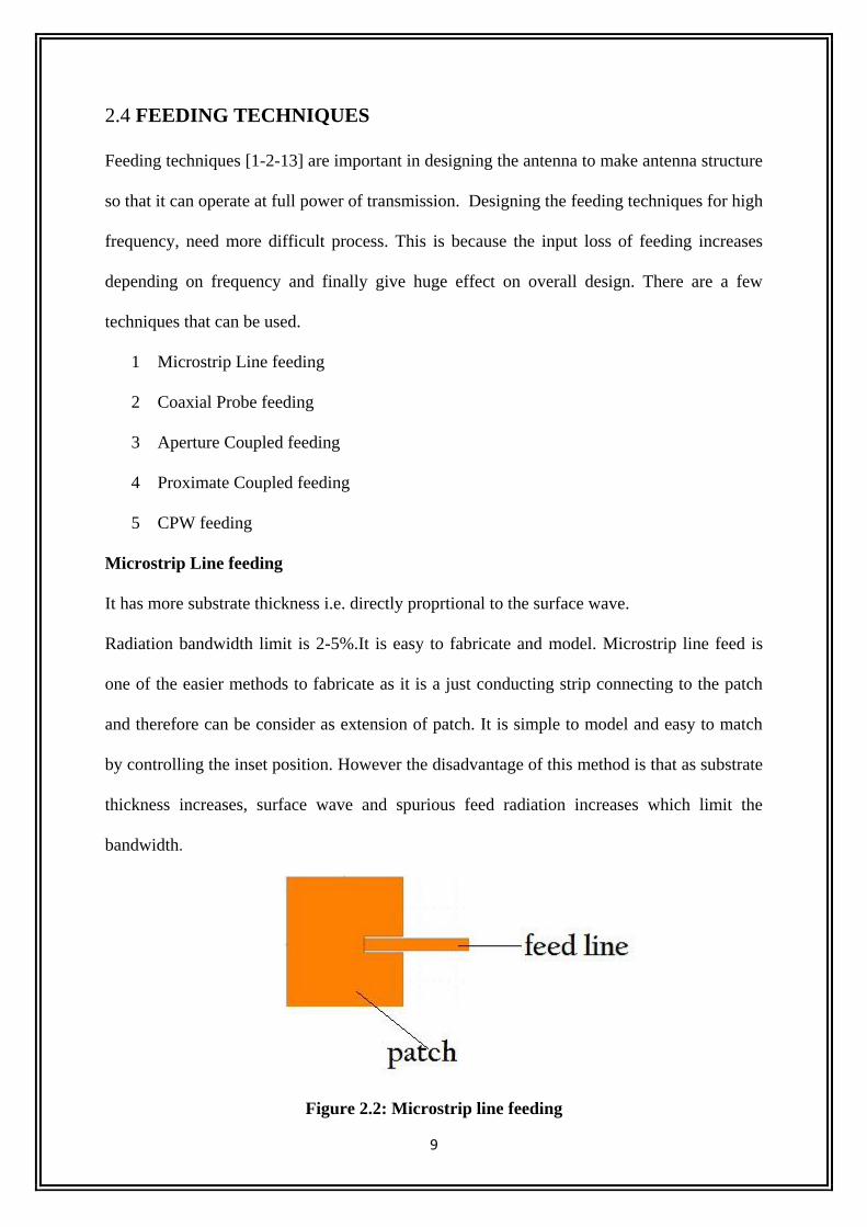
Coaxial Probe feeding
It has low spurious radiation and narrow bandwidth.It is easy to fabricate but difficult to
model. Coaxial feeding is feeding method in which that the inner conductor of the coaxial is
attached to the radiation patch of the antenna while the outer conductor is connected to the
ground plane.
Advantages
Easy of fabrication
Easy to match
Low spurious radiation
Disadvantages
Narrow bandwidth
Difficult to model specially for thick substrate
Possess inherent asymmetries which generate higher order modes which produce
cross-polarization radiation.
Figure 2.3: Coaxial Probe feeding
Aperture Coupled feeding
It has narrow bandwidth and moderate spurious radiation. Aperture coupling consist of two
different substrate separated by a ground plane. On the bottom side of lower substrate there is
a microstrip feed line whose energy is coupled to the patch through a slot on the ground plane
separating two substrates. This arrangement allows independent optimization of the feed
mechanism and the radiating element. Normally top substrate uses a thick low dielectric
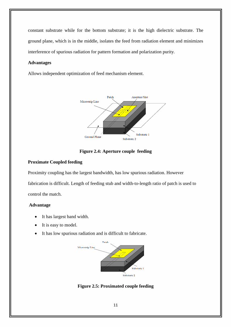
11
constant substrate while for the bottom substrate; it is the high dielectric substrate. The
ground plane, which is in the middle, isolates the feed from radiation element and minimizes
interference of spurious radiation for pattern formation and polarization purity.
Advantages
Allows independent optimization of feed mechanism element.
Figure 2.4: Aperture couple feeding
Proximate Coupled feeding
Proximity coupling has the largest bandwidth, has low spurious radiation. However
fabrication is difficult. Length of feeding stub and width-to-length ratio of patch is used to
control the match.
Advantage
It has largest band width.
It is easy to model.
It has low spurious radiation and is difficult to fabricate.
Figure 2.5: Proximated couple feeding
12
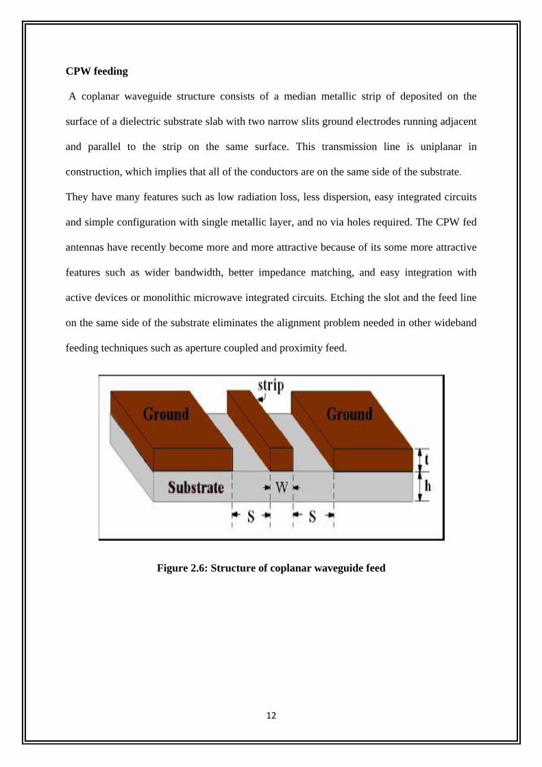
CPW feeding
A coplanar waveguide structure consists of a median metallic strip of deposited on the
surface of a dielectric substrate slab with two narrow slits ground electrodes running adjacent
and parallel to the strip on the same surface. This transmission line is uniplanar in
construction, which implies that all of the conductors are on the same side of the substrate.
They have many features such as low radiation loss, less dispersion, easy integrated circuits
and simple configuration with single metallic layer, and no via holes required. The CPW fed
antennas have recently become more and more attractive because of its some more attractive
features such as wider bandwidth, better impedance matching, and easy integration with
active devices or monolithic microwave integrated circuits. Etching the slot and the feed line
on the same side of the substrate eliminates the alignment problem needed in other wideband
feeding techniques such as aperture coupled and proximity feed.
Figure 2.6: Structure of coplanar waveguide feed
13
CHAPTER 3
FRACTAL ANTENNA
14
3.1 FRACTAL THEORY
In modern wireless communication systems wider bandwidth, multiband and low profile
antennas are in great demand for both commercial and military applications. This has
initiated antenna research in various directions; one of them is using fractal shaped antenna
elements. Traditionally, each antenna operates at a single or dual frequency bands, where
different antennas are needed for different applications.
Fractal shaped antennas have already been proved to have some unique characteristics that
are linked to the various geometry and properties of fractals. Fractals were first defined by
Benoit Mandelbrot in 1975 as a way of classifying structures whose dimensions were not
whole numbers. Fractal geometry has unique geometrical features occurring in nature. It can
be used to describe the branching of tree leaves and plants, rough terrain, jaggedness of
coastline, and many more examples in nature. Fractals have been applied in various field like
image compression, analysis of high altitude lightning phenomena, and rapid studies are
apply to creating new type of antennas.. Fractals are geometric forms that can be found in
nature, being obtained after millions of years of evolution, selection and optimization.
Fractal Antennas Elements
There are many benefits when we applied these fractals to develop various antenna elements.
By applying fractals to antenna elements:
• We can create smaller antenna size.
• Achieve resonance frequencies that are multiband.
• May be optimized for gain.
• Achieve wideband frequency band.
Most fractals have infinite complexity and detail that can be used to reduce antenna size and
develop low profile antennas. For most fractals, self-similarity concept can achieve multiple
frequency bands because of different parts of the antenna are similar to each other at different
15
scales. The combination of infinite complexity and self similarity makes it possible to design
antennas with various wideband performances.
We need fractal antenna due to the following facts:
Very broadband and multiband frequency response that derives from the inherent
properties of the fractal geometry of the antenna.
Compact size compared to antennas of conventional designs, while maintaining good
to excellent efficiencies and gains.
Mechanical simplicity and robustness; the characteristics of the fractal antenna are
obtained due to its geometry and not by the addition of discrete components.
Design to particular multi frequency characteristics containing specified stop bands as
well as specific multiple pass bands.
3.2 FRACTAL GEOMETRY.
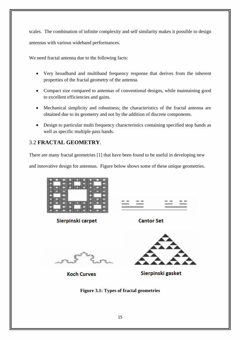
There are many fractal geometries [1] that have been found to be useful in developing new
and innovative design for antennas. Figure below shows some of these unique geometries.
Figure 3.1: Types of fractal geometries
16
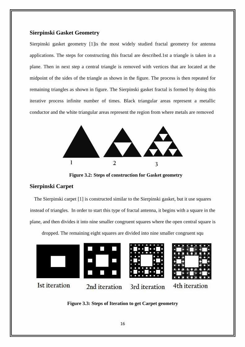
Sierpinski Gasket Geometry
Sierpinski gasket geometry [1]is the most widely studied fractal geometry for antenna
applications. The steps for constructing this fractal are described.1st a triangle is taken in a
plane. Then in next step a central triangle is removed with vertices that are located at the
midpoint of the sides of the triangle as shown in the figure. The process is then repeated for
remaining triangles as shown in figure. The Sierpinski gasket fractal is formed by doing this
iterative process infinite number of times. Black triangular areas represent a metallic
conductor and the white triangular areas represent the region from where metals are removed
Figure 3.2: Steps of construction for Gasket geometry
Sierpinski Carpet
The Sierpinski carpet [1] is constructed similar to the Sierpinski gasket, but it use squares
instead of triangles. In order to start this type of fractal antenna, it begins with a square in the
plane, and then divides it into nine smaller congruent squares where the open central square is
dropped. The remaining eight squares are divided into nine smaller congruent squ
Figure 3.3: Steps of Iteration to get Carpet geometry
17
Koch Curves
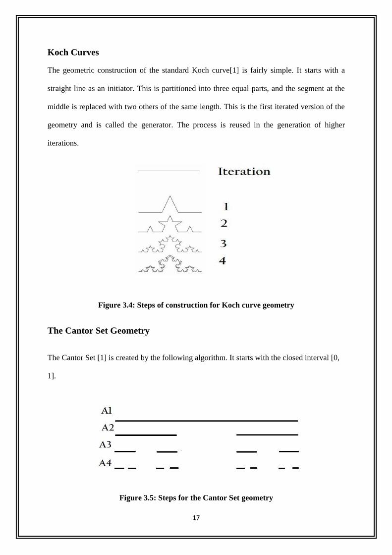
The geometric construction of the standard Koch curve[1] is fairly simple. It starts with a
straight line as an initiator. This is partitioned into three equal parts, and the segment at the
middle is replaced with two others of the same length. This is the first iterated version of the
geometry and is called the generator. The process is reused in the generation of higher
iterations.
Figure 3.4: Steps of construction for Koch curve geometry
The Cantor Set Geometry
The Cantor Set [1] is created by the following algorithm. It starts with the closed interval [0,
1].
Figure 3.5: Steps for the Cantor Set geometry

18
Say it as set A1 or the 0th (initial) set. Delete the middle open third. This leaves a new set,
called A2 [0,1/3] U [2/3,1]. Each iteration through the algorithm removes the open middle
third from each segment of the previous iteration. Thus, the next two sets would be A3[0,1/9
]U[2/9,1/3]U[2/3,7/9]U[8/9,1] and according to the previous one A4 set will be A4
[0,1/27]U[2/27,1/9]U[2/9,7/27]U
[8/27,1/3]U[2/3,19/27]U[20/27,7/9]U[8/9,25/27]U[26/27,1]. We can see that the set becomes
sparser as the number of iteration increases. The Cantor Set is defined to be the set of the
points that remain as the number of iterations tends to infinity.
19
CHAPTER 4
CPW-FED KOCH FRACTAL SLOT ANTENNA
20
4.1 THEORY
Since there is a rapid development in wireless communication systems their applications are
increasing every day. The ultra wideband antenna has become an important factor in
developing the Ultra wideband technique. Accordingly antennas are designed to radiate in a
relatively narrow range of frequencies. As opposed to traditional narrowband antennas, the
UWB antennas can transmit and receive electromagnetic waves in a wide range. The Ultra
wide antennas are used to transmit the signal with minimum noise and distortion in the shape
of the pulses. Much important is that the increasing demand for low profile and portable
miniature wireless systems has increased interests in the compact antennas .As an significant
member of the Ultra wideband family, the slot antenna has the advantages of wideband, and
the cost is low benefits are there. It can be integrated with many electronics devices, chips,
mobile phones etc. There are more advantages of low radiation loss, and dispersion. The
structure of coplanar-waveguide- (CPW-) fed printed slot antennas is very simple consisting
of a single metallic layer. It can be easily integrated with microwave integrated circuits.
In this CPW-fed slot antenna the bandwidth is increased. Koch fractal geometry is applied in
this antenna. WLANs (Wireless Local Area Networks) are proposed to operate in the 2.4
GHz frequency bands (2.4 - 2.48 GHz) and 5 GHz frequency bands (5.15–5.35 GHz).
WiMAX (Worldwide Interoperability for Microwave Access) is designed to operate in the
range 2.5 - 2.69/3.4 - 3.69/5.25 - 5.85 GHz bands. Since this range of frequencies can be
used simultaneously in many systems, we need a single antenna that covers all these ranges.
The minimum resonance of the wide slot antenna depends on the slot boundary .The concept
of space filling of the Koch curves used in the design of miniature and multi-band patch
antennas can also be applied for wide-slot antennas.
Here we use a CPW-fed modified Koch Snowflake slot antenna operating over a wide
frequency band, covering the 2.4/5.2/5.8 GHz range for WLAN and 2.5/3.5/4.5 GHz range

21
for WiMAX . The definitions for some terms used to describe the simulated result are
provided below.
S-Parameter
S-parameters describe the input-output relationship between terminals (or ports) in a
circuit system.
It represents the power reflected or radiated by the antenna.
It is a measure of the accepted power by the antenna.
Smith Chart
The Smith Chart is used for visualizing the impedance of a transmission line and antenna
system as a function of frequency.
It is extremely helpful for impedance matching.
Smith Chart is a graphical method of displaying the impedance of an antenna, which can
be a single point or a range of points to display the impedance as a function of frequency.
Far field
Far field determines antenna's radiation pattern.
The far field is the region far from the antenna where the radiation pattern does not
change shape with distance.
This region is dominated by radiated fields, with the E- and H-fields orthogonal to each
other.
22
Gain
Antenna Gain describes the amount of power transmitted in the direction of peak
radiation to that of an isotropic source.
Antenna gain accounts for the actual losses that occur.
4.2 PROPOSED ANTENNA DESIGN
The proposed model is designed using three iterative steps. Here the same radiating patch is
used throughout the steps. But, the ground plane shape is modified in the consecutive steps.
Starting from a triangle and superimposing another similar inverted triangle upon it and so on
we have obtained the required geometry.
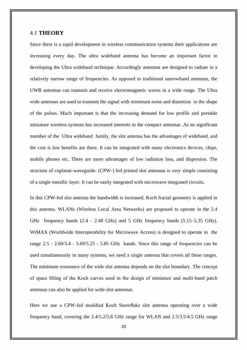
Koch Snowflake geometry in its different iteration stages are depicted below.
Fig 4.1 1st 2nd
and 3rd
iteration
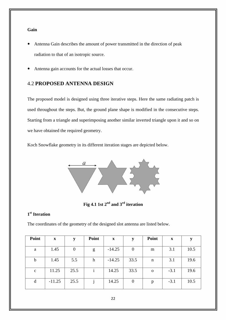
1st Iteration
The coordinates of the geometry of the designed slot antenna are listed below.
Point x y Point x y Point x y
a 1.45 0 g -14.25 0 m 3.1 10.5
b 1.45 5.5 h -14.25 33.5 n 3.1 19.6
c 11.25 25.5 i 14.25 33.5 o -3.1 19.6
d -11.25 25.5 j 14.25 0 p -3.1 10.5
23
e -1.45 5.5 k 1.1 0 q -1.1 8
f -1.45 0 l 1.1 8 r -1.1 8
According to the given table the various parts of the antenna were designed and the model
was simulated. The pictorial representation of designed model and the return loss from the
simulated results are given below.
Geometry
Fig 4.2 1st iteration return loss
24
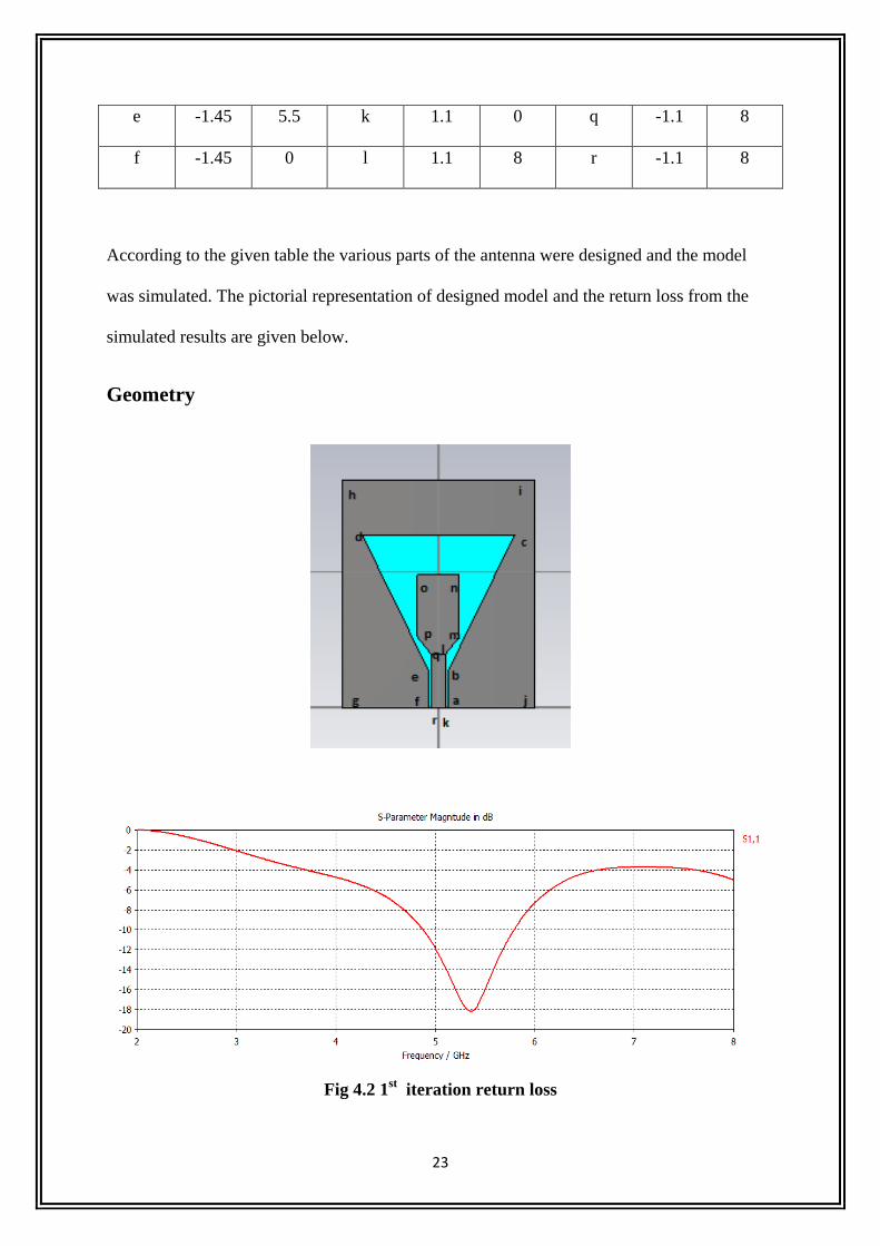
2nd
Iteration
The coordinates of the geometry of the designed slot antenna are listed below.
Point x y Point x y Point x y
a 1.45 0 f 11.25 25.5 k -7.5 18
b 1.45 5.5 g 3.75 25.5 l -11.25 10.5
c 3.75 10.5 h 0 33 m -3.75 10.5
d 11.25 10.5 i -3.75 25.5 n -1.45 5.5
e 7.5 18 j -11.25 25.5 o 1.45 0
According to the given table the various parts of the antenna were designed and the model
was simulated. The pictorial representation of designed model and the return loss from the
simulated results are given below
Geometry
25
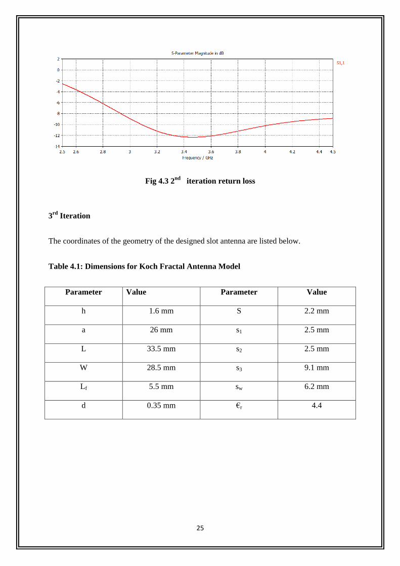
Fig 4.3 2nd
iteration return loss
3rd
Iteration
The coordinates of the geometry of the designed slot antenna are listed below.
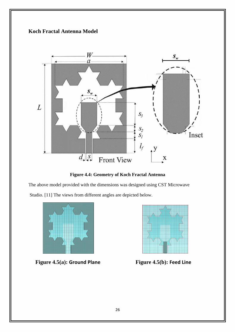
Table 4.1: Dimensions for Koch Fractal Antenna Model
Parameter Value Parameter Value
h 1.6 mm S 2.2 mm
a 26 mm s1 2.5 mm
L 33.5 mm s2 2.5 mm
W 28.5 mm s3 9.1 mm
Lf 5.5 mm sw 6.2 mm
d 0.35 mm €r 4.4
26
Koch Fractal Antenna Model
Figure 4.4: Geometry of Koch Fractal Antenna
The above model provided with the dimensions was designed using CST Microwave
Studio. [11] The views from different angles are depicted below.
Figure 4.5(a): Ground Plane Figure 4.5(b): Feed Line
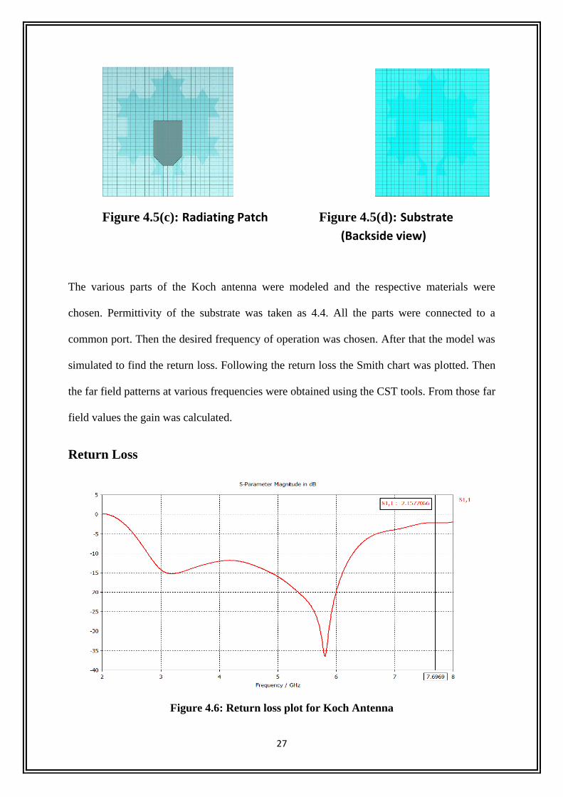
27
Figure 4.5(c): Radiating Patch Figure 4.5(d): Substrate
(Backside view)
The various parts of the Koch antenna were modeled and the respective materials were
chosen. Permittivity of the substrate was taken as 4.4. All the parts were connected to a
common port. Then the desired frequency of operation was chosen. After that the model was
simulated to find the return loss. Following the return loss the Smith chart was plotted. Then
the far field patterns at various frequencies were obtained using the CST tools. From those far
field values the gain was calculated.
Return Loss
Figure 4.6: Return loss plot for Koch Antenna
28
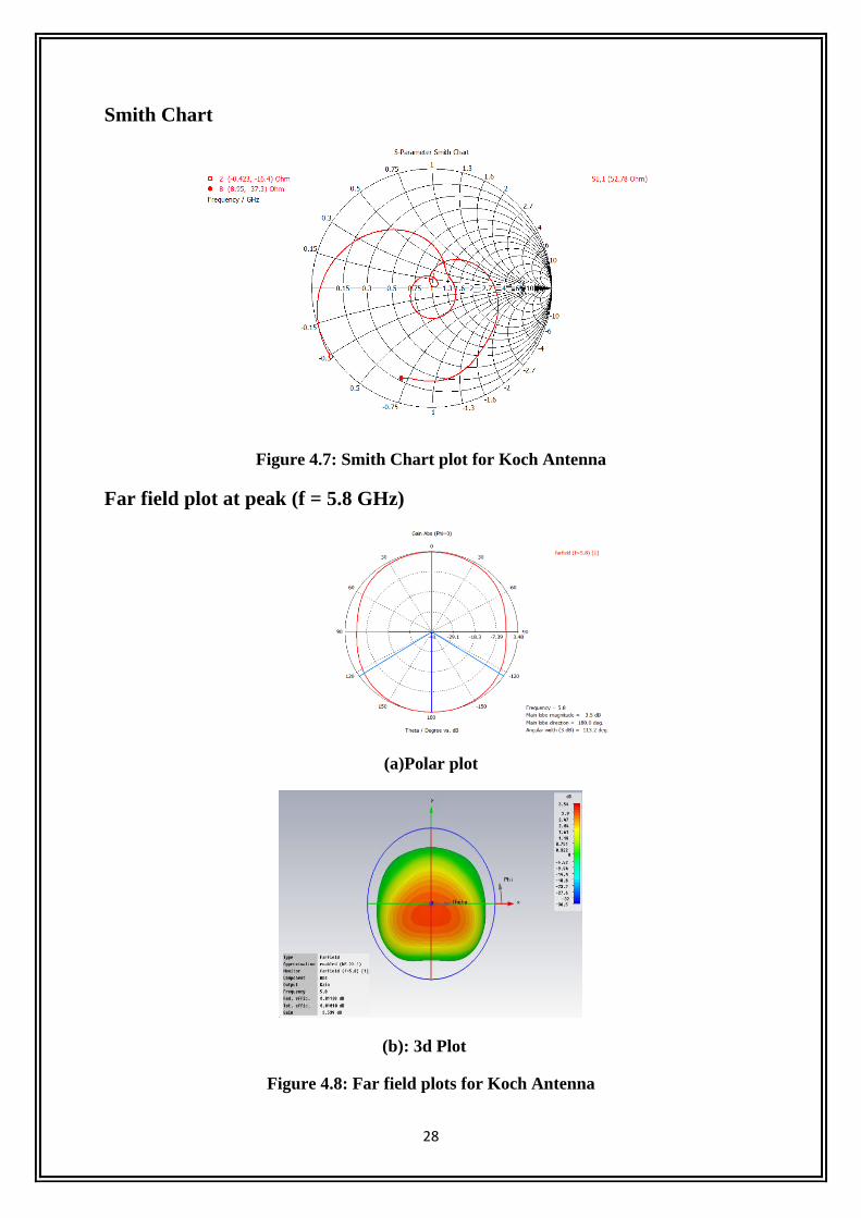
Smith Chart
Figure 4.7: Smith Chart plot for Koch Antenna
Far field plot at peak (f = 5.8 GHz)
(a)Polar plot
(b): 3d Plot
Figure 4.8: Far field plots for Koch Antenna
29
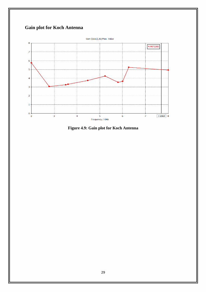
Gain plot for Koch Antenna
Figure 4.9: Gain plot for Koch Antenna
30
CHAPTER 5
SIERPINSKI CARPET ANTENNA WITH CPW FEED
31
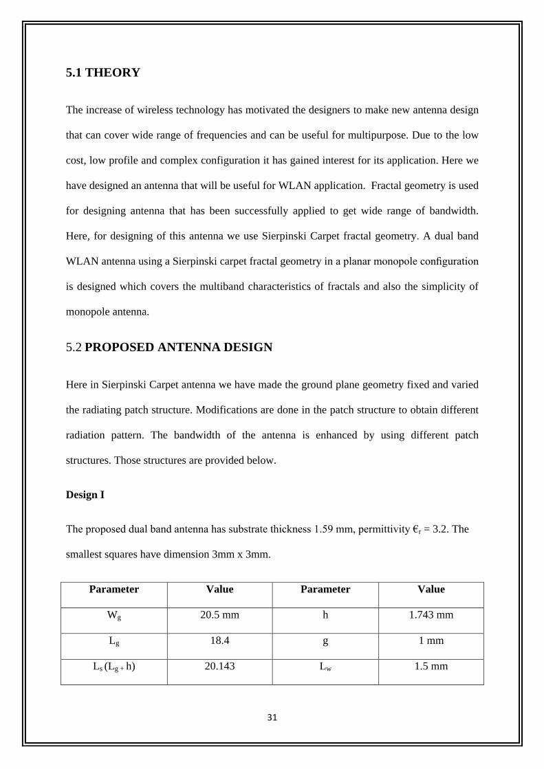
5.1 THEORY
The increase of wireless technology has motivated the designers to make new antenna design
that can cover wide range of frequencies and can be useful for multipurpose. Due to the low
cost, low profile and complex configuration it has gained interest for its application. Here we
have designed an antenna that will be useful for WLAN application. Fractal geometry is used
for designing antenna that has been successfully applied to get wide range of bandwidth.
Here, for designing of this antenna we use Sierpinski Carpet fractal geometry. A dual band
WLAN antenna using a Sierpinski carpet fractal geometry in a planar monopole configuration
is designed which covers the multiband characteristics of fractals and also the simplicity of
monopole antenna.
5.2 PROPOSED ANTENNA DESIGN
Here in Sierpinski Carpet antenna we have made the ground plane geometry fixed and varied
the radiating patch structure. Modifications are done in the patch structure to obtain different
radiation pattern. The bandwidth of the antenna is enhanced by using different patch
structures. Those structures are provided below.
Design I
The proposed dual band antenna has substrate thickness 1.59 mm, permittivity €r = 3.2. The
smallest squares have dimension 3mm x 3mm.
Parameter Value Parameter Value
Wg 20.5 mm h 1.743 mm
Lg 18.4 g 1 mm
Ls (Lg + h) 20.143 Lw 1.5 mm
32
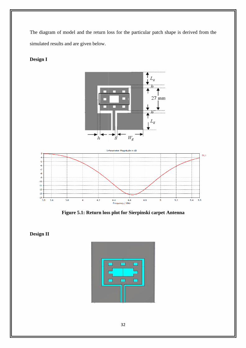
The diagram of model and the return loss for the particular patch shape is derived from the
simulated results and are given below.
Design I
Figure 5.1: Return loss plot for Sierpinski carpet Antenna
Design II
33
Figure 5.2: Return loss plot for Sierpinski carpet Antenna
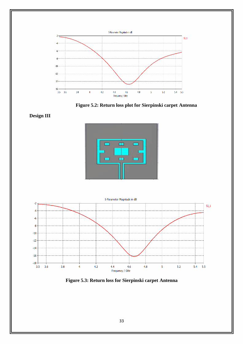
Design III
Figure 5.3: Return loss for Sierpinski carpet Antenna
34
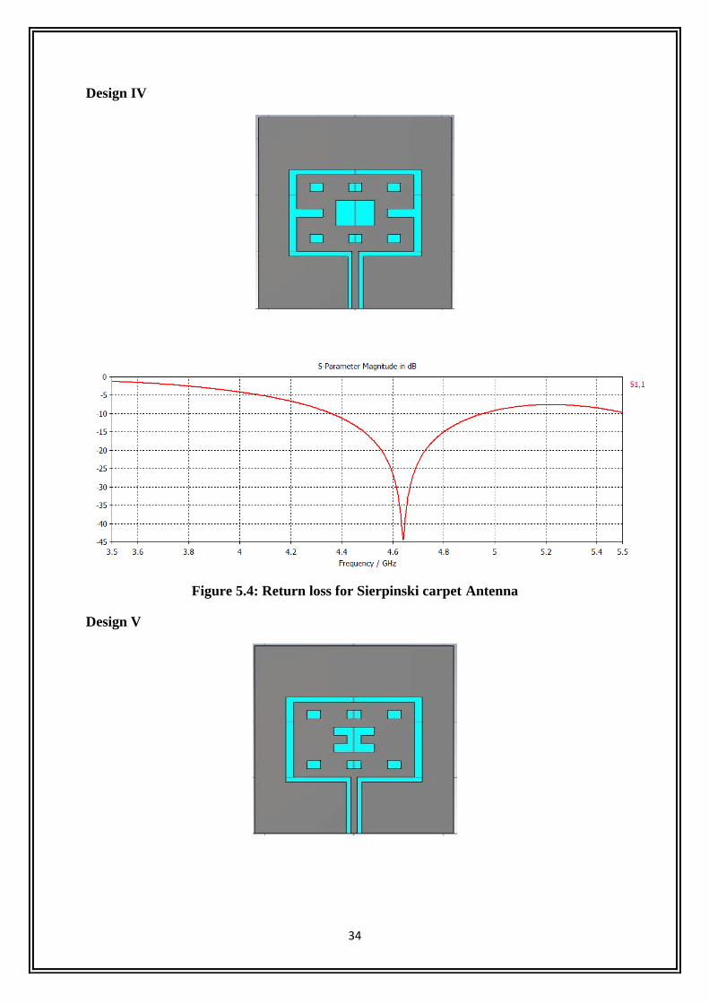
Design IV
Figure 5.4: Return loss for Sierpinski carpet Antenna
Design V
35
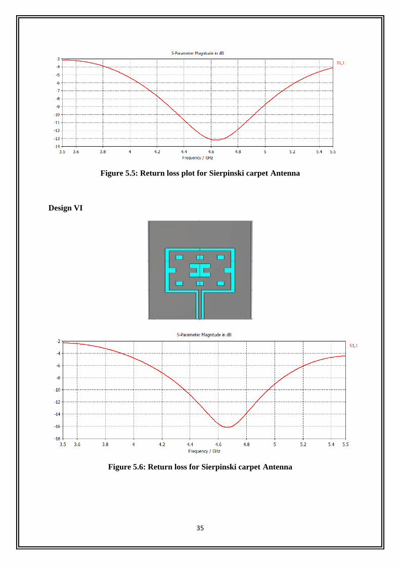
Figure 5.5: Return loss plot for Sierpinski carpet Antenna
Design VI
Figure 5.6: Return loss for Sierpinski carpet Antenna
36
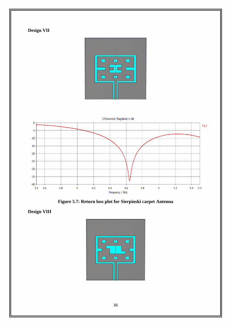
Design VII
Figure 5.7: Return loss plot for Sierpinski carpet Antenna
Design VIII
37
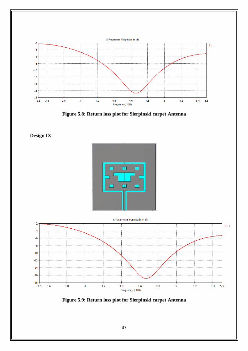
Figure 5.8: Return loss plot for Sierpinski carpet Antenna
Design IX
Figure 5.9: Return loss plot for Sierpinski carpet Antenna
38
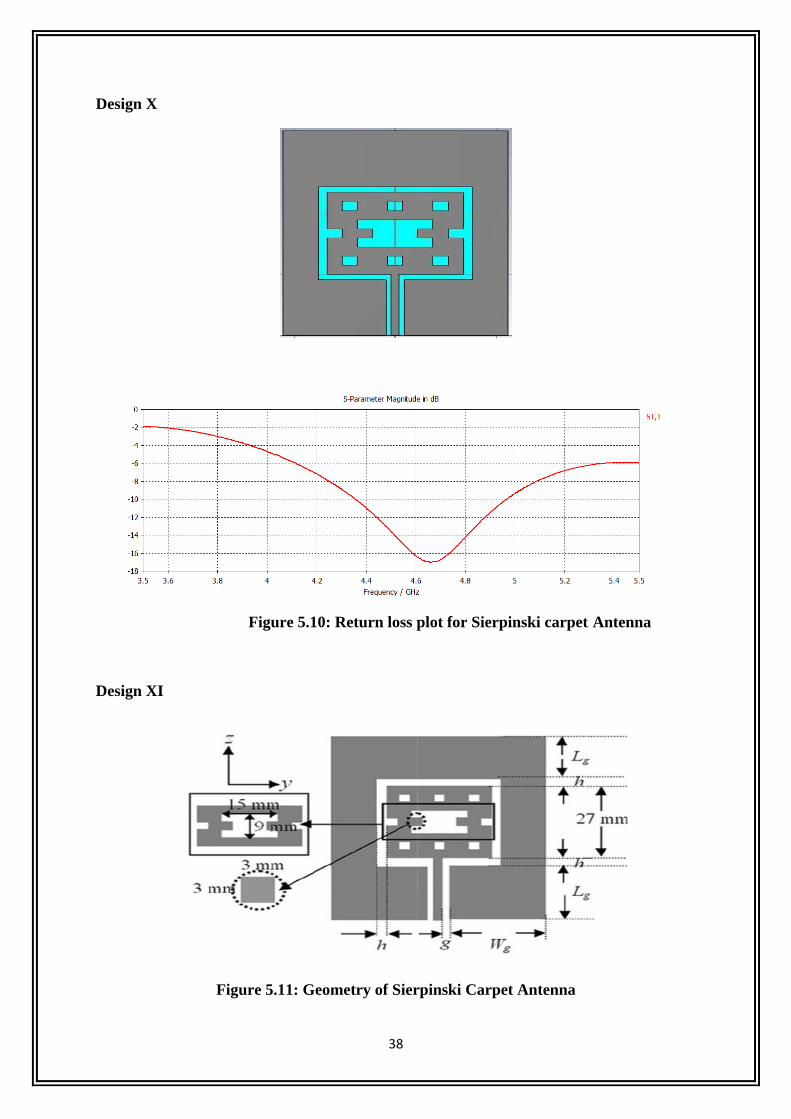
Design X
Figure 5.10: Return loss plot for Sierpinski carpet Antenna
Design XI
Figure 5.11: Geometry of Sierpinski Carpet Antenna
39
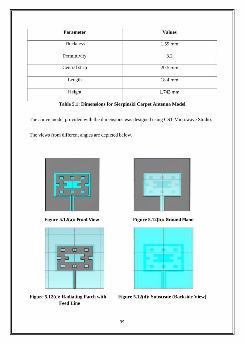
Parameter Values
Thickness 1.59 mm
Permittivity 3.2
Central strip 20.5 mm
Length 18.4 mm
Height 1.743 mm
Table 5.1: Dimensions for Sierpinski Carpet Antenna Model
The above model provided with the dimensions was designed using CST Microwave Studio.
The views from different angles are depicted below.
Figure 5.12(a): Front View Figure 5.12(b): Ground Plane
Figure 5.12(c): Radiating Patch with Figure 5.12(d): Substrate (Backside View)
Feed Line
40
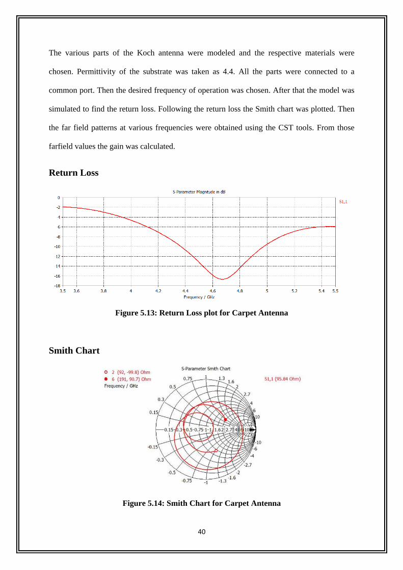
The various parts of the Koch antenna were modeled and the respective materials were
chosen. Permittivity of the substrate was taken as 4.4. All the parts were connected to a
common port. Then the desired frequency of operation was chosen. After that the model was
simulated to find the return loss. Following the return loss the Smith chart was plotted. Then
the far field patterns at various frequencies were obtained using the CST tools. From those
farfield values the gain was calculated.
Return Loss
Figure 5.13: Return Loss plot for Carpet Antenna
Smith Chart
Figure 5.14: Smith Chart for Carpet Antenna
41
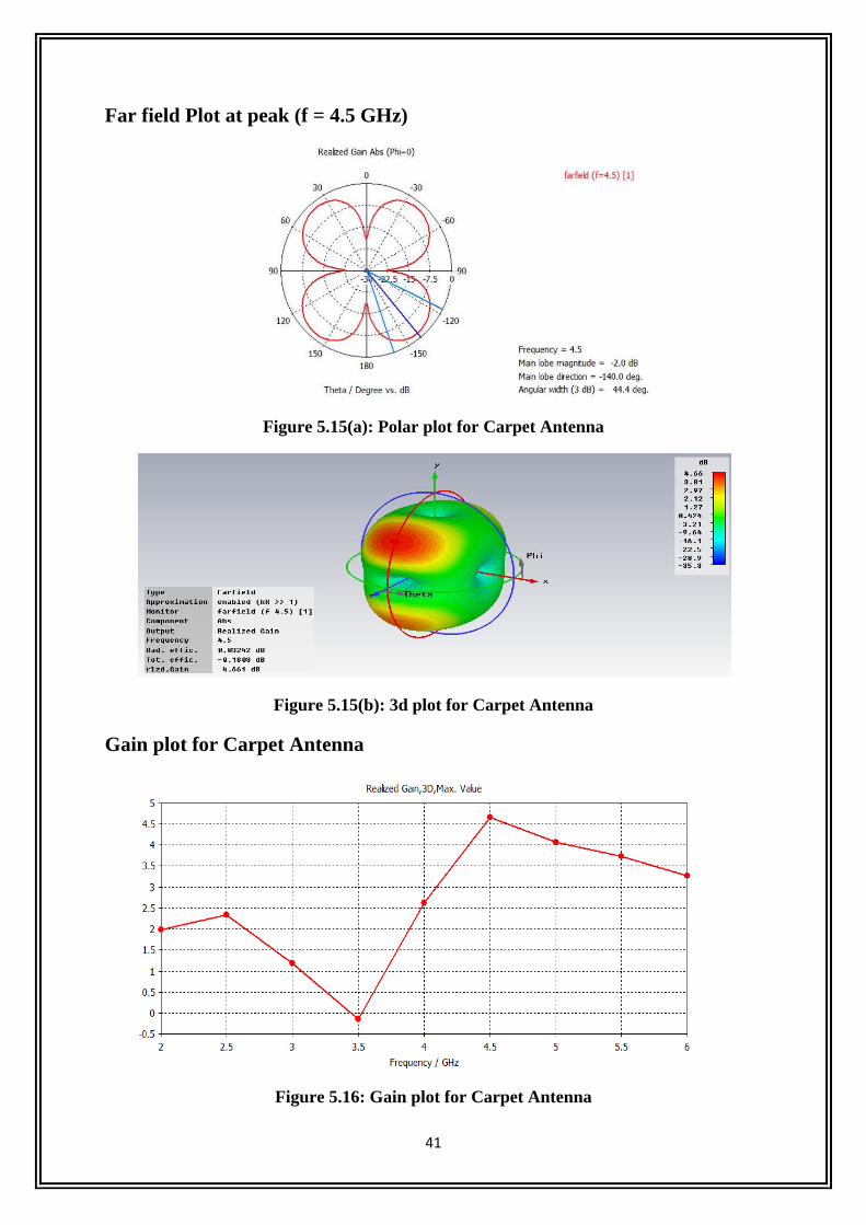
Far field Plot at peak (f = 4.5 GHz)
Figure 5.15(a): Polar plot for Carpet Antenna
Figure 5.15(b): 3d plot for Carpet Antenna
Gain plot for Carpet Antenna
Figure 5.16: Gain plot for Carpet Antenna

42
CHAPTER 6
CONCLUSION AND FUTURE WORK
43
CONCLUSION
CPW-fed Koch fractal printed slot antenna is suitable for WLAN 2.4/5.2/5.5 GHz and
WiMAX 2.5/3.5/5.5 GHz operations. This geometry lowers the frequency of operation
along with wide band matching and antenna size is compact as well as simple.
Perturbed Sierpinski carpet fractal antenna with CPW feed is suitable for WLAN
applications. The overall size can be effectively utilized for integrating with other
components in WLAN communication devices.
FUTURE WORK
The proposed antenna will be fabricated and measured result will be compared with
simulated results.
After fabrication it will be operated in the given conditions and the radiation pattern will
be analyzed.
The errors will be minimized by using given tools.
44
REFERENCES
[1]. Vinoy, K. J., “Fractal shaped antenna elements for wide and multi-band wireless
applications,” Thesis, Pennsylvania, Aug. 2002.
[2]. Constantine A. Balanis, Antenna Theory Analysis & Design, John Wiley & Sons,
1997
[3]. Deepti Das Krishna, Student Member, IEEE, M. Gopikrishna, Student Member,
IEEE, C. K. Anandan,, P. Mohanan, Senior Member, IEEE, and K. Vasudevan,
Senior Member, IEEE, "CPW-Fed Koch Fractal Slot Antenna for WLAN/WiMAX
Applications", IEEE ANTENNAS AND WIRELESS PROPAGATION LETTERS,
VOL. 7, 2008
[4]. Ghatak, R.; Mishra, R.K.; Poddar, D.R.; , "Perturbed Sierpinski Carpet Antenna With
CPW Feed for IEEE 802.11 a/b WLAN Application," Antennas and Wireless
Propagation Letters, IEEE , vol.7, no., pp.742-744, 2008
[5]. S. S. Zhong and X. L. Liang, “Progress in ultra-wideband planar antennas,” Journal of
Shanghai University, vol. 11, no.2, pp. 95–101, 2007
[6]. C. Y. Huang and D. Y. Lin, “CPW-fed bow-tie slot antenna for ultra-wideband
communications,” Electronics Letters, vol. 42,no. 19, pp. 1073–1074, 2006
[7]. D. D. Krishna, M. Gopikrishna, C. K. Aanandan, P. Mohanan,and K. Vasudevan,
“Compact wideband Koch fractal printed slot antenna,” IET Microwaves, Antennas
and Propagation, vol3, no. 5, pp. 782–789, 2009.
[8]. B.-L. Ooi, “A modified contour integral analysis for Sierpinski fractal carpet
antennas with and without electromagnetic band gap groundplane,” IEEE Trans.
Antennas Propag., vol. 52, pp. 1286–1293, May2004.

45
[9]. Introduction to antenna and near-field simulation in CSTMicrowave Studio®
software By Jorge R. Costa Jerzy Guterman
[10]. E. S. Angelopoulos, A. Z. Anastopoulos, D. I. Kaklamani, A. A.Alexandridis, F.
Lazarakis, and K. Dangakis, “Circular and elliptical CPW-Fed slot and microstrip-fed
antennas for ultrawide-band applications,” IEEE Antennas Wireless Propag. Lett.,
vol. 5, pp. 294–297,2006.
[11]. J. Gutrman, A. A. Moreira, and C. Peixeiro, “Microstrip fractal antennas for
multistandard terminals,” IEEE Antennas Wireless Propag.Lett., vol. 3, pp. 351–2004


![SULIT 2 3767/2 Bahagian A semua soalan daripada bahagian ini · SULIT 2 3767/2 3767/2@2019 Hak Cipta MPSM Kelantan SULIT [LIHAT HALAMAN SEBELAH] Bahagian A [60 markah] Jawab semua](https://img.dokumen.tips/doc/110x75/5e22aa67942c231a3c1820c2/sulit-2-37672-bahagian-a-semua-soalan-daripada-bahagian-ini-sulit-2-37672-376722019.jpg)