Embed Size (px)
Citation preview

By
By BAI Xue
Supervisor Prof. HE Minjuan
Design of Foundation for Wind Turbine Towers

For centuries mankind has used wind resources for sailing.Today we use wind turbines to produce electricity.

CONTENTS
1. Foundation Design Overview
2. Tower-foundation Connections
3. Prestressed Beam-slab Foundation
4. Partially Prestressed Concrete Foundation
5. Case Study
6. Further Work

Types of foundations for offshore wind turbines
1. Foundation Design Overview
a) Gravity footing
b) Monopile foundation
c) Monopod bucket foundation
d) Jacket foundation
Types of foundations for onshore wind turbines
Spreading footing foundation
a) Slab foundation
b) Beam-slab foundation
a b

Requirements
Wind
Soil Resistance
Weight of Soil
and Concrete to
Resist Tilting
Foundations rely upon soil and concrete to resist
overturning force at the extreme wind loads.
Tower-foundation Connection
Insert Ring Anchor Bolt
1. Foundation Design Overview
Forces should be transmitted effectively from tower to
foundation via connections.

Failure examples
Large Windmill collapses in NH
due to loss of equilibrium.Turbine falls at Fenner wind
farm due to connection failure.
1. Foundation Design Overview

Insert rings
Insert ring
Easy to connect to tower
Concrete is under the repeated variable
amplitude tensile-compressive load.
Concrete around the flange is prone to
crack and fatigue damage.
M
F
N
Tensile
stressCompressive
stress
2. Tower-foundation Connections
Movement
Ft
Damaged
Concrete
Repeated
Load

Fatigue damage
Damaged concrete above
the flangeDamaged concrete in the surface Damaged concrete at
reinforcement holes level
2. Tower-foundation Connections
Damage propagates to the
surface.
Damage propagates and
increases upwards.
Rongcheng wind farm in Shandong Province
Damage originates from
the flange of anchor ring.

MF
N
Tensile
stressCompressive
stress
Solution
2. Tower-foundation Connections
MF
N
Compressive
stress
Compressive
stress
Insert Ring
Prestressed Anchor Bolt
Concrete foundation is always in a state of compression.
Therefore, the stress change in the concrete under the application of repetitive wind loads is not critical.
Replaced by
Prestressed
Anchor Bolt
Concrete under tensile-compressive load.
Insert Ring

3. Prestressed Beam-slab Foundation
Foundation systemBeam-slab foundation Prestressed anchor bolts
Reduces the weight and
volume of materials
used and reduce cost.
Achieve continuous stiffness
between tower and foundation.
Foundation Plan A-A profile
Allow foundation to have a desirable combination of high stiffness and superior fatigue resistance.

Practical application
2009 2010 2011 2012 SUM
Number 164 652 1733 614 3163
Prestressed Beam-slab Foundation Applied in Wind Farm
This foundation system has been adopted by more than ten Chinese
turbine manufacturers with rated power ranging from 1.5 to 6MW.
3. Prestressed Beam-slab Foundation
Regional distribution

4. Partially Prestressed Concrete Foundation
Concrete under the flange of the anchor
ring is exposed to plastic deformation
under long-term initial prestress load.
Initial Prestress Load
High prestress load also requires higher
standards for concrete, steel plates and
flanges.
The minimum required value of prestress should be defined.
Problems arise
Comparison
Fully Prestressed Foundation
Tower and foundation should always keep contact even under the extreme wind
load.
Partially Prestressed Foundation
Tower and foundation can separate at extreme wind load, while keep contact under
operating load.
Prestress loss under long-term loads should be considered sufficiently.

4. Partially Prestressed Concrete Foundation
Degree of prestressing
0.9 0.9 0.9
1.2u eP f A
① The pretension of a bolt is defined in accordance with Code for design of steel structures (GB50017) as follows:
= nominal lowest ultimate tensile strength;uf
= effective diameter of ordinary anchor bolt at threaded section.eA
②In addition, a 15% extra-pretention is applied during the construction stage.
Design pretension load of bolts
design pretension load of bolts;
0P
P
The prestressing degree of a bolt is defined as follows:
P 0P partial pretension load of bolts.

0twk cgk pc
① The criterion that tower and foundation should keep contact under operating load is ensured by:
= concrete stress on the windward side under operating load based on SLS;twk
pc = concrete compressive stress induced by prestress of bolts;
cgk = concrete compressive stress induced by gravity of wind turbine;
= percentage of concrete compression force over exterior load.
② In addition to prestress loss during construction stage, shrinkage and creep of concrete and relaxation of bolts in long-term should also be taken into consideration.
Criteria for the partial prestressing
③ The design tension of partially prestressed bolts is defined as:
0 /1.15preloadP P
Where, 1.15 is considered as the prestress loss during construction stage.
④ Partially prestressed concrete foundation should also ensure adequate response with regard to the serviceability and ultimate limit states, as well as the additional requirements related to fatigue and minimum construction reinforcement.
4. Partially Prestressed Concrete Foundation

5. Case Study
Turbine: WD88-1500 -70 (1500kW Turbine)Location: Delingehaer County in Qinghai Province Height of Tower: 68mTower-foundation Connection:
Prestressed anchor bolt M36
General
Elevation of foundation
Results
Cases Design pretention force(kN)
Full prestressing 410
Partial prestressing 295
Comparison between full and partial prestressing
The partial prestressing degree of bolts is given as follows:
0 0.72P
P 80% is chosen as prestressing degree conservatively.
,
1
2r eqS
meanM
5. Case Study
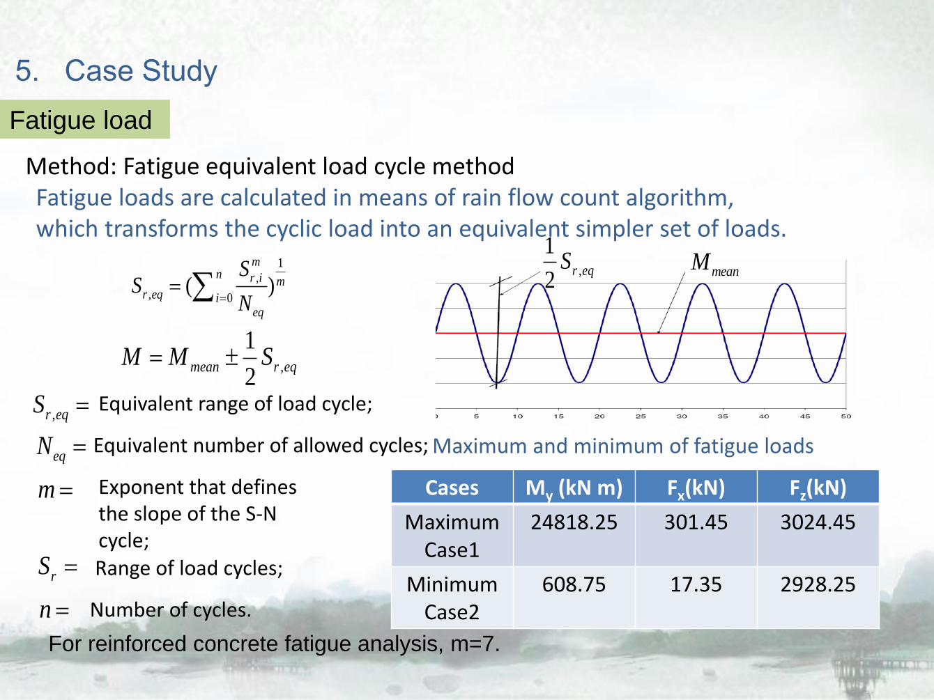
Fatigue load
Method: Fatigue equivalent load cycle method
,
1
2mean r eqM M S
Cases My (kN m) Fx(kN) Fz(kN)
Maximum Case1
24818.25 301.45 3024.45
MinimumCase2
608.75 17.35 2928.25
Maximum and minimum of fatigue loads
1,
, 0( )
mn r i m
r eq ieq
SS
N
Equivalent range of load cycle;,r eqS
Equivalent number of allowed cycles;eqN
m Exponent that defines the slope of the S-N cycle;
rS Range of load cycles;
n Number of cycles.
For reinforced concrete fatigue analysis, m=7.
Fatigue loads are calculated in means of rain flow count algorithm, which transforms the cyclic load into an equivalent simpler set of loads.

5. Case Study
Concrete fatigue analysis
The fatigue life should be verified for compressive concrete under the flange of the anchor ring.
min maxminS maxSIn this project the fatigue analysis is performed separately for concrete and
reinforcement.
Preload values Checking
points
Partial
prestress
P=330kN
Points on the
windward side 2.72 4.73 0.14 0.25
Points on the
leeward side 4.83 6.85 0.25 0.36
Full prestress
P=410kN
Points on the
windward side 3.85 5.86 0.2 0.31
Points on the
leeward side 5.96 7.99 0.31 0.42
Checking points stress of concrete under fatigue analysis
min maxminS maxS
max max / cS fmin min / cS f

5. Case Study
Concrete fatigue verification methods
Code for design of concrete structures (GB50010-2010) only provides fatigue analysis of concrete at 2X10⁶ cycles. Therefore, it’s not suitable to verify fatigue resistance of wind turbine foundations.
The fatigue life of concrete is determined on CEB-FIP Model code 2010 .The fatigue verification for checking points is satisfied.
Wind turbine foundation is subject to high-cyclic load. The number of cycles can be up to 107.
Fatigue life of concrete in accordance with CEB-FIP Model code 2010
Preload value Checking points CEB-FIB MODEL
CODE2010 (lgN)
Partial prestress
P=330kN
Points on the windward side 42.06
Points on the leeward side 31.09
Full prestress
P=410kN
Points on the windward side 36.61
Points on the leeward side 21.94

5. Case Study
Reinforcement fatigue analysis
JL2
JL1Bottom Slab
Stress amplitude Checking points JL1
(N/mm2)
JL2
(N/mm2)
Bottom slab
(N/mm2)
Bending
reinforcement top
Points on the windward side 3.77 9.80 27.96
Points on the leeward side 0 67.94 59.76
Bending
reinforcement
bottom
Points on the windward side 19.08 0 11.23
Points on the leeward side 63.39 68.77 45.06
Checking points stress amplitude of reinforcement under fatigue analysis
Reinforcement fatigue verification methods:
Europe Code 1992-1-1-2004 and CEB-FIP Model
code 2010 both provide damage equivalent stress
range at 107 cycles .
The result shows the reinforcement has sufficient
fatigue resistance.

5. Case Study
Utilization ratiosHighest utilization ratios of the design
Part Strength analysis
Ultimate limit state
Fatigue analysis
Europe code 1992
Bending reinforcement top 0.59 0.64
Bending reinforcement bottom 0.68 0.64
Concrete compression 0.82 0.68
The utilization ratios are calculated by dividing required capacity by
provided capacity.
Limitation
The method ‘Fatigue equivalent load cycle’ is intended for fatigue calculation of components of the wind power plant such as the steel connections. It’s not clear whether it’s reasonable for fatigue analysis of reinforcement concrete.
However, it’s more straightforward because fatigue verification of concrete in Europe code requires one equivalent stress range.

6. Further Work
1. The uncertainties regarding whether ‘Fatigue equivalent load cycle’ can be used for design of reinforced concrete foundation needs to be verified.Fatigue analysis would be more simple through the use of equivalent load.
2.Due to the lack of reasonable S-N curves for concrete, cumulative damage of concrete is hard to evaluate. Fatigue verification methods for turbine foundation require further investigations.
3. Guidelines of partial prestressing and preload loss require further evaluation through on site survey.
4. Dynamic response monitoring of critical elements of turbine foundation needs to be carried out to analyze its fatigue performance afterwards.

Thank you for your attention
Department of Building Engineering, Tongji University, Shanghai, China