Embed Size (px)
Citation preview

International Journal on Soft Computing ( IJSC ) Vol.2, No.4, November 2011
DOI : 10.5121/ijsc.2011.2405 45
Design of Cortical Neuron Circuits With VLSI
Design Approach
A.D.Tete1 and Dr. A.Y.Deshmukh
2
1Research scholar, G.H.Raisoni College of Engg., Nagpur
2Head, Dept.of Electronics G.H.Raisoni College of Engg., Nagpur
[email protected], [email protected]
ABSTRACT
A simple CMOS circuitry using very less number of MOSFETs reproduce most of the electrophysiological
cortical neuron types and is capable of producing a variety of different behaviors with diversity similar to
that of real biological neuron cell. The firing pattern of basic cell classes like regular spiking (RS),
chattering (CH), intrinsic bursting (IB) and fast spiking(FS) are obtained with a simple adjustment of only
one biasing voltage makes circuit suitable for applications in reconfigurable neuromorphic devices that
implement biologically resemble circuit of cortex. This paper discusses spice simulation of the various
spiking pattern ability with required and firing frequency of a given cell type. The circuit operation is
verified for both conditions-constant input and pulsating input.
KEYWORDS
Neocortex, Dendritic morphology, Oscillatory Neuron, Cortical neuron
1. INTRODUCTION
The neocortex is that part of the brain which makes up the outer 2 to 4 mm of the cerebral
hemispheres. It is the “gray matter” of the brain lying atop the cerebral “white matter’ composed
of myelinated axons that interconnect different regions of the brain. All the higher-level
psychophysical functions sensory perception, object and event representation, planning and
decision making are believed to take as their biological substrate the activities of interconnected
and distributed networks of neurons in the neocortex. The cortex structure is very thin and highly
folded with many grooves. All sensory information reaching the neocortex is conveyed through a
sub-cortical (below the cortex) structure called the thalamus. Other signals, thought to be
primarily ‘control’ signals that modulate cortical activity, also come into the neocortex from
approximately 20 sub-cortical regions of the brain. Different regions of the neocortex appear to
be specialized to participate in specific type of psychophysical functions[12]. No single area of
the brain has been successfully identified as the sole functional area of any psycho-physical
phenomenon.

International Journal on Soft Computing ( IJSC ) Vol.2, No.4, November 2011
46
The basic component of the cortical microcircuits are neuron cells. Mimicking it’s operation in
silicon circuits is a subject of ongoing research interest. Analog VLSI model(Very Large Scale of
Integration) of neural circuits provides efficient emulation engines. This could lead in developing
the electronic devices that mimic the operation of biological brain. This ongoing research will
make it possible to make more realistic model of human brain. These models are important tools
for characterizing what nervous system do, determining how they function, and understanding
why they operate in particular ways.
Power consumption and area required to design certain model with least number of transistor is a
fact of adopting the VLSI neural networks that consists of many thousands of neurons.
Growing interest approaches towards the spike-based neural network as they appears to provide
promising solution to a variety of complex problems which can not be solved by most powerful
computers. This paper focuses on the different spiking and firing patterns of the cortical neuron.
Typically used I&F (Integrate &Fire) cells consume approximately 20 transistors to implement
low power adaptive neuron circuitry [4][5]. This is not capable of imitating the processing of
human nervous system, as approximately 90% of the cortex is made of non-linear oscillatory
neuron rather than simple spiking neurons. Therefore work focuses on the utilization of the
minimum number of transistors providing different types of firing patterns obtaining different
types of adaptive and oscillatory neuron behaviors in a single chip.
.
The feature of biological neural network are attributed to it’s structure and function. Fundamental
unit of the network is called a neuron or a nerve cell. It consists of a cell body or soma where the
cell nucleus is located. Tree like nerve fibers called dendrites are associated with the cell body.
These dendrites receives signals from other neurons. Extending from the cell body is a single long
fiber called the axon, which branches into strands and sub strands connecting to many other
neuron at the synaptic junctions or synapses.
Generally the electrical activity is confined to the interior of a neuron, whereas the chemical
mechanism operates at the synapses. The dendrites serve as receptors for signals from other
neurons, whereas the purpose of an axon is transmission of the generated neural activity to other
nerve cell or to muscle fibre..
Artificial neural network (ANN) is a highly simplified model of the structure of the biological
neural network. ANN consists of interconnected processing units. The general model of a
processing unit consist of summing part followed by output part. The summing part receives
u1,u2----un input values(w1,w2----wn) and computes a weighted sum. The weighted sum is
called the activation value. The output part produces a signal from activation value. The sign of
the weight for each input determines whether the input is excitatory(positive weight) or
inhibitory(negative weight). The input could be discrete or continuous data values, and likewise
the output also be deterministic or stochastic or fuzzy.
In an artificial neural network several processing units are interconnected according to some
topology to accomplish a pattern recognition task. Therefore the input to a processing unit may
come from the output of other processing units, and/or from external sources. The output of each
units may be given to several units including itself. The amount of the output of one unit
received by another unit depends on the strength of the connection between the units and it is
reflected in the weight value associated with the connecting links. If there are n activation value
of the network defines the activation state of the network at that instant.
International Journal on Soft Computing ( IJSC ) Vol.2, No.4, November 2011
47
Neurons in the cortex are found with great variety of dendritic morphology, ion channel
distribution and composition. Hence these neurons exhibit different electrical behavior
transforming the same input signal into different firing patterns. Many parameters such as spike
frequency, inter spike interval histogram, spike frequency, adaptation index etc. can be used to
classify the neurons. Approximately 90% of the cortex is made up of non-oscillatory neuron
rather than simple spiking neurons.
Therefore effort has been made for implementing simple neuron circuits that are capable of
providing different types of cortical spiking behavior by utilizing as few transistors as possible to
enable integration of large number of cell in a single chip. The neuronal response to a step
stimulus of supra-threshold current (post synaptic input current that causes action potential)
displays either spiking or bursting firing behavior. The spiking neurons are of two types like
regular spiking (RS) and fast spiking (FS). The RS cell exhibit accommodation property. In
response to a supra-threshold current step they fire repeatedly. The RS cell class can be further
sub-divided into two sub-types—weak accommodating cell are RS1 and strong accommodating
cell are called RS2. Pyramidal cells are an example of RS1 type and and stellate cells are an
example of RS2 type. The FS cells fire repetitively at high frequency with little or negligible
accommodation to a sustained supra-threshold current injection.
The action potential of FS cells exhibit faster rise and fall rates and distinct fast after-
hyperpolarization (AHP) e.g. neocortical small basket cells, bitufted cells and large basket cells.
The basic bursting cell types are chattering (CH) and intrinsic bursting (IB). The CH neurons
usually display repetitive long clusters of spikes. The IB neurons respond to a step current
injection with a cluster of three to five initial spikes followed by an AHP, and then by either
single spikes or burst at more or less regular intervals. These types are observed in sub-population
of bitufted cells, bipolar cells and martinotti cells in the neocortex.
2. VLSI MODEL OF CORTICAL NEURON
Cortical microcircuits are capable of performing sophisticated information processing, handling
high computational throughput of sensory perception, cognitive processes, control and decision
making with low energy consumption. The basic component of the cortical microcircuits are
neuron cells. Mimicking their operation in silicon circuit is the aim of the paper. It is hoped that
analogue VLSI model of neural circuits will provide very efficient brain-inspiredcomputer
architecture. It is an important consideration to design a neuron circuit with the least number of
transistors and with least energy consumption, especially due to the fact that such circuit is
intended to be used in large scale VLSI neural networks that consists of many thousands of
neuron. While considering presently available neuron models the integrate and fire (I&F) neuron
model is widely used due to it’s simplicity – typical I&F neuron cells use approximately 20
transistors to implement low power adaptive neuron circuitry.

International Journal on Soft Computing ( IJSC ) Vol.2, No.4, November 2011
48
Fig.1 Circuit of cortical neuron
However, I & F neurons exhibit simple firing behavior only, this might not be adequate for the
development of VLSI circuitry which would be capable of imitating the processing of the cortex,
which is made up of a large number of more complex non-linear oscillatory neurons exhibiting a
variety of inherent firing patterns. Circuit implementing conductance based neuron model
(Hodgkin-Huxley) consume large number of transistors. The circuit implementation of oscillatory
neuron model Fitzhugh-nagumo, resonate and Fire model, Hindmarsh-Rose uses around 20
transistors. However all these models donot accurately reproduce the shapes of the spikes that
have been observed in biological neurons and are also not capable of generating different types of
spiking and bursting behavior in a single circuit with tunable parameters.
The work presents a simple CMOS circuit model that exploits underlying non-linear
characteristics of MOSFETs to implement the neuron using only 14 transistors. The spiking shape
given by the circuit resembles that of real neurons. The circuit is capable of producing linear and
non-linear responses (firing rate vs. input current) with spike frequency adaptation and a variety
of spiking patterns such as regular spiking, fast spiking, low threshold spiking, intrinsic bursting
etc.
The proposed silicon cortical neuron circuit contains 14 MOSFETs. The two state variables
“membrane potential” (v) and “slow variable” (u), are represented by voltages across capacitors
Cv and Cu respectively. The circuit consists of three functional blocks: membrane potential
circuitry, slow variable circuitry and comparator circuitry.
2.1 Membrane Circuit
Fig.2 – illustrates the membrane potential circuit where the magnitude of the current through M3,
Iv, is controlled by the membrane potential V. Transistors M2 and M3 form a current mirror
circuits, with input current generated by M1. The current Iv acts as a positive feedback to
generate spikes.The current Il is the leakage current generated by M4 and is controlled by the
slow variable U. The current I is the post synaptic input current and it is supplied by an external
synapse. The net sum of these currents is integrated on the membrane capacitor Cv:
International Journal on Soft Computing ( IJSC )
Positive input current leads to the increase in V, which becomes more rapid as V in
generating the spike. Once the spike is detected (by the comparator circuit) a pulse on VA is
generated. Consequently transistor M5 opens and membrane potential voltage is rapidly
hyperpolarized. The transistor M5 is designed so that the capacitor
the VA pulse, thus the value of V after hyper
by the voltage Vc.
2.2 Slow Variable Circuit
The magnitude of the current provided by M7, Ivu is determined by the membrane potential.
Transistor M2 and M7 form a current mirror circuit with input current generated by M1. The
transistors are scaled so that the drain current of transistor M7 is lower
capacitance value of Cu is selected as larger than that of Cv. This ensures that potential U will
vary more slowly than V.
The transistor M6 operates as a non
the slow variable potential U. The net sum of these currents is integrated on the slow variable
capacitor Cu.
Following the membrane potential spike, the comparator generates a pulse, VB to open the
transistor M8, The narrow size of M8 and short duration of pulse VB ensures that the capacitance
rnal on Soft Computing ( IJSC ) Vol.2, No.4, November 2011
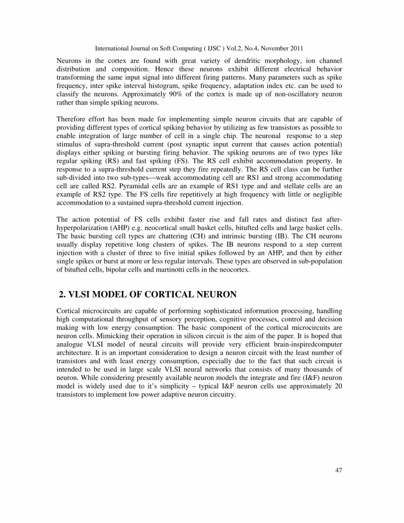
Fig.2 Membrane circuit
Positive input current leads to the increase in V, which becomes more rapid as V in
generating the spike. Once the spike is detected (by the comparator circuit) a pulse on VA is
generated. Consequently transistor M5 opens and membrane potential voltage is rapidly
hyperpolarized. The transistor M5 is designed so that the capacitor Cv is fully discharged during
the VA pulse, thus the value of V after hyper-polarization is entirely determined by the value set
The magnitude of the current provided by M7, Ivu is determined by the membrane potential.
Transistor M2 and M7 form a current mirror circuit with input current generated by M1. The
transistors are scaled so that the drain current of transistor M7 is lower than that of M3 and
capacitance value of Cu is selected as larger than that of Cv. This ensures that potential U will
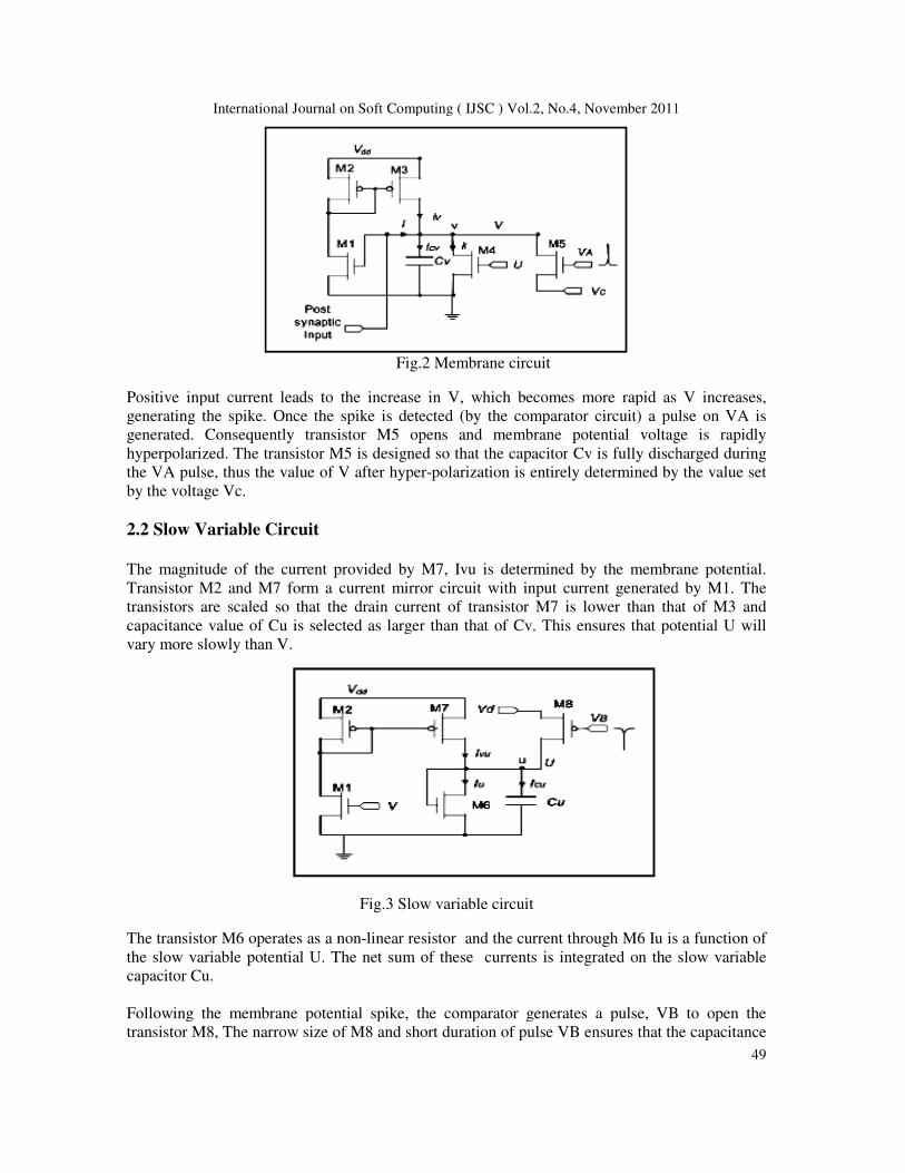
Fig.3 Slow variable circuit
The transistor M6 operates as a non-linear resistor and the current through M6 Iu is a function of
the slow variable potential U. The net sum of these currents is integrated on the slow variable
Following the membrane potential spike, the comparator generates a pulse, VB to open the
of M8 and short duration of pulse VB ensures that the capacitance
Vol.2, No.4, November 2011
49
Positive input current leads to the increase in V, which becomes more rapid as V increases,
generating the spike. Once the spike is detected (by the comparator circuit) a pulse on VA is
generated. Consequently transistor M5 opens and membrane potential voltage is rapidly
Cv is fully discharged during
polarization is entirely determined by the value set
The magnitude of the current provided by M7, Ivu is determined by the membrane potential.
Transistor M2 and M7 form a current mirror circuit with input current generated by M1. The
than that of M3 and
capacitance value of Cu is selected as larger than that of Cv. This ensures that potential U will
M6 Iu is a function of
the slow variable potential U. The net sum of these currents is integrated on the slow variable
Following the membrane potential spike, the comparator generates a pulse, VB to open the
of M8 and short duration of pulse VB ensures that the capacitance

International Journal on Soft Computing ( IJSC )
Cu is not fully reset to Vd, but instead an extra amount of charge, controlled by Vd, is transferred
onto Cu. Therefore each membrane spike provides a quick increase in the slow variable pot
which in turn increases the leakage current of the membrane potential and slow down the
depolarization after the spike. This mechanism is used to provide the accommodation property of
the spike train.
2.3 Comparator
The comparator circuit is shown in Fig. 4. The voltage Vth is the spike
membrane potential. The voltage Vbias controls the
membrane potential increases above Vth, the voltage at VB is decreased and VA is increased,
generating reset signals. Due to limited speed of comparator and switches the reset is delayed, so
the membrane potential V continues to increase beyond Vth, and onto VDD, but once VA is
increased, the membrane potential is reset to Vc which is lower than Vth. Consequently, voltages
VA and VB return to their reset voltage level, completing reset pulse. The transistor M14
increases the comparator current during the spike, providing the required amplitude and duration
of the reset pulse VB.
3. SIMULATION RESULTS
Fig .3.1 Regular spiking pattern(RS)
rnal on Soft Computing ( IJSC ) Vol.2, No.4, November 2011
Cu is not fully reset to Vd, but instead an extra amount of charge, controlled by Vd, is transferred
onto Cu. Therefore each membrane spike provides a quick increase in the slow variable pot
which in turn increases the leakage current of the membrane potential and slow down the
depolarization after the spike. This mechanism is used to provide the accommodation property of
Fig.4 Comparator circuit
The comparator circuit is shown in Fig. 4. The voltage Vth is the spike-detection threshold of the
membrane potential. The voltage Vbias controls the bias current in the comparator. When the
membrane potential increases above Vth, the voltage at VB is decreased and VA is increased,
generating reset signals. Due to limited speed of comparator and switches the reset is delayed, so
continues to increase beyond Vth, and onto VDD, but once VA is
increased, the membrane potential is reset to Vc which is lower than Vth. Consequently, voltages
VA and VB return to their reset voltage level, completing reset pulse. The transistor M14
eases the comparator current during the spike, providing the required amplitude and duration
3. SIMULATION RESULTS
Fig .3.1 Regular spiking pattern(RS)
Vol.2, No.4, November 2011
50
Cu is not fully reset to Vd, but instead an extra amount of charge, controlled by Vd, is transferred
onto Cu. Therefore each membrane spike provides a quick increase in the slow variable potential
which in turn increases the leakage current of the membrane potential and slow down the
depolarization after the spike. This mechanism is used to provide the accommodation property of
detection threshold of the
bias current in the comparator. When the
membrane potential increases above Vth, the voltage at VB is decreased and VA is increased,
generating reset signals. Due to limited speed of comparator and switches the reset is delayed, so
continues to increase beyond Vth, and onto VDD, but once VA is
increased, the membrane potential is reset to Vc which is lower than Vth. Consequently, voltages
VA and VB return to their reset voltage level, completing reset pulse. The transistor M14
eases the comparator current during the spike, providing the required amplitude and duration

International Journal on Soft Computing ( IJSC ) Vol.2, No.4, November 2011
51
As the name suggests Regular Spiking (RS) gives a single spike output repeated at regular
intervals. In the result shown above the spike repetition rate is once every 0.25ms. which in terms
of frequency is 4KHz. The step input for this simulation is 2nA. It is seen that the firing pattern of
VLSI neuron are on the millisecond scale of biological neuron. Regular spiking pattern Vd to be
set to 2.07V. Threshold voltage at the comparator stage of the cortical neuron is set to 1.4V and
the bias voltage Vc is set to 0.6V which is kept constant for all firing patterns . Single spike is
necessary for the neuron to fire. It is generally observed in the mammalian neocortex.
Fig.3.2 Intrinsic bursting spiking pattern(IB1 andIB2)
Intrinsical Bursting (IB) is a pattern in which more than one spikes or a Burst is repeated at
regular intervals. Top trace of Fig. 3.2 shows the output obtained when Vd is kept at 2.02V while
the trace below it is for Vd=2.0V, the input remaining the same in both the cases. Once again the
spike burst repetition rate is once every 0.25ms, which in terms of frequency is 4KHz. The step
input for this simulation is 2nA. It is observed that when the Vd is 2.02 there is mixed type of
spiking burst as well as single spike, this kind of patterns generally observed in the mammalian
neocortex.

International Journal on Soft Computing ( IJSC ) Vol.2, No.4, November 2011
52
Fig.3.3 Intrinsic bursting spiking pattern(IB3 and IB4)
Intrinsical Bursting (IB3 and IB4) is a pattern in which more than two spikes or a Burst is
repeated at regular intervals. Top trace of Fig. 3.3 shows the output obtained when Vd is kept at
1.6V while the trace below it is for Vd=1.4V, the input remaining the same in both the cases.
Once again the spike burst repetition rate is once every 0.25ms, which in terms of frequency is
4KHz. The step input for this simulation is 2nA. It is observed that as Vd goes on decreasing
more number spikes are required to fire the neuron. Some neurons such as the chattering neuron
in cat neocortex fire periodic burst of spikes when simulated. The interburst (between burst)
frequency is very high and it is believed that such neurons contributes to the gamma frequency
oscillation in the brain.
Fig. 3.4 Chattering type spiking pattern(CH1 and CH2)
Chattering type (CH1 and CH2) is a pattern in which more than five to ten spikes or a Burst is
repeated at irregular intervals. Accommodation period depend upon the number of spike required
to fire the neuron. Top trace of Fig. 3.4 shows the output obtained when Vd is kept at 1.39V

International Journal on Soft Computing ( IJSC ) Vol.2, No.4, November 2011
53
while the trace below it is for Vd=1.35V, the input remaining the same in both the cases. Once
again the spike burst repetition rate is once every 0.5ms which in terms of frequency is 2KHz.
The step input for this simulation is 2nA. It is observed that as Vd goes on decreasing more
number spikes are required to fire the neuron. The interburst (between burst) frequency is very
high.
Fast spiking cell fire repetitively at high frequency with less or no accommodation to a sustained
suprathreshold current. Step input of 2nA is given to the cortical neuron with Supply voltage is
set at 3V. Threshold voltage for comparison is set at 1.4V while biasing is 0.4V. The control
voltage Vd is set to 1.3V for top trace and 1.0V for later trace. As Vd is decreased to sufficient
low level compared to RS pattern it is observed that there is no accommodation for the spikes that
capacitor Cu does not get sufficient time to get discharge and at the output fast spiking pattern is
observed.
Fig.3.5 Fast spiking pattern(FS1 and FS2)
Table 1. Comparison of various spiking patterns of Cortical Neuron
International Journal on Soft Computing ( IJSC ) Vol.2, No.4, November 2011
54
The circuits have been designed in a 1.25um CMOS technology. The simulation results of the
circuits illustrates various types of cortical neuron firing patterns, obtained by changing the value
of circuit variable Vd keeping Vc constant which are externally controllable. It is observed that
with decreasing Vd the amount of charge transferred to slow variable capacitor decreases. Thus
the capacitor charging time increases. The time till the capacitor voltage value reaches the
threshold level fast spikes are continuously available at the output. Therefore decreasing Vd
causes longer period of spikes and shorter duration of spike off or reset. Eventually at Vd=1.3 the
capacitor no longer reaches the threshold value and hence the reset due to slow variable does not
occur. This causes continuous spikes to be available at the output. The patterns of VLSI neurons
are on the millisecond scale of biological neurons. For comparative purposes, all the
classifications are done in the time scaled domain in order to adopt biological classification
method.
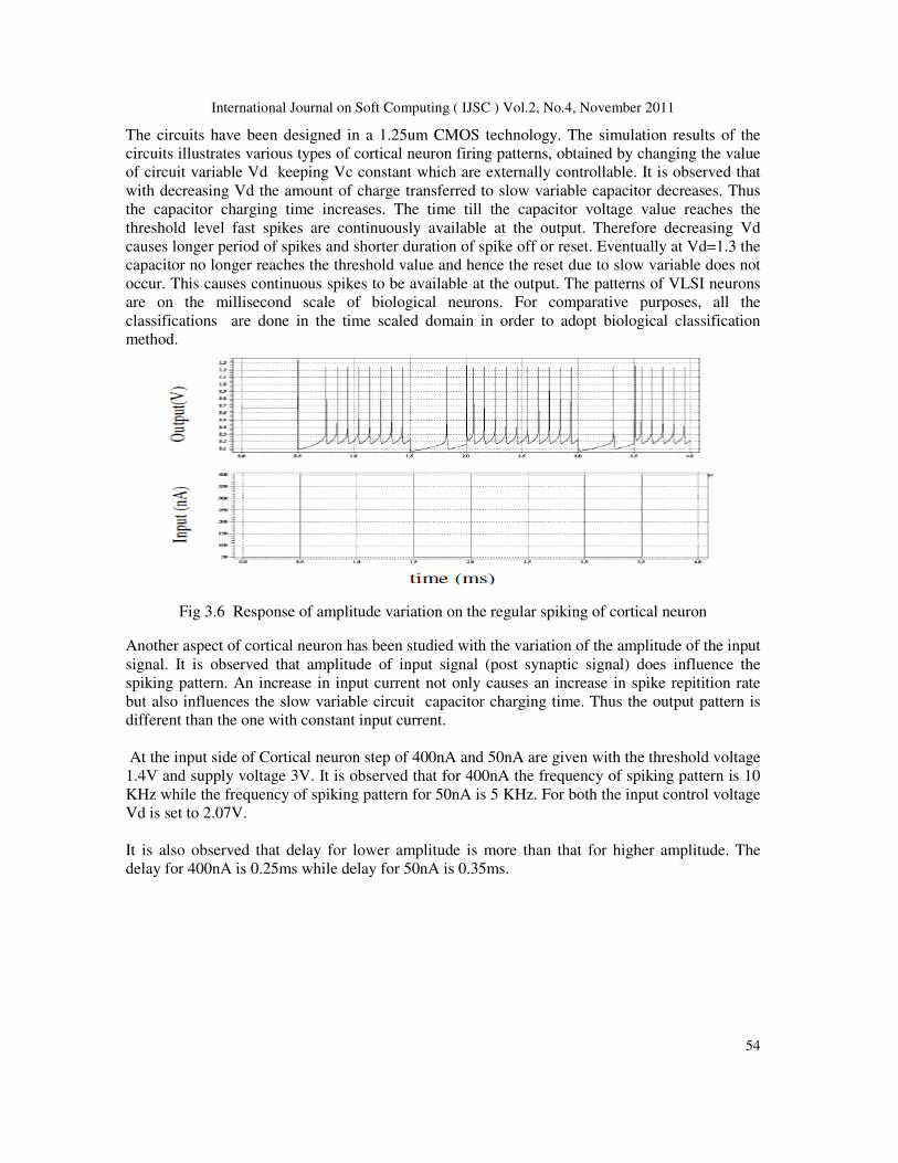
Fig 3.6 Response of amplitude variation on the regular spiking of cortical neuron
Another aspect of cortical neuron has been studied with the variation of the amplitude of the input
signal. It is observed that amplitude of input signal (post synaptic signal) does influence the
spiking pattern. An increase in input current not only causes an increase in spike repitition rate
but also influences the slow variable circuit capacitor charging time. Thus the output pattern is
different than the one with constant input current.
At the input side of Cortical neuron step of 400nA and 50nA are given with the threshold voltage
1.4V and supply voltage 3V. It is observed that for 400nA the frequency of spiking pattern is 10
KHz while the frequency of spiking pattern for 50nA is 5 KHz. For both the input control voltage
Vd is set to 2.07V.
It is also observed that delay for lower amplitude is more than that for higher amplitude. The
delay for 400nA is 0.25ms while delay for 50nA is 0.35ms.

International Journal on Soft Computing ( IJSC ) Vol.2, No.4, November 2011
55
Fig 3.7 Response of amplitude variation on the intrinsic bursting of cortical neuron
Another spiking pattern (CH2 and IB2) for different amplitude and different control voltage is
studied. At the input side of Cortical neuron step of 400nA and 50nA are given with the threshold
voltage 1.4V and supply voltage 3V. It is observed that for 400nA the frequency of spiking
pattern is high while the inter-spike frequency of spiking pattern for 50nA is 6.6 KHz. For both
the input control voltage Vd is set to 2.0V. It is also observed that delay for lower amplitude is
less than that for higher amplitude. The delay for 400nA is 0.25ms while delay for 50nA is
0.15ms.
Fig 3.8 Response of amplitude variation on the fast spiking (FS1) of cortical neuron
Another spiking pattern (FS1 and RS1) for different amplitude and different control voltage is
studied. At the input side of Cortical neuron step of 400nA and 50nA are given with the
threshold voltage 1.4V and supply voltage 3V. It is observed that for 400nA the frequency of
spiking pattern is high while the spike frequency of spiking pattern for 50nA is 6.6 KHz. For both
the input control voltage Vd is set to 1.39V.
It is also observed that delay for lower amplitude is more than that for higher amplitude. The
delay for 400nA is 0ms while delay for 50nA is 0.4ms.
International Journal on Soft Computing ( IJSC ) Vol.2, No.4, November 2011
56
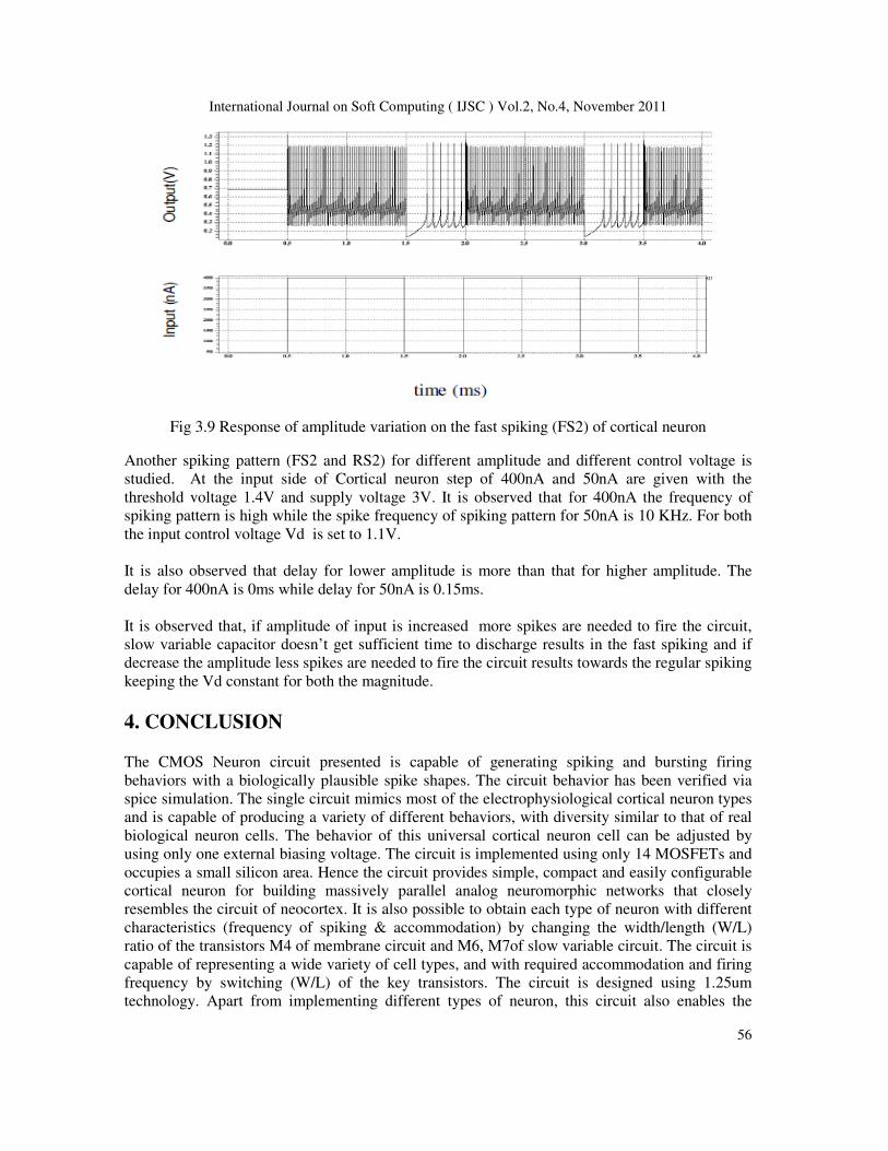
Fig 3.9 Response of amplitude variation on the fast spiking (FS2) of cortical neuron
Another spiking pattern (FS2 and RS2) for different amplitude and different control voltage is
studied. At the input side of Cortical neuron step of 400nA and 50nA are given with the
threshold voltage 1.4V and supply voltage 3V. It is observed that for 400nA the frequency of
spiking pattern is high while the spike frequency of spiking pattern for 50nA is 10 KHz. For both
the input control voltage Vd is set to 1.1V.
It is also observed that delay for lower amplitude is more than that for higher amplitude. The
delay for 400nA is 0ms while delay for 50nA is 0.15ms.
It is observed that, if amplitude of input is increased more spikes are needed to fire the circuit,
slow variable capacitor doesn’t get sufficient time to discharge results in the fast spiking and if
decrease the amplitude less spikes are needed to fire the circuit results towards the regular spiking
keeping the Vd constant for both the magnitude.
4. CONCLUSION
The CMOS Neuron circuit presented is capable of generating spiking and bursting firing
behaviors with a biologically plausible spike shapes. The circuit behavior has been verified via
spice simulation. The single circuit mimics most of the electrophysiological cortical neuron types
and is capable of producing a variety of different behaviors, with diversity similar to that of real
biological neuron cells. The behavior of this universal cortical neuron cell can be adjusted by
using only one external biasing voltage. The circuit is implemented using only 14 MOSFETs and
occupies a small silicon area. Hence the circuit provides simple, compact and easily configurable
cortical neuron for building massively parallel analog neuromorphic networks that closely
resembles the circuit of neocortex. It is also possible to obtain each type of neuron with different
characteristics (frequency of spiking & accommodation) by changing the width/length (W/L)
ratio of the transistors M4 of membrane circuit and M6, M7of slow variable circuit. The circuit is
capable of representing a wide variety of cell types, and with required accommodation and firing
frequency by switching (W/L) of the key transistors. The circuit is designed using 1.25um
technology. Apart from implementing different types of neuron, this circuit also enables the

International Journal on Soft Computing ( IJSC ) Vol.2, No.4, November 2011
57
designing of a variety of different behavioral cell clusters in each cortical neuron types, with
diversity similar to that of biological neuron cells. The variety of behavior is obtained in a single
circuit only requiring changing one bias voltage. This voltage can be set externally or could be
stored/controlled locally enabling dynamic switching of spiking modes and characteristics.
REFERENCES
[1] Hsin Chen, Sylvain Saighi, Laure Bahry and Sylvie Renaud,”Real Time Simulation of Biologically
Realistic Stochastic Neurons in VLSI”, IEEE Transaction on Neural Networks, Vol 21, No. 9,
September 2010.
[2] Hongbo Jia,, Nathalie L.Rochefort, Xiaowei Chen and Arthur Konnerth, “Dendritic Organization of
Sensory Input to Cortical Neuron in Vivo”, Vol 464/29 April 2010/doi:10.1038/nature 08947.
[3] Jayawan H.B Wijekoon, Piotri Dudek, “Compact Silicon Neuron Circuit with Spiking and Bursting
Behaviours”, Science Direct, Neural Networks 21 (2008) 524-534.
[4] Chiara Bartolozzi and Giacomo Indiveri, “Synaptic dynamics in analog VLSI”, Neural computation
19, 2581-2603(2007)
[5] Jayawan H.B.Wijekoon and Piotr Dudek, “Spiking and bursting firing pattern of a compact
VLSI Cortical neuron circuit”, International joint conference on Neural-Network, Oriando,
Florida, USA, Aug 12-17,2007
[6] Mircea I.Chelaru and Valentin Dragoi, “Asymmetric synaptic depression in cortical networks”,
Cerebral cortex advance access published August 9,2007.
[7] Richard B.Wells, “Cortical Neurons and Circuits, A Tutorial Introduction”, April 2005.
[8] G.Indiveri, “A low power adaptive integrate-and-fire neuron circuit.” IEEE Int.Symp.circuits and
systems, ISCAS, pp IV820-823,2003.
[9] Y.Kanazawa, T.Asai and Y.Amemiya, “A hardware depressing synapse and it’s application to
contrast-invariant pattern recognition”.vol 102,no.729(NC 2002 134-171) 2003 Japan
[10] Shih-Chii Liu, “Analog VLSI circuits for short-term dynamic synapses”, EURASIP journal rev. 25-
sep-2002.
[11] S.R.Schultz and M.A.Jabri, “ Analogue VLSI integrated-fire neuron with frequency
adaptation”,Electronic Letters, vol.31, no.16, pp.1357-1358, Aug 1995.
[12] R.Douglas, M.Mahowald, and C.Mead, “Neuromorphic analogue VLSI”, Ann.Rev.Neurosci, Vol. 18,
pp.255-281,1995.
[13] J.P.Lazzaro, “Low-power silicon axons, neurons, and synapses”, in silicon implementation of pulse
coded neural networks, m.E.Zaghloul, J.L.Meador, and R.W.New-comb, Eds.,pp.153-164. Kluwer
Academic Publishers, Norwell, MA, 1994.
[14] B.L.Barranco, E.S.Sinencio, A.R.Vazquez, and J.L.Huertas, “A CMOS implementation of Fitz-Hugh-
Nagumo neuron model”, IEEE Journal Solid-State Circuits, Vol.26,pp.956-965,1991.
[15] M.Mahowald and R.Douglas, “A silicon neuron”, Nature, vol.354,no.6354,pp.515-518,1991