Embed Size (px)
Citation preview
Design of Compact Circular Disc Circularly Polarized Antenna with Koch Curve
Fractal Defected Ground Structure
P. R. Prajapati*1, G. G. K. Murthy2, A. Patnaik3 and M. V. Kartikeyan4
Millimeter Wave Laboratory, Department of Electronics and Communication Engineering, Indian Institute of Technology, Roorkee-247667, India1,2,3,4
Ph: 91-1332-286453, Fax: 91-1332-285368
Email: [email protected], [email protected], [email protected]
Abstract A circularly polarized microstrip patch antenna with Koch curve fractal defected ground structure (DGS) for mobile applications is presented. Asymmetric ‘+’ shape slots are incorporated on circular patch for getting circular polarization. The advantages of incorporation of Koch curve fractal DGS for improvement of performance parameters of circular polarized antenna presented. It is shown that with every progressive stage of fractal DGS iteration, in addition to reduction in size of the patch, other performance parameters of the antenna such as 3 dB axial ratio bandwidth, 10 dB impedance bandwidth and radiation efficiency also show significant improvement in their values at cost of marginal reduction of the gain. The design, evaluation and comparison of the proposed antenna with conventional simple circular disc circular polarized antenna without DGS along with intermediate and final iterations of Koch curve fractal DGS are illustrated.
1. Introduction Circularly polarized (CP) antennas are drawing the attention of present era of wireless communication systems because of their inherent advantages of immunity to the multipath fading channel and flexibility of alignment between the receiver and transmitter antennas. Due to the tremendous increase in the use of hand held communication devices and systems in which antenna is an essential integral part, the design of an antenna in a very efficient way for these applications has always been a fresh challenge despite a lot of research going on in this area. To improve the design of the antenna, various techniques [1-3], such as use of substrate with high dielectric constant, slots on the patch, using fractals, DGS, Electronic Band gap structures (EBG), metamaterials, shorting plates and shorting pins have been proposed in the open literature to obtain miniaturization of antenna with not much more affecting its other parameters significantly. Another technique of miniaturization of the patch size is a combination of defected ground structure (DGS) and fractal geometry. The present technique proposed in this paper, makes the use of self-similar shapes to etch the ground plane, which in turn acts as DGS and hence the name of this technique is “Fractal-DGS”. This technique for miniaturization of patch size was exploited in various disciplines such as design of microwave filters [4-5], design based on micro electro-mechanical system (MEMS) for miniaturization of microstrip antenna array [6], telemedicine applications [7], emergency management applications [8], etc. Till now, as far as the knowledge of the author is concerned, the size miniaturization of patch antenna using fractal DGS in the design of CP microstrip patch antennas has not been fully explored.
2. Design Methodology The geometry of the proposed antenna is shown in Fig. 1. Proximity coupling was used to feed the antenna. The width of the feed line is 4.5 mm and the length of the feed line is 45 mm. The width of the feed line has been calculated using analytical line impedance calculator given in CST Microwave Studio simulator, version 12. Two slots of unequal lengths were made in the circular patch in the form of a cross so that it helps to generate two orthogonal resonant modes, which have almost equal amplitude and nearly 90⁰ phase difference at the center frequency of 1.5 GHz, for realization of circular polarization. The dimensions of the fractal DGS are enumerated in Fig. 1 (c). For a design and optimization of antenna parameters, CST Microwave Studio simulator, version 12 [9] was used. The design flow chart depicting various stages of iterations in the Koch curve fractal-DGS in the ground plane, resulting in the evolution the final proposed antenna is shown in Fig. 2. It is shown that as the order of iteration increases, the electrical length on the ground plane increases, resulting in a decrease in the size of the patch without change in the resonant frequency of 1.5 GHz.
978-1-4673-5225-3/14/$31.00 ©2014 IEEE

Fig. 1 (a) Cross-sectional view of the proposed antenna. (b) Top view of the proposed antenna. (c) Bottom view of the proposed antenna. (d) Expanded view of the proposed 2nd iteration Koch curve Fractal-DGS with the following parameters: P = 34 mm; R = √3 P/2 = 29.44 mm.
(a) 0th iteration (b) 1st iteration (c) Proposed 2nd iteration.
Fig. 2 Design flow chart describing various stages of iteration of Koch curve fractal-DGS.
3. Results and Discussion
3.1 3 dB Axial Ratio (AR) Bandwidth and 10 dB Impedance Bandwidth
Fig. 3 shows that as the stage of iteration of Koch curve fractal DGS increases, the AR bandwidth increases. The simulated 3 dB AR bandwidth for the proposed antenna was found to be 31.52 MHz, from 1.488 GHz to 1.520 GHz, i.e. 2.1% around the center frequency of 1.5 GHz; whereas only AR bandwidth of 19.27 MHz, from 1.491 GHz to 1.510 GHz i.e. 1.28% at the center frequency of 1.5 GHz obtained using simple circular disc CP antenna. It was observed that the addition of 2nd iteration Koch curve Fractal-DGS leads to an increase in the 3 dB AR bandwidth by 62.73% over conventional antenna without DGS. The minimum AR of 0.81 dB obtained at the center frequency of 1.5 GHz using the proposed design.
Fig. 4 shows that without DGS, conventional circular disc CP antenna has 10 dB impedance bandwidth of 66.5 MHz (1.472 GHz-1.538 GHz). After incorporation of 2nd iteration Koch curve fractal DGS, 10 dB impedance bandwidth increases by 70.74% (i.e. 113.68 MHz) ranging from 1.461 GHz-1.575 GHz. It can be seen that this frequency band covers the range of frequencies over which the axial ratio is less than 3 dB, hence satisfying the requirements of the goal of the design of the compact CP antenna for mobile application.
Fig. 3 Simulated Axial Ratio characteristics Fig. 4 Comparison of simulated S11
for different iterations of DGS . characteristics between conventional antenna without DGS and the proposed antenna.
3.2 Radiation Efficiency and Gain
Due to band stop characteristics of DGS at the higher frequency band, higher harmonics of a conventional CP antenna without DGS have been suppressed. The suppression of higher harmonics leads to increment of the radiation
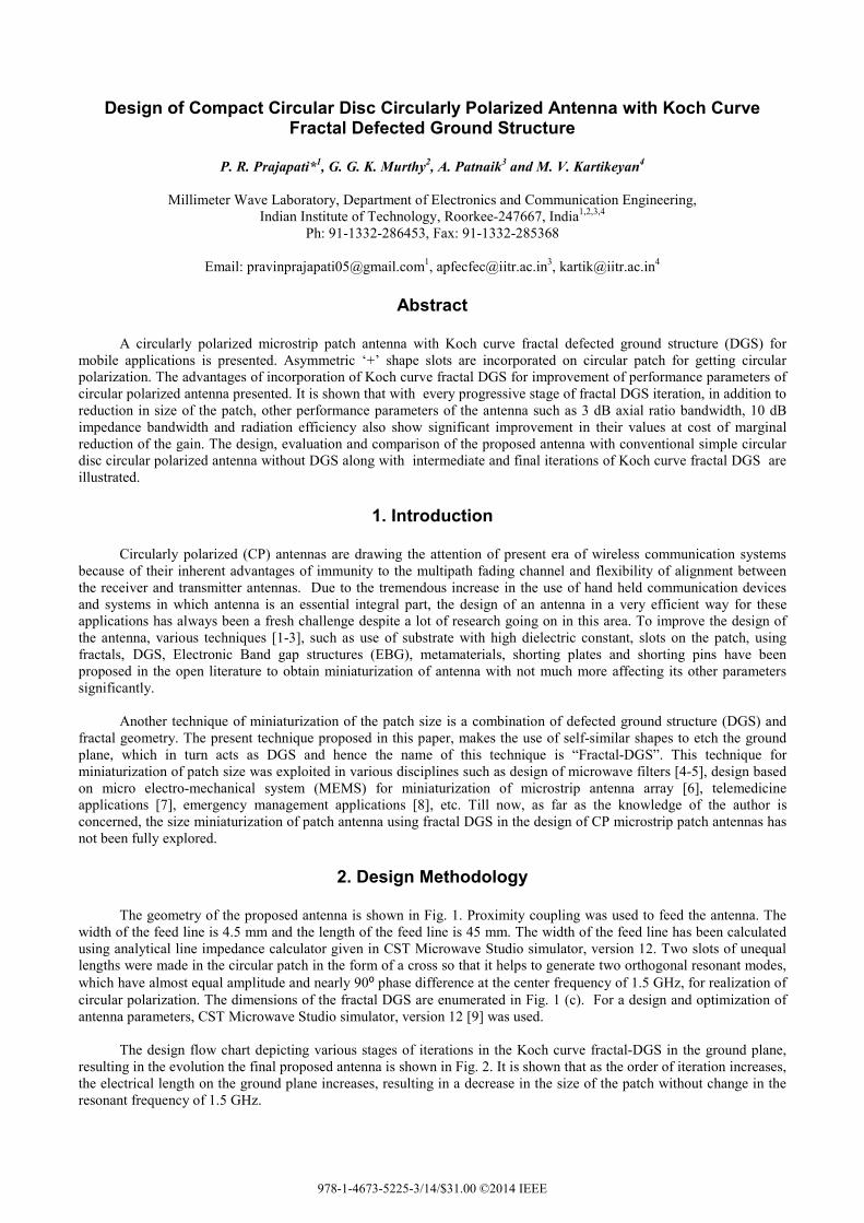
efficiency. As seen in Fig. 5, as the stage of iteration increases, the radiation efficiency also increases. The simulated the radiation efficiency of the proposed antenna is found to be 92.26% at 1.5 GHz; whereas the simulated radiation efficiency of the conventional antenna was 88.23% at 1.5 GHz. It was observed that, the addition of 2nd koch curve fractal-DGS leads to an increase in the radiation efficiency by 4.03% over conventional antenna without DGS at the center frequency of 1.5 GHz. As DGS radiates at back direction, the gain of the antenna decreases. The simulated gain of the proposed antenna was found to be 5.41 dB at the center frequency of 1.5 GHz. It can be seen from Fig. 6 that the decrement in gain is only 14.66% (6.34 dB to 5.41 dB) at 1.5 GHz in the case of the proposed antenna over the conventional antenna without DGS. Still the gain of the proposed antenna is more than 5 dB over the entire band in which the axial ratio is less than 3 dB.
Fig. 5 Comparison of simulated radiation efficiency Fig. 6 Comparison of simulated gain vs. vs. frequency with different iterations of DGS. frequency with different iterations of DGS.
3.3 Radiation Patterns
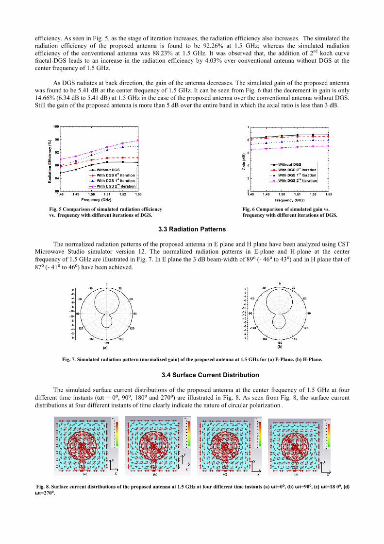
The normalized radiation patterns of the proposed antenna in E plane and H plane have been analyzed using CST Microwave Studio simulator version 12. The normalized radiation patterns in E-plane and H-plane at the center frequency of 1.5 GHz are illustrated in Fig. 7. In E plane the 3 dB beam-width of 89⁰ (- 46⁰ to 43⁰) and in H plane that of 87⁰ (- 41⁰ to 46⁰) have been achieved.
Fig. 7. Simulated radiation pattern (normalized gain) of the proposed antenna at 1.5 GHz for (a) E-Plane. (b) H-Plane.
3.4 Surface Current Distribution
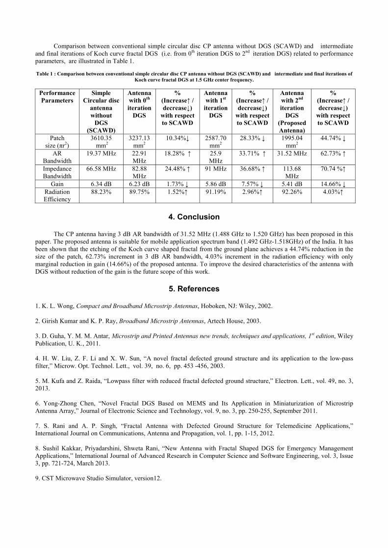
The simulated surface current distributions of the proposed antenna at the center frequency of 1.5 GHz at four different time instants (ωt = 0⁰, 90⁰, 180⁰ and 270⁰) are illustrated in Fig. 8. As seen from Fig. 8, the surface current distributions at four different instants of time clearly indicate the nature of circular polarization .
Fig. 8. Surface current distributions of the proposed antenna at 1.5 GHz at four different time instants (a) ωt=0⁰, (b) ωt=90⁰, (c) ωt=18 0⁰, (d) ωt=270⁰.
Comparison between conventional simple circular disc CP antenna without DGS (SCAWD) and intermediate and final iterations of Koch curve fractal DGS (i.e. from 0th iteration DGS to 2nd iteration DGS) related to performance parameters, are illustrated in Table 1.
Table 1 : Comparison between conventional simple circular disc CP antenna without DGS (SCAWD) and intermediate and final iterations of
Koch curve fractal DGS at 1.5 GHz center frequency.
Performance Parameters
Simple Circular disc
antenna without
DGS (SCAWD)
Antenna with 0th iteration
DGS
% (Increase↑ / decrease↓)
with respect to SCAWD
Antenna with 1st
iteration DGS
% (Increase↑ / decrease↓)
with respect to SCAWD
Antenna with 2nd iteration
DGS (Proposed Antenna)
% (Increase↑ / decrease↓)
with respect to SCAWD
Patch size (πr2)
3610.35 mm2
3237.13 mm2
10.34%↓ 2587.70 mm2
28.33% ↓ 1995.04 mm2
44.74% ↓
AR Bandwidth
19.37 MHz 22.91 MHz
18.28% ↑ 25.9 MHz
33.71% ↑ 31.52 MHz 62.73% ↑
Impedance Bandwidth
66.58 MHz 82.88 MHz
24.48% ↑ 91 MHz 36.68% ↑ 113.68 MHz
70.74 %↑
Gain 6.34 dB 6.23 dB 1.73% ↓ 5.86 dB 7.57% ↓ 5.41 dB 14.66% ↓ Radiation Efficiency
88.23% 89.75% 1.52%↑ 91.19% 2.96%↑ 92.26% 4.03%↑
4. Conclusion
The CP antenna having 3 dB AR bandwidth of 31.52 MHz (1.488 GHz to 1.520 GHz) has been proposed in this paper. The proposed antenna is suitable for mobile application spectrum band (1.492 GHz-1.518GHz) of the India. It has been shown that the etching of the Koch curve shaped fractal from the ground plane achieves a 44.74% reduction in the size of the patch, 62.73% increment in 3 dB AR bandwidth, 4.03% increment in the radiation efficiency with only marginal reduction in gain (14.66%) of the proposed antenna. To improve the desired characteristics of the antenna with DGS without reduction of the gain is the future scope of this work.
5. References
1. K. L. Wong, Compact and Broadband Microstrip Antennas, Hoboken, NJ: Wiley, 2002. 2. Girish Kumar and K. P. Ray, Broadband Microstrip Antennas, Artech House, 2003. 3. D. Guha, Y. M. M. Antar, Microstrip and Printed Antennas new trends, techniques and applications, 1st edition, Wiley Publication, U. K., 2011. 4. H. W. Liu, Z. F. Li and X. W. Sun, “A novel fractal defected ground structure and its application to the low-pass filter,” Microw. Opt. Technol. Lett., vol. 39, no. 6, pp. 453 -456, 2003. 5. M. Kufa and Z. Raida, “Lowpass filter with reduced fractal defected ground structure,” Electron. Lett., vol. 49, no. 3, 2013. 6. Yong-Zhong Chen, “Novel Fractal DGS Based on MEMS and Its Application in Miniaturization of Microstrip Antenna Array,” Journal of Electronic Science and Technology, vol. 9, no. 3, pp. 250-255, September 2011. 7. S. Rani and A. P. Singh, “Fractal Antenna with Defected Ground Structure for Telemedicine Applications,” International Journal on Communications, Antenna and Propagation, vol. 1, pp. 1-15, 2012. 8. Sushil Kakkar, Priyadarshini, Shweta Rani, “New Antenna with Fractal Shaped DGS for Emergency Management Applications,” International Journal of Advanced Research in Computer Science and Software Engineering, vol. 3, Issue 3, pp. 721-724, March 2013. 9. CST Microwave Studio Simulator, version12.