Embed Size (px)
Citation preview

1
Design of Columns
Introduction
According to ACI Code 2.2, a structural element with a ratio of height-to-least lateral dimension exceeding three used primarily to support compressive loads is defined as column. Columns support vertical loads from the floor and roof slabs and transfer these loads to the footings.
Columns usually support compressive loads with or without bending. Depending on the magnitude of the bending moment and the axial force, column behavior will vary from pure beam action to pure column action.
Columns are classified as short or long depending on their slenderness ratios. Short columns usually fail when their materials are overstressed and long columns usually fail due to buckling which produces secondary moments resulting from the ∆−P effect.
Columns are classified according to the way they are reinforced into tied and spirally reinforced columns. Columns are usually reinforced with longitudinal and transverse reinforcement. When this transverse reinforcement is in the form of ties, the column is called “tied”. If the transverse reinforcement is in the form of helical hoops, the column is called “spirally reinforced”.
Since failure of columns often cause extensive damage, they are designed with a higher factor of safety than beams.
Types of Columns
Columns are divided into three types according to the way they are reinforced.
Tied Columns
A tied column, shown in Figure 1, is a column in which the longitudinal reinforcement bars are tied together with separate smaller diameter transverse bars (ties) spaced at some interval along the column height. These ties help to hold the longitudinal reinforcement bars in place during construction and ensure stability of these bars against local buckling. The cross sections of such columns are usually square, rectangular, or circular in shape. A minimum of four bars is used in rectangular and circular cross sections.

2
Figure 1: Tied column
Spirally-Reinforced Columns
They are columns in which the longitudinal bars are arranged in a circle surrounded by a closely spaced continuous spiral, shown in Figure 2. These columns are usually circular or square in shape. A minimum of six bars is used for longitudinal reinforcement.
Figure 2: Spirally-reinforced column
Composite Columns
A composite column is a column made of structural steel shapes or pipes surrounded by or filled by concrete with or without longitudinal reinforcement, shown in Figure 3.

3
Figure 3:Composite column
Behavior of Tied and Spirally-Reinforced Columns
Axial loading tests have proven that tied and spirally reinforced columns having the same cross-sectional areas of concrete and steel reinforcement behave in the same manner up to the ultimate load, as shown in Figure 4.a. At that load tied columns fail suddenly due to excessive cracking in the concrete section followed by buckling of the longitudinal reinforcement between ties within the failure region, as shown in Figure 4.b.
(a)

4
(b)
Figure 4: Failure of columns; (a) behavior of tied and spirally-reinforced columns; (b) failure of columns
For spirally reinforced columns, once the ultimate load is reached, the concrete shell covering the spiral starts to peel off. Only then, the spiral comes to action by providing a confining force to the concrete core, thus enabling the column to sustain large deformations before final collapse occurs.
Factored Loads and Strength Reduction Factors
Factored Loads
Load factors for dead, live, wind or earthquake live loads combinations are shown in Table 1.
Table 1: Required Strength for simplified load combinations
Loads Required Strength Equation NO.
Dead (D) and Live (L) D4.1
LD 6.12.1 +
(1.1)
(1.2)
Dead (D), Live (L) and wind (W)
LD 0.12.1 +
WD 8.02.1 +
LWD 0.16.12.1 ++
WD 6.19.0 +
(1.3)
(1.3)
(1.4)
(1.6)
Dead (D), Live (L) and Earthquake (E)
ELD 0.10.12.1 ++
ED 0.19.0 +
(1.5)
(1.7)
Strength Reduction Factors
According to ACI 9.3.2 strength reduction factors Φ for compression-controlled sections are given as follows:
• Members with spiral reinforcement Φ = 0.75

5• Other reinforced members Φ = 0.65
The basic equation is given by
nu PP Φ≤ (1)
where
uP = factored axial load
Φ = strength reduction factor
nP = nominal axial load
Short Axially Loaded Columns
Figure 5: Uniaxial stress-strain curves for steel and concrete
When axial compressive loads are applied through the centroid of the cross section of a short column, concrete and steel reinforcement are shortened by the same amount due to their composite action. The ultimate load is attained when the reinforcement reaches its yield stress and the concrete reaches its 28-day compressive strength simultaneously, shown in Figure 5.
From equilibrium of forces in the vertical direction,
nsncno PPP += ( 2)
or,
( ) yssgcno fAAAfP +−′= ( 3)
Where
noP = nominal axial capacity of section at zero eccentricity
ncP = nominal axial load carried by concrete
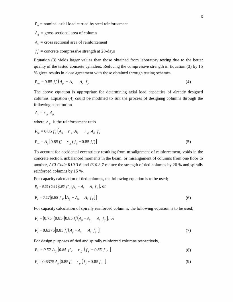
6
nsP = nominal axial load carried by steel reinforcement
gA = gross sectional area of column
sA = cross sectional area of reinforcement
cf ′ = concrete compressive strength at 28-days
Equation (3) yields larger values than those obtained from laboratory testing due to the better quality of the tested concrete cylinders. Reducing the compressive strength in Equation (3) by 15 % gives results in close agreement with those obtained through testing schemes.
( ) yssgcno fAAAfP +−′= 85.0 (4)
The above equation is appropriate for determining axial load capacities of already designed columns. Equation (4) could be modified to suit the process of designing columns through the following substitution
ggs AA ρ=
where gρ is the reinforcement ratio
( ) ygggggcno fAAAfP ρρ +−′= 85.0
[ ])85.0(85.0 cygcgno fffAP ′−+′= ρ (5)
To account for accidental eccentricity resulting from misalignment of reinforcement, voids in the concrete section, unbalanced moments in the beam, or misalignment of columns from one floor to another, ACI Code R10.3.6 and R10.3.7 reduce the strength of tied columns by 20 % and spirally reinforced columns by 15 %.
For capacity calculation of tied columns, the following equation is to be used;
( )[ ]yssgcu fAAA'f85.0)8.0(65.0P +−= , or
( )[ ]yssgcu fAAA'f85.052.0P +−= ] (6)
For capacity calculation of spirally reinforced columns, the following equation is to be used;
( ) ( )[ ( ) yssgcu fAAAfP +−′= 85.085.075.0 ], or
( )[ yssgcu fAAAfP +−′= 85.06375.0 ] (7)
For design purposes of tied and spirally reinforced columns respectively,
( )[ ]cygcgu 'f85.0f'f85.0A52.0P −+= ρ (8)
[ ( )cygcgu fffAP ′−+′= 85.085.06375.0 ρ ] (9)
7
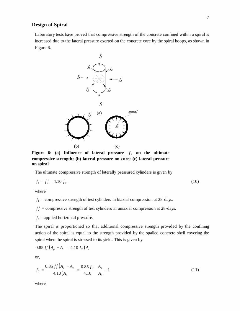
Design of Spiral
Laboratory tests have proved that compressive strength of the concrete confined within a spiral is increased due to the lateral pressure exerted on the concrete core by the spiral hoops, as shown in Figure 6.
(b) (c) Figure 6: (a) Influence of lateral pressure 2f on the ultimate compressive strength; (b) lateral pressure on core; (c) lateral pressure on spiral
The ultimate compressive strength of laterally pressured cylinders is given by
21 10.4 fff c +′= (10)
where
1f = compressive strength of test cylinders in biaxial compression at 28-days.
cf ′ = compressive strength of test cylinders in uniaxial compression at 28-days.
2f = applied horizontal pressure.
The spiral is proportioned so that additional compressive strength provided by the confining action of the spiral is equal to the strength provided by the spalled concrete shell covering the spiral when the spiral is stressed to its yield. This is given by
( ) ( )ccgc AfAAf 210.485.0 =−′
or,
( )( )
−
′=
−′= 1
10.485.0
10.485.0
2c
gc
c
cgc
AAf
AAAf
f (11)
where
(a)

8
gA = column’s gross sectional area
cA = area of concrete core based on a diameter measured out-to-out of spiral
Consider a concrete cylinder equal in depth to the pitch of the spiral S and neglect the slope of the spiral. Cutting the cylinder vertically along a diameter gives the following equilibrium equation in the horizontal direction as shown in Figure 7.
(a) (b) Figure 7: (a) Free body diagram of core and spiral cut-along a diameter; (b) one turn of spiral
22 fSDfa csys =
SDfa
fc
sys22 = (12)
where
sa = cross-sectional area of spiral
syf = yield stress of spiral
cD = core diameter = diameter minus twice the concrete cover
S = spiral’s pitch
Substituting Equation (12) into Equation (11)
( ) ( )c
c
syscgc A
SDfa
AAf210.4
85.0 =−′
SDfa
AAf
c
sys
c
gc =
−
′
120.8
85.0 (13)
letting sρ be the ratio of volume of spiral reinforcement in one turn to volume of core inside it ,
or
SDa
SDDa
c
s
c
css
4)4/( 2 ==
ππ
ρ
and 4
SDa cs
sρ
= (14)
9Substituting Equation (14) into Equation (13) gives
441
20.885.0 sys
c
sycs
c
gc fSD
fSDAAf ρρ
==
−
′
or,
−
′= 1
41.0
c
g
sy
cs A
Af
fρ (15)
The constant in the previous equation is replaced by 0.45 to get the equation given in ACI 9.10.3.
And
−
′= 1
45.0
c
g
sy
cs A
Af
fρ (16)
Combining equations (14) and (16), the pitch of the spiral S is given as
′
−
=
sy
c
c
gc
s
ff
AA
D
aS145.0
4 (17)
Columns Subjected To Pure Axial Tension
The strength under pure axial tension is computed assuming that the section is completely cracked and subjected to a uniform strain equal to, or less than yε . The axial capacity of the
concrete is ignored and the axial strength in tension is given by the following equation.
ysu fAP Φ= (18)
where Φ is the strength reduction factor for axial tension = 0.90, and sA is the area of column
reinforcement.
Design Considerations
Maximum and Minimum Reinforcement Ratios
ACI Code 10.9.1 specifies that a minimum reinforcement ratio of 1 % is to be used in tied or spirally reinforced columns. This minimum reinforcement is needed to safeguard against any bending, reduce the effect of shrinkage and creep and enhance ductility of columns. Maximum reinforcement ratio is limited to 8 % for columns in general to avoid honeycombing of concrete.
For compression member with a cross section larger than required by consideration of loading, ACI Code 10.8.4 permits the minimum area of steel reinforcement to be based on the gross sectional area required by analysis. The reduced sectional area is not to be less than one half the actual cross sectional dimensions. In regions of high seismic risk, ACI Code 10.8.4 is not applicable.

10Minimum Number of Reinforcing Bars
ACI Code 10.9.2 specifies a minimum of four bars within rectangular or circular sections; or one bar in each corner of the cross section for other shapes and a minimum of six bars in spirally reinforced columns.
Clear Distance between Reinforcing Bars
ACI Code 7.6.3 and 7.6.4 specify that for tied or spirally reinforced columns, clear distance between bars, shown in Figure 8, is not to be less than the larger of 1.50 times bar diameter or 4 cm. This is done to ensure free flow of concrete among reinforcing bars. The clear distance limitations also apply to the clear distance between lap spliced bars and adjacent lap splices since the maximum number of bars occurs at the splices.
Figure 8: Clear distance between bars
Concrete Protection Cover
ACI Code 7.7.1 specifies that for reinforced columns, the clear concrete cover is not to be taken less than 4 cm for columns not exposed to weather or in contact with ground. It is essential for protecting the reinforcement from corrosion or fire hazards.
Minimum Cross Sectional Dimensions
With the 1971 Code, minimum sizes for compression members were eliminated to allow wider utilization of reinforced concrete compression members in smaller size and lightly loaded structures, such as low-rise residential and light office buildings. When small sections are used, there is a greater need for careful workmanship. For practical considerations, column dimensions are taken as multiples of 5 cm.
Lateral Reinforcement
Ties are effective in restraining the longitudinal bars from buckling out through the surface of the column, holding the reinforcement cage together during the construction process, confining the concrete core and when columns are subjected to horizontal forces, they serve as shear reinforcement. Spirals, on the other hand, serve in addition to these benefits in compensating for the strength loss due to spalling of the outside concrete shell at ultimate column strength.

11Ties
According to ACI Code 7.10.5.1, for longitudinal bars 32 mm or smaller, lateral ties 10 mm in diameter are used. In our country and in some neighboring countries, ties 8 mm in diameter are used in column construction.
Tests have proven that spacing between ties has no significant effect on ultimate strength of columns.
ACI Code 7.10.5.2 specifies that vertical spacing of ties is not to exceed the smallest of:
§ 16 times longitudinal bar diameter.
§ 48 times tie diameter.
§ Least cross sectional dimension.
ACI Code 7.10.5.3 specifies that ties are arranged in such a way that every corner and alternate longitudinal bar is to have lateral support provided by the corner of a tie with an included angle of not more than 135 degrees. Besides, no longitudinal bar is to be farther than 15 cm clear on each side along the tie from such a laterally supported bar. When longitudinal bars are located around the perimeter of a circle, circular ties are used. Figure 9.a shows a number of tie and spiral arrangements.

12
Figure 9.a: Tie and spiral arrangements

13Spirals
According to ACI Code 7.10.4.2 spirals not less than 10 mm in diameter are to be used in cast-in-place construction. The clear pitch of the spiral is not to be less than 2.5 cm and not more than 7.5 cm as dictated by ACI Code 7.10.4.3. The smaller limit is set to ensure flow of concrete between spiral hoops while the larger limit is set to ensure effective confinement of concrete core. The diameter of the spiral could be changed to ensure that the spacing lies within the specified limits.
Bundled Bars
For isolated situations requiring heavy concentration of reinforcement, bundles of standard bar sizes can save space and reduce congestion for placement and compaction of concrete. Bundling of parallel reinforcing bars in contact is permitted but only if ties enclose such bundles. According to ACI Code 7.6.6, groups of parallel reinforcing bars bundled in contact to act as one unit are limited to four in any one bundle, as shown in Figure 9.b.
Figure 9.b: Bundled bars
Column Reinforcement Details
When column offset are necessary, longitudinal bars may be bent subject to the following limitations.
1. Slope of the inclined portion of an offset bar with axis of column must not exceed 1 in 6, shown in Figure 10.

14
Figure 10: Offset Bars
2. Portion of bar above and below the offset must be parallel to axis of column.
3. Horizontal support at offset bends must be provided by lateral ties, spirals, or parts of the floor construction. Ties or spirals, if used, shall be placed not more than 15 cm from points of bend. Horizontal support provided must be designed to resist 1.5 times the horizontal component of the computed force in the inclined portion of an offset bar.
4. Offset bars must be bent before placement in the forms.
5. When a column face is offset 7.5 cm ,or more, longitudinal column bars parallel to and near the face must not be offset bent. Separate dowels, lap spliced with the longitudinal bars adjacent to the offset column faces, must be provided as shown in Figure 11. In some cases, a column might be offset 7.5 cm or more on some faces, and less than 7.5 cm on the remaining faces, which could possibly result in some offset bent longitudinal column bars and some separate dowels being used in the same column.
Figure 11: Separated Dowels

15Column Lateral Reinforcement
Ties
In tied reinforced concrete columns, ties must be located at no more than half a tie spacing above the floor or footing and at no more than half a tie spacing below the lowest horizontal reinforcement in the slab or drop panel above. If beams or brackets frame from four directions into a column, ties may be terminated not more than 7.5 cm below the lowest horizontal reinforcement in the shallowest of such beams or brackets, shown in Figure 12.
(a) (b)
Figure 12: Beams on all column faces
Spirals
Spiral reinforcement must extend from the top of footing or slab in any story to the level of the lowest horizontal reinforcement in slabs, drop panels, or beams above. If beams or brackets do not frame into all sides of the column, ties must extend above the top of the spiral to the bottom of the slab or drop panel, shown in Figure 13.
(a) (b)
Figure 13: Beams on all column faces

16
Design Procedure for Short Axially Loaded Columns
1. Evaluate the factored axial load uP acting on the column.
2. Decide on a reinforcement ratio gρ that satisfies ACI Code limits. Usually a 1 % ratio is
chosen for economic considerations.
3. From equations (8) or (9) for tied and spirally reinforced columns respectively, determine the gross sectional area gA of the concrete section.
4. Choose the dimensions of the cross section based on its shape. For rectangular sections, the ratio of the longer to shorter side is recommended to not exceed 3.
5. Readjust the reinforcement ratio by substituting the actual cross sectional area in Equations (8) or (9). This ratio has to fall within the specified code limits.
6. Calculate the needed area of longitudinal reinforcement ratio based on the adjusted reinforced ratio and the chosen concrete dimensions.
7. From reinforcement tables, choose the number and diameters of needed reinforcing bars. For rectangular sections, a minimum of four bars is needed, while a minimum of six bars is used for circular columns.
8. Design the lateral reinforcement according to the type of column, either ties or spirals, as explained in the previous sections of this chapter.
9. Check whether the spacing between longitudinal reinforcing bars satisfies ACI Code requirements.
10. Draw the designed section showing concrete dimensions and with required longitudinal and lateral reinforcement.
Example (1):
The cross section of a short axially loaded tied column is shown in Figure 14. It is reinforced with mm166φ bars.
Calculate the design load capacity of the cross section. Use cf ′ = 280 kg/cm2 and yf = 4200
kg/cm2.
Figure 14:Column cross section

17Solution:
%21.1)25()40()100(10.12
==gρ
Clear distance between bars = ( ) ( ) ( )
cm80.122
60.1380.024240=
−−−
Since the clear distance between bars is less than 15 cm, only one tie is required for the cross section.
The spacing between ties is not to exceed the smallest of
§ 16 (1.6) = 25.60 cm
§ 48 (0.80) = 38.40 cm
§ 25 cm
φ 8 mm ties spaced @ 25 cm (one set, since only corner bars are used).
Thus, ACI requirements regarding reinforcement ratio, clear distance between bars and tie spacing are all satisfied.
Substituting in Equation (6)
( )[ ]ysSgcu fAAA'f85.052.0P +−=
( ) ( )( ) ( )[ ]420010.1210.12254028085.01000/52.0Pu +−×=
ton69.148Pu =
Example (2):
The cross section of a short axially loaded tied column is shown in Figure 14. It is reinforced with mm166φ bars.
Calculate the design tensile load capacity of the cross section. Use cf ′= 280 kg/cm2 and yf = 4200 kg/cm2.
Solution:
( ) tonsfAP ysu 74.451000420010.1290.0 =
== φ
Example (3): Design a short tied column to support a factored concentric load of 80 tons, with one side of the cross section equals to 25 cm.
Use cf ′ = 280 kg/cm2, yf = 4200 kg/cm2 and =gρ 1%.
Solution: 1- The factored load uP is given as 80 tons.

182- The reinforcement ratio gρ is given as 1%.
3- From Equation (8), determine the gross sectional area gA of the concrete section:
( )[ ]cygcgu 'f85.0f'f85.0A52.0P −+= ρ
( ) ( )[ ]28085.0420001.028085.0A52.0000,80 g ×−+=
2g cm16.554A =
4- Choose the dimensions of the cross section based on its shape:
h = 554.16/25 = 22.17 cm, use a 25 × 25 cm cross section.
5- Evaluate the adjusted gρ by substituting the newly designed gross sectional area gA in
Equation (8)
Minimum reinforcement of 1 % will be used.
6- Calculate the needed area of longitudinal reinforcement ratio:
gas AA ρ= = 0.01 (554.16) = 5.54 cm2
7- From reinforcement tables, choose the number and diameters of needed reinforcement: use ( )216.6144 cmAmm s =φ
8- Design the needed ties:
The spacing between ties is not to exceed the smallest of
§ 16 (1.4) = 22.40 cm
§ 48 (0.80) = 38.40 cm
§ 20 cm
Use ties φ 8 mm spaced @ 20 cm (one set, since only corner bars are used).
9- Check whether the spacing between longitudinal reinforcing bars satisfies ACI Code requirements:
( ) ( ) ( ) ( ) cm0.4cm40.15.1cm6.1240.1280.024225Sclear >>=−−−=
10- The designed cross section together with needed longitudinal and lateral reinforcement is shown in Figure 15.

19
Figure 15: Designed cross section
Example (4): Design a short, spirally reinforced column to support a service dead load of 45 tons and a service live load of 60 tons.
Use cf ′ = 280 kg/cm2, yf = 4200 kg/cm2.and =gρ 1%.
Solution: 1- LDu P60.1P20.1P += = 1.20 (45) + 1.6 (60) = 150 tons
2- The reinforcement ratio gρ is given as 1%.
3- From equation (10.19.b), determine the gross sectional area gA of the concrete section:
[ ])85.0(85.06375.0 cygcgu fffAP ′−+′= ρ ( ) ( )[ ]28085.0420001.028085.0A6375.0000,150 g ×−+=
2g cm54.847A =
4- Choose the dimensions of the cross section based on its shape:
D = 32.85 cm, taken as 35 cm in diameter.
5- gρ is taken as 1 % since smaller values are not allowed by the code.
6- Calculate the needed area of longitudinal reinforcement ratio:
== ggs AA ρ ( )( ) 22 cm62.9354/01.0 =π
7- From reinforcement tables, choose the number and diameters of needed reinforcement: use )cm78.10A(mm147 2
s =φ
8- Design the needed spiral:
From Equation (16) and trying φ 8 mm spiral,
cmDc 274435 =−−=

20
′
−
=
sy
c
c
gc
s
ff
AA
D
aS
145.0
4
( )
( ) ( )( )( )( )
cmS 63.3
42002801
274/354/
2745.0
50.04
2
2=
−
=
π
π
taken as 3.50 cm (center-to-center)
cmSc 7.280.05.3 =−= , i.e within ACI Code limits.
Use φ 8 mm spiral with a pitch of 3.5 cm, center-to-center.
9- Check whether the spacing between longitudinal reinforcing bars satisfies ACI Code requirements:
D′ = 35 – 2 (4) –2 (0.80) –1.40 = 24 cm
S = 2 (12)
2
43.51sino
= 10.41 cm
( ) cmcmcmSclear 0.440.15.101.940.141.10 >>=−=
10- The designed cross section together with needed longitudinal and lateral reinforcement is shown in Figure 16.
Figure 16: Designed cross section