Embed Size (px)
Citation preview
A PRESENTION ON THE DESIGN OF AN OFFICE BUILDING
Design of Structural Systems CIE-600
By Kalpesh P.
General information about the building Design of Slabs Design of Beams, columns and Foundation Design of shear and retaining walls Design of Stair case Green Engineering and Aesthetics Aspect Material (concrete) Usage Estimation References
Presentation Outline
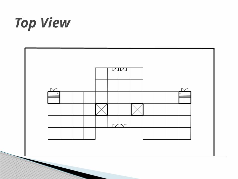
Building◦ An office building◦ Located in Syracuse ◦ A three-story of 58 ft high building◦ Has three buildings separated by an expansion
joint◦ Two freight, Two passenger elevators◦ Two stair cases
Retaining wall – Height of 10 ft Materials used
◦ Concrete -6000psi and Steel-60000psi ACI and International building codes
adopted
General Information
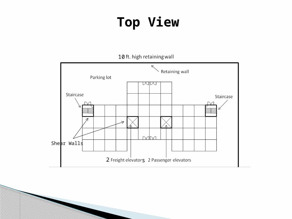
Top View
Shear Walls
10
2 s

Views of the building
16’
26’
16’
25’ 25’ 25’ 25’
25’25’25’
25’25’
25’25’
25’
Flat PlateFlat Slab
Slab with beams
Slab on ground25’25’
25’25’
Parapet 1’
Staircase
Staircase
2 Freight elevators2 Passenger elevators

2. Slabs Design Flat plate
Flat Slab
Slab with interior beam
Slab on Ground

Location of Design Slabs
16’
26’
16’
25’ 25’ 25’ 25’
25’25’25’
25’25’
25’25’
25’
Flat PlateFlat Slab
Slab with beams
Slab on ground
25’25’25’ 25’
Top View
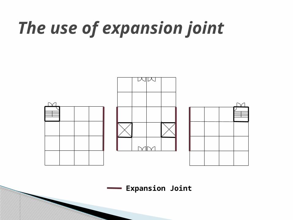
The use of expansion joint
Expansion Joint
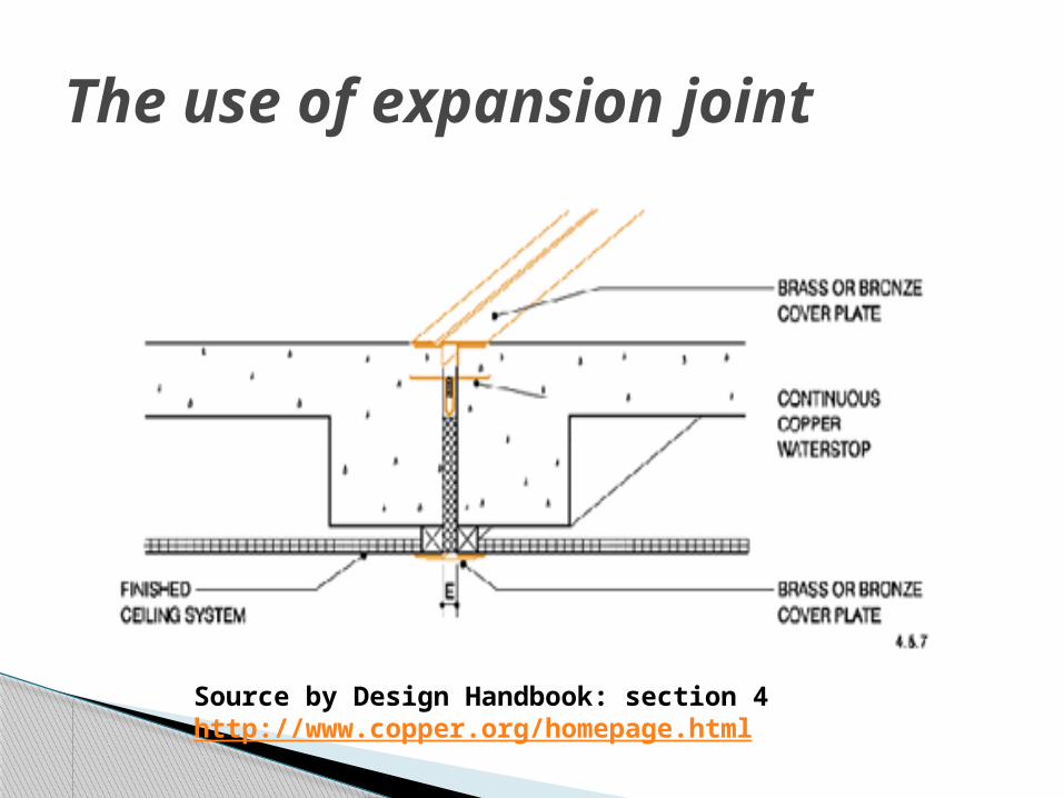
The use of expansion joint
Source by Design Handbook: section 4http://www.copper.org/homepage.html
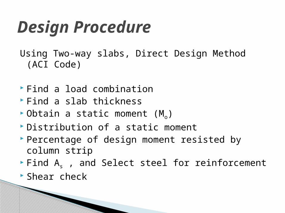
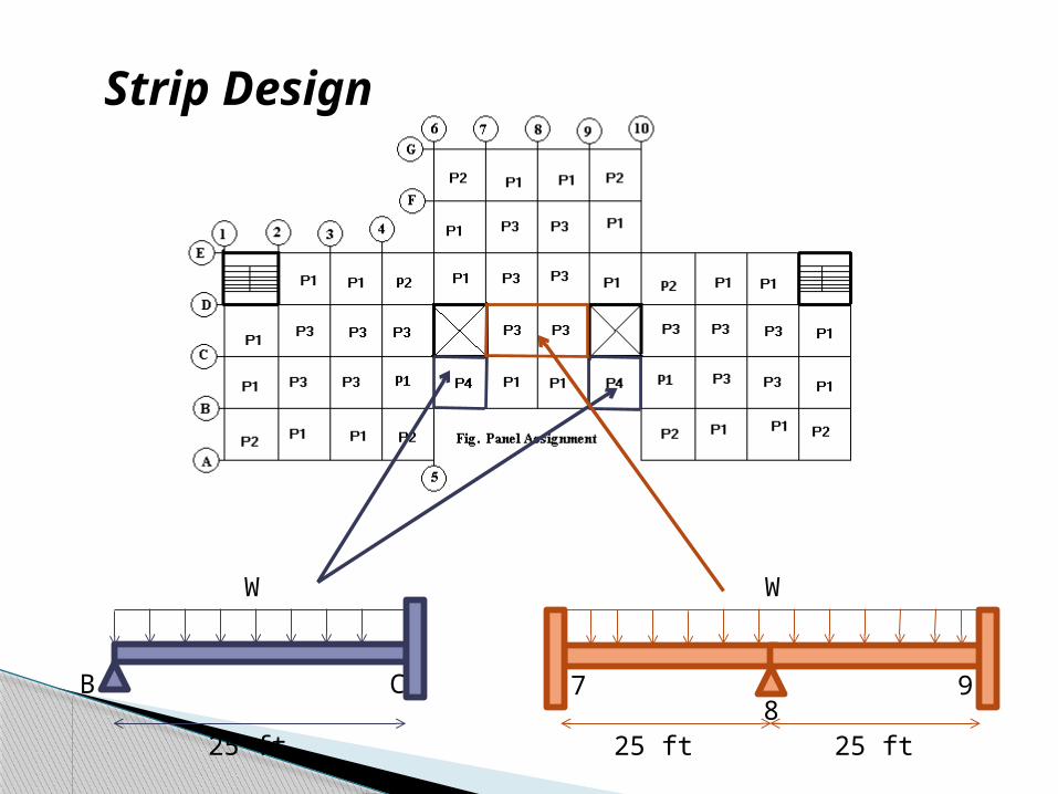
Design ProcedureUsing Two-way slabs, Direct Design Method (ACI
Code)
Find a load combination Find a slab thickness Obtain a static moment (Mo) Distribution of a static moment Percentage of design moment resisted by column
strip Find As , and Select steel for reinforcement Shear check
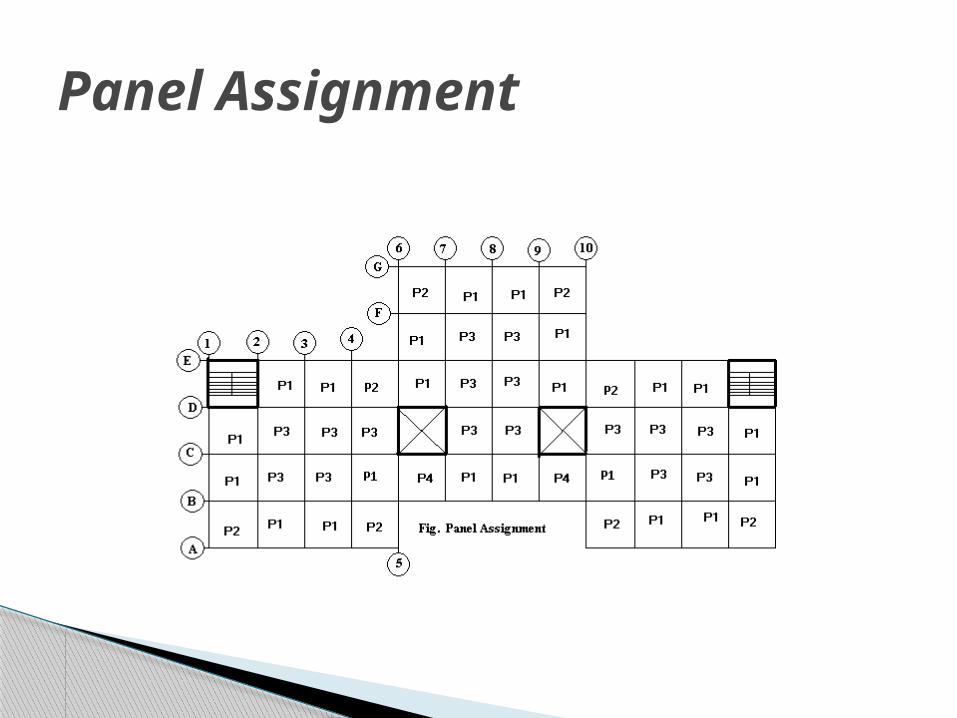
Panel Assignment
B C
W
25 ft
W
78
9
25 ft 25 ft
Strip Design

Combination Loads
U = 1.2(D + F + T) + 1.6(L + H) + 0.5(Lr or S or R)
Dead load (D) = 150 psf x thickness of slabTopping load (T) = 20 psfLive load (LL) = 50 psfFinishing load (F) = 20 psfRain load (R) = 62.5 psfSnow load (S) = 46.2 psfRoof live load(Lr) = 12.0 psf

Design Numerical Values
Types of Slab Flat Plate Flat Slab Slab with Beams
Slab Thickness
9” 8” 7”
Load combination
(U)
226.25 psf
224 psf 203 psf
Static Moment (Mo)
401.61 ft-k
397.62 ft-k 370.90 ft-k
CT1
CT1
y
CT1
y
CT1
y
MB
MB
MB
MB
MB
MB
MB
MB
MB
MB
MB
MB
MB
MB
MB
MB
CTy
CT2
y
CT2
y
CT2
yC
Ty
CTy
CTy
CTy
CT2 CT
CT2CT CT
CTC
By
CB
y
CB
y
CB
y
CB
y
CB
y
CB
1y
CB
1yC
B1y
CB
CB
CB
CB
CB1
CB1CB1
CTCB1
CB
1y
CB
1y
CB1
MT
MT
MT
MT
MT
MT
MT
MT
MT
MT
MT
MT
MB
MB
MB
MB
MB
MB
MB
MBMT MT MT
MT
MB
MB
MB
MB
MB
MBMTMTMT1
MT1
CT2
CT1
CT1
CT1
CT1
CT2 CTCB CB CB1
CT2C
T2
CT1
y
MT1
CT2
MT1
MT1
MT1
MT1
MT1
MT1
CT1
MT1
CTy
CB
yC
T2y
CB
yC
TyC
B1y
CB
1y
CT1
CTy
CB
yC
T2y
CB
yC
T2y
CB
1y
CB
1y
CT3CT2CT3CB2 CB2 CB1CB3
CTCT2CB CB CB1CT2
MT1
MT1
MT1
MT1
MT1
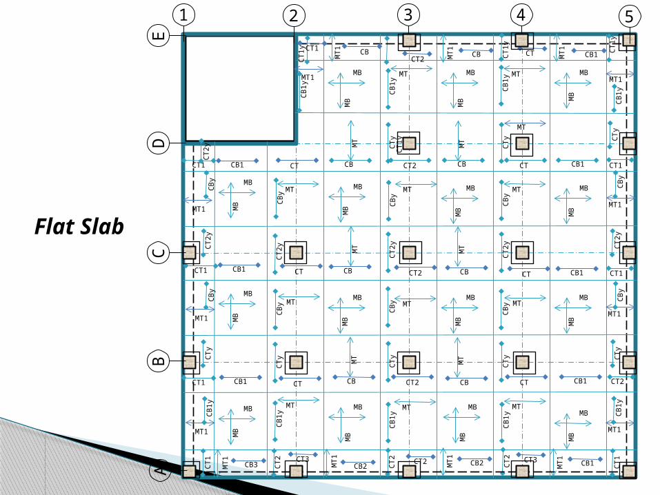
1 2 3 4 5
EC
DA
B
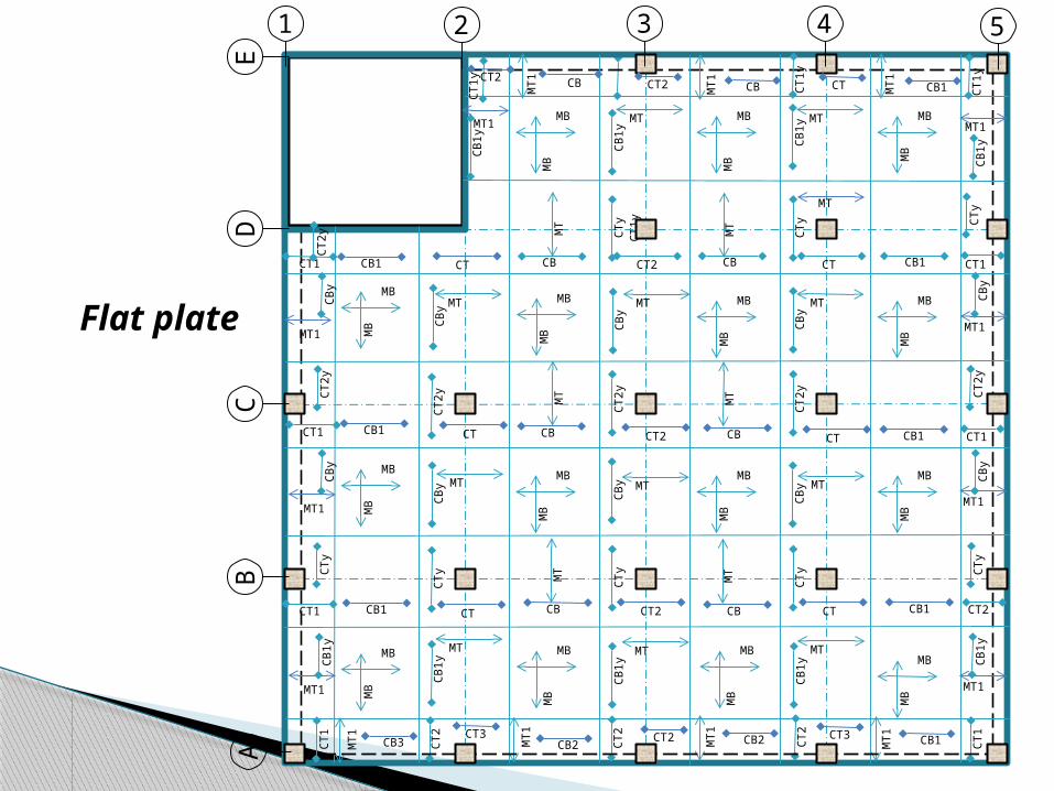
Flat plate
MT1
MT1
CT1
CT1
y
MB
MB
MB
MB
MB
MB
MB
MB
MB
MB
MB
MB
MB
MB
MB
MB
CTy
CT2
y
CT2
y
CT2
yC
Ty
CT2
yC
Ty
CTy
CT2 CT
CT2CT CT
CT
CB
y
CB
y
CB
y
CB
y
CB
y
CB
y
CB
1y
CB
1yC
B1y
CB
CB
CB
CB
CB1
CB1CB1
CTCB1
CB
C1y
CB
1y
CB1
MT
MT
MT
MTC
MT
MT
MT
MT
MT
MT
MT
MT
MT
MB
MB
MB
MB
MB
MBM
BMB
MT MT MT
MB
MB
MB
MB
MB
MBMTMTMT1
MT1
CT1
y
CT1
CT1
CT1
CT1
CT2 CTCB CB1
CT1
CT1
y
CT1
y
MT1
MT1
MT1
MT1
MT1
MT1
CT1
y
MT1
CTy
CB
yC
T2y
CB
yC
TyC
B1y
CB
1y
CTc
yC
TyC
By
CT2
yC
By
CT2
yC
BC
y
CB
1y
CTCT2CTCB CB CB1CB1 M
T1
MT1
MT1
FD
EB
C
v
M B
MB
MB
MB
MB
MB
MB
MB
MT
MT
CB1CB1
MT
CBCB
MT
MT
MT MT
CB
1y
CB
1y
CB
1y
MT
C B
1y
MT1
CB
y
MT1
CB1 CB1CBCB
MT1
MT1
CB
MTMT
MB
MB
CT
CTy
CTy
CTy
CT2
CT2
y CT
MT1
C B
1y
CT CT
CTC
CT2 MT1
MB
MB
MB
MB
CT
CTC
6 7 8 9 10
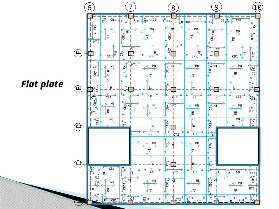
Flat plate

MTC is the same as MT but with bar #5 c/c 13.5 in CTCY is the same as CT1Y but with bar #4 c/c 12 inCTC is the same as CTY but with bar # 5 c/c 10 in CBC1Y is the same as CB1Y but with bar # 5 c/c 16 in
Flat plateType Strip Placed
@Specification
Bar No. Spacing (in), Length and type
CT column top 5
CT1 column top 5
CT2 column top 5
CTY column top 5
CT1Y column top 5
CT2Y column top 5
CB column bottom 4
CB1 column bottom 5
CBY column bottom 4
CB1Y column bottom 5
MB middle bottom 4
MT middle top 4
MT1 middle top 4
L= 15.4ft c/c 15 inL= 10.6 ft c/c 15 in
L= 9.5 ft c/c 13 inL= 7.2 ft c/c 13 in
L= 15.4 ft c/c 16inL=10.6 ft c/c 16in
L= 15.4 ft c/c 14inL=10.6 ft c/c 14in
L= 15.4 ft c/c 15inL=10.6 ft c/c 15in
L= 7.5 ft c/c 12 in
L= 25ft c/c 12 in
L= 25ft c/c 20 inL= 26.5ft c/c 20 in
L= 25ft c/c 11.5 in
L= 25ft c/c 21 inL= 26.5ft c/c 21 in
L= 12 ft c/c 12in
L= 25.5ft c/c 24 inL= 17ft c/c 24 in
L= 9.5 ft c/c 12inL= 7.2 ft c/c 12 in
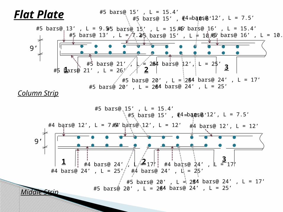
#4 bars@ 12’, L = 7.5’
#4 bars@ 24’ , L = 17’#4 bars@ 24’ , L = 25’
#4 bars@ 24’ , L = 17’#4 bars@ 24’ , L = 25’
#4 bars@ 12’, L = 12’#4 bars@ 12’, L = 12’
#5 bars@ 15’ , L = 15.4’ #5 bars@ 15’ , L = 10.6’#4 bars@ 12’, L = 7.5’
#5 bars@ 20’ , L = 25’#5 bars@ 20’ , L = 26’
#4 bars@ 24’ , L = 17’#4 bars@ 24’ , L = 25’
#5 bars@ 13’ , L = 9.5’ #5 bars@ 13’ , L = 7.2’
#4 bars@ 12’, L = 25’
#5 bars@ 15’ , L = 15.4’ #5 bars@ 15’ , L = 10.6’
#5 bars@ 16’ , L = 15.4’ #5 bars@ 16’ , L = 10.6’
#5 bars@ 21’ , L = 25’#5 bars@ 21’ , L = 26’
#5 bars@ 20’ , L = 25’#5 bars@ 20’ , L = 26’
#4 bars@ 24’ , L = 17’#4 bars@ 24’ , L = 25’
#5 bars@ 15’ , L = 15.4’ #5 bars@ 15’ , L = 10.6’#4 bars@ 12’, L = 7.5’
9’
1 2 3
1 2 3
9’
Column Strip
Middle Strip
Flat Plate
CT1
CT1
y
CT1
y
CT1
y
MB
MB
MB
MB
MB
MB
MB
MB
MB
MB
MB
MB
MB
MB
MB
MB
CTy
CT2
y
CT2
y
CT2
yC
Ty
CTy
CTy
CTy
CT2 CT
CT2CT CT
CTC
By
CB
y
CB
y
CB
y
CB
y
CB
y
CB
1y
CB
1yC
B1y
CB
CB
CB
CB
CB1
CB1CB1
CTCB1
CB
1y
CB
1y
CB1
MT
MT
MT
MT
MT
MT
MT
MT
MT
MT
MT
MT
MB
MB
MB
MB
MB
MB
MB
MBMT MT MT
MT
MB
MB
MB
MB
MB
MBMTMTMT1
MT1
CT2
CT1
CT1
CT1
CT1
CT2 CTCB CB CB1
CT2C
T2
CT1
y
MT1
CT2
MT1
MT1
MT1
MT1
MT1
MT1
CT1
MT1
CTy
CB
yC
T2y
CB
yC
TyC
B1y
CB
1y
CT1
CTy
CB
yC
T2y
CB
yC
T2y
CB
1y
CB
1y
CT3CT2CT3CB2 CB2 CB1CB3
CTCT2
CB CB CB1CT1
MT1
MT1
MT1
MT1
MT1
1 2 3 4 5
EC
DA
B
Flat Slab
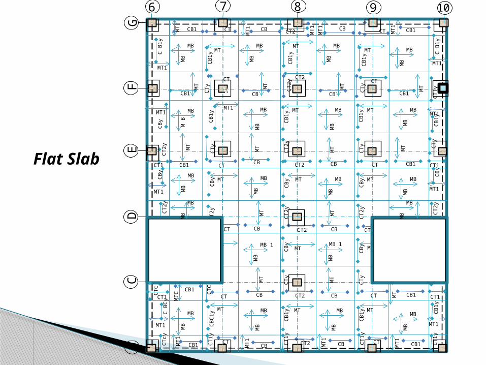
G
6 7 8 9 10
MT1
MT1
CT1
CT1
y
MB
MB 1
MB
MB 1
MB
MB
MB
MB
MB
MB
MB
MB
MB
MB
MB
MB
CTy
CT2
y
CT2
y
CT2
yC
Ty
CT2
yC
Ty
CTy
CT2 CT
CT2CT CT
CT
CB
y
CB
y
CB
y
CB
y
CB
y
CB
y
CB
1y
CB
1yC
B1y
CB
CB
CB
CB
CB1
CB1CB1
CTCB1
CB
C1y
CB
1y
CB1
MT
MT
MT
MTC
MT
MT
MT
MT
MT
MT
MT
MT
MT
MB
MB
MB
MB
MB
MBM
BMB
MT MT MT
MB
MB
MB
MB
MB
MBMTMTMT1
MT1
CT1
y
CT1
CT1
CT1
CT1
CT2 CTCB CB1
CT1
CT1
y
CT1
y
MT1
MT1
MT1
MT1
MT1
MT1
CT1
y
MT1
CTy
CB
yC
T2y
CB
yC
TyC
B1y
CB
1y
CTc
yC
TyC
By
CT2
yC
By
CT2
yC
BC
y
CB
1y
CTCT2CTCB CB CB1CB1 M
T1
MT1
MT1
FD
EB
C
v
M B
MB
MB
MB
MB
MB
MB
MB
MT
MT
CB1CB1
MT
CBCB
MT
MT
MT MT
CB
1y
CB
1y
CB
1y
MT
C B
1y
MT1
CB
y
MT1
CB1 CB1CBCB
MT1
MT1
CB
MTMT
MB
MB
CT
CTy
CTy
CTy
CT2
CT2
y CT
MT1
C B
1y
CT CT
CTC
CT2 MT1
MB
MB
MB
MB
CT
CTC
Flat Slab
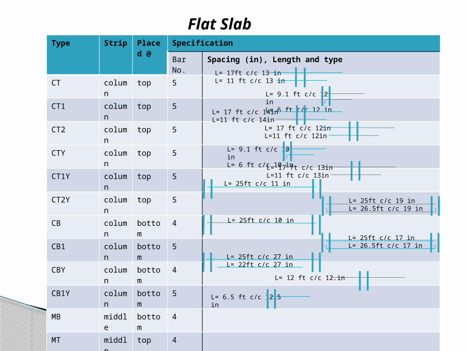
MTC is the same as MT but with bar #5 c/c 13.5 in CBC1Y is the same as CB1Y but with bar # 5 c/c 16 inCTC is the same as CTY but with bar # 5 c/c 10 in MB1 is the same as MB but with bar #4 c/c 24 inCTCY is the same as CT1Y but with bar #4 c/c 12 in
Flat SlabType Strip Placed
@Specification
Bar No. Spacing (in), Length and type
CT column top 5
CT1 column top 5
CT2 column top 5
CTY column top 5
CT1Y column top 5
CT2Y column top 5
CB column bottom 4
CB1 column bottom 5
CBY column bottom 4
CB1Y column bottom 5
MB middle bottom 4
MT middle top 4
MT1 middle top 4
L= 17ft c/c 13 inL= 11 ft c/c 13 in
L= 9.1 ft c/c 12 inL= 6 ft c/c 12 in
L= 17 ft c/c 14inL=11 ft c/c 14in
L= 17 ft c/c 12inL=11 ft c/c 12in
L= 17 ft c/c 13inL=11 ft c/c 13in
L= 6.5 ft c/c 12.5 in
L= 25ft c/c 11 in
L= 25ft c/c 17 inL= 26.5ft c/c 17 in
L= 25ft c/c 10 in
L= 25ft c/c 19 inL= 26.5ft c/c 19 in
L= 12 ft c/c 12.in
L= 25ft c/c 27 inL= 22ft c/c 27 in
L= 9.1 ft c/c 10 inL= 6 ft c/c 10 in
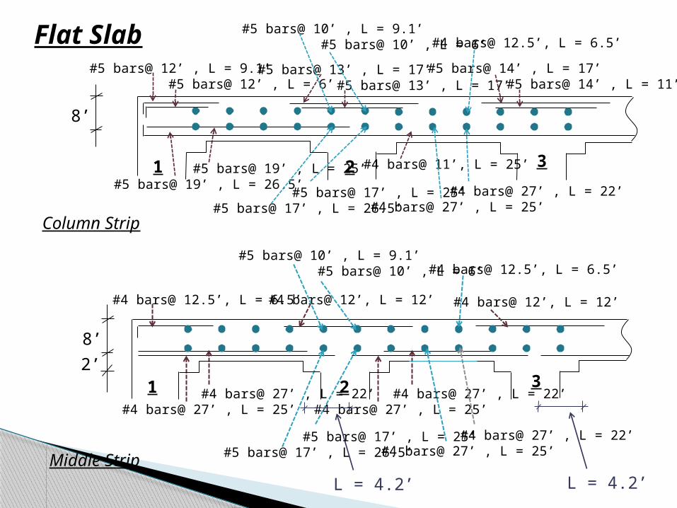
#4 bars@ 12.5’, L = 6.5’
#4 bars@ 27’ , L = 22’#4 bars@ 27’ , L = 25’
#4 bars@ 27’ , L = 22’#4 bars@ 27’ , L = 25’
#4 bars@ 12’, L = 12’#4 bars@ 12’, L = 12’
#5 bars@ 12’ , L = 9.1’ #5 bars@ 12’ , L = 6’
#4 bars@ 11’, L = 25’
#5 bars@ 13’ , L = 17’ #5 bars@ 13’ , L = 17’
#5 bars@ 14’ , L = 17’ #5 bars@ 14’ , L = 11’
#5 bars@ 19’ , L = 25’#5 bars@ 19’ , L = 26.5’ #5 bars@ 17’ , L = 25’
#5 bars@ 17’ , L = 26.5’ #4 bars@ 27’ , L = 22’#4 bars@ 27’ , L = 25’
#5 bars@ 10’ , L = 9.1’ #5 bars@ 10’ , L = 6’ #4 bars@ 12.5’, L = 6.5’
8’
1 2 3
1 2 3
8’
Column Strip
Middle Strip
Flat Slab
2’
L = 4.2’L = 4.2’
#5 bars@ 10’ , L = 9.1’ #5 bars@ 10’ , L = 6’ #4 bars@ 12.5’, L = 6.5’
#5 bars@ 17’ , L = 25’#5 bars@ 17’ , L = 26.5’
#4 bars@ 27’ , L = 22’#4 bars@ 27’ , L = 25’

CT1
CT1
CT1
CT1
MB
MB
MB
MB
MB
MB1
MB
1
MB
MB
1
MB
MB
MB1
MB
1
MB1
MB
1
MB1
CT
CT CT
CT
CT
CTy
CT CT
CT CT
CTCT CT
CTC
By
CB
CB
CB
CB CB
CB
1
CB
1C
B1
CB
CB
CB
CB
CB1
CB1CB1
CTCB1
CB
1
CB
1
CB1
MT
MT
MT
MT
MT
MT
MT
MT
MT
MT
MT
MT
MB
MB
MB
MB1
MB
MB
MB
MB1MT MT MT
MT
MB
1
MB
MB
1
MB
MB
1
MB1MTMTMT1
MT1
CT1
CT1
CT1
CT1
CT1
CT CTCB CB CB1
CT1C
T1
CT1 M
T1
CT1
MT1
MT1
MT1
MT1
MT1
MT1
CT1
MT1
CT
CB
CT
CB
CT
CB
1C
B1
CT1
CT
CB
CT
CB
yC
TC
B1
CB
1
CTCTCTCB CB CB1CB1
CTCT2CB CB CB1CT2
MT1
MT1
MT1
MT1
MT1
1 2 3 4 5
EC
DA
B
Slab with Beams
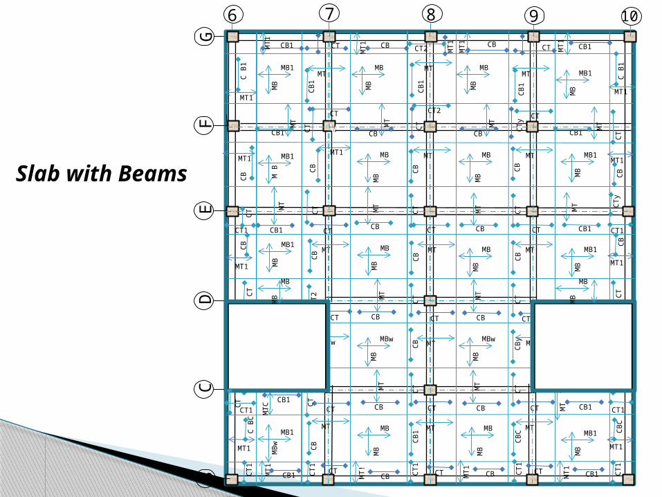
G
6 7 8 9 10
MT1
MT1
CT1
CT
MB
MBw
MB
MBw
MB
MB
MB
MB
MB
MB
MB
MB
MB
MB1
MB
MB1
CTy
CT2 CT
CT
CT
CT
CT
CT
CT CT
CTCT CT
CTC
By
CB
CB
y
CB
CB CB
CB CB
CB
C
CB
CB
CB
CB
CB1
CB1CB1
CTCB1
CB C
B1
CB1
MT
MT
MT
MTC
MT
MT
MT
MT
MT
MTw
MT
MT
MT
MB
MB
MB
MB1
MB
MB
MB
MB1MT MT MT
MB
MB
MB
MB
MB
MB1MTMTMT1
MT1
CT1
CT1
CT1
CT1
CT1
CT CTCB CB1
CT1
CT1 CT1
MT1
MT1
MT1
MT1
MT1
MT1
CT1
MT1
CTy
CB
yC
TC
BC
TyC
BC
CB
CT1
CTy
CB
yC
TC
BC
TC
BC
CB
CTCTCTCB CB CB1CB1 M
T1
MT!
MT1
FD
EB
C
v
M B
MB1
MB
MB
MB
MB
MB
MB1
MT
MT
CB1CB1
MT
CBCB
MT
MT
MT MT
CB
1
CB
1
CB
1
MT
C B
1
MT1
CB
MT1
CB1 CB1CBCB
MT1
MT1
CB
MTMT
MB
w
MB1
CT
CT
CT
CTy
CT2
CT
CT
MT1
C B
1
CT CT
CT
CT2 MT1
MB
MB
MB
MB
CT
CT
Slab with Beams
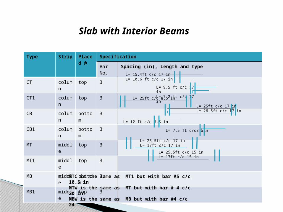
Type Strip Placed @
Specification
Bar No. Spacing (in), Length and type
CT column top 3
CT1 column top 3
CB column bottom 3
CB1 column bottom 3
MT middle top 3
MT1 middle top 3
MB middle bottom 3
MB1 middle top 3
L= 15.4ft c/c 17 inL= 10.6 ft c/c 17 in
L= 9.5 ft c/c 17 inL= 7.2 ft c/c 17 in
L= 7.5 ft c/c8.5in
L= 25ft c/c 8.5 in
L= 25ft c/c 17 inL= 26.5ft c/c 17 in
L= 12 ft c/c 6.5 in
L= 25.5ft c/c 17 inL= 17ft c/c 17 in
L= 25.5ft c/c 15 inL= 17ft c/c 15 in
MTC is the same as MT1 but with bar #5 c/c 10.5 inMTW is the same as MT but with bar # 4 c/c 20 inMBW is the same as MB but with bar #4 c/c 24
Slab with Interior Beams
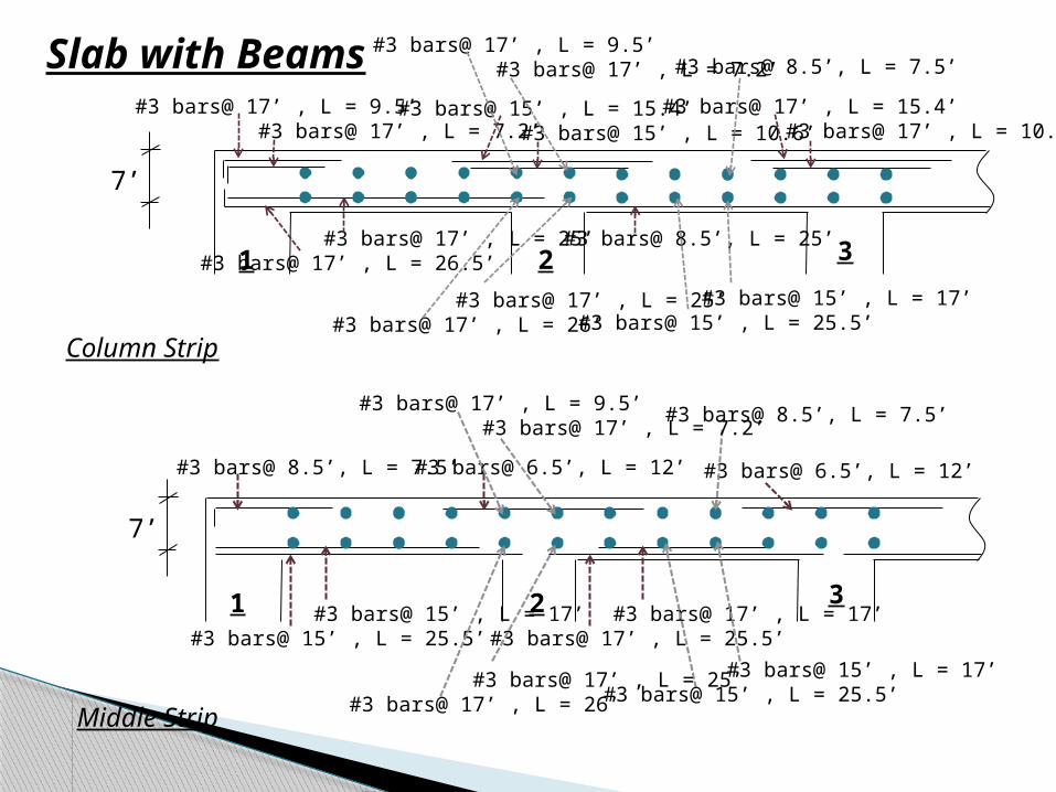
#3 bars@ 8.5’, L = 7.5’
#3 bars@ 17’ , L = 17’#3 bars@ 17’ , L = 25.5’
#3 bars@ 15’ , L = 17’#3 bars@ 15’ , L = 25.5’
#3 bars@ 6.5’, L = 12’#3 bars@ 6.5’, L = 12’
#3 bars@ 17’ , L = 9.5’ #3 bars@ 17’ , L = 7.2’
#3 bars@ 8.5’, L = 25’
#3 bars@ 15’ , L = 15.4’ #3 bars@ 15’ , L = 10.6’
#3 bars@ 17’ , L = 15.4’ #3 bars@ 17’ , L = 10.6’
#3 bars@ 17’ , L = 25’#3 bars@ 17’ , L = 26.5’
#3 bars@ 17’ , L = 25’#3 bars@ 17’ , L = 26’
#3 bars@ 15’ , L = 17’#3 bars@ 15’ , L = 25.5’
#3 bars@ 17’ , L = 9.5’ #3 bars@ 17’ , L = 7.2’ #3 bars@ 8.5’, L = 7.5’
7’
1 2 3
1 2 3
7’
Column Strip
Middle Strip
Slab with Beams
#3 bars@ 17’ , L = 9.5’ #3 bars@ 17’ , L = 7.2’
#3 bars@ 8.5’, L = 7.5’
#3 bars@ 17’ , L = 25’#3 bars@ 17’ , L = 26’
#3 bars@ 15’ , L = 17’#3 bars@ 15’ , L = 25.5’
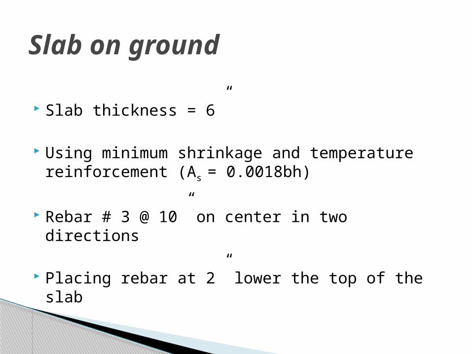
Slab on ground
Slab thickness = 6”
Using minimum shrinkage and temperature reinforcement (As = 0.0018bh)
Rebar # 3 @ 10” on center in two directions
Placing rebar at 2” lower the top of the slab
• Beams• Edge beams • Interior Beams
• Columns • Column at a corner• Exterior Columns• Interior columns
• Footing• Footing under a corner column• Footing under an edge column• Footing under an interior column• Common footing
Design of Beams,Columns and Footings
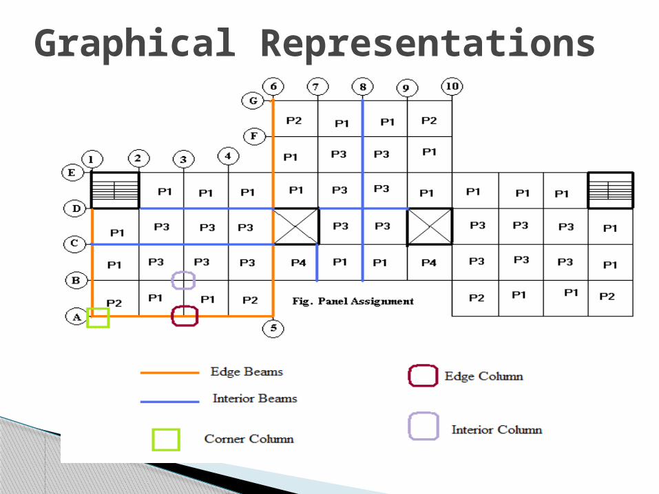
Graphical Representations
Loading on beams: Depends on their location in a floor and along a story
The loads may include Loads from Slabs Self weight of beams Weight of walls or attachments that directly lie
or attached on the beams Parapet Walls Curtain walls Partition walls
Beam Design

Load Transfer to beams
Load transfer from slabsLoad transfer from curtain walls slabs

Summary of Loading on Edge Beams
Floor level
Factored Design loadsDue to parapet wallUdl- k/ft
Due to self weight of beam stem/webUdl- k/ft
Due to glass curtain wallsUdl – k/ft
Weight from slabs ( triangular) w (k/ft)
Flat plate 0.09 0.11 0.072 2.82Flat slab 0 0.125 0.144 2.79Floor with beams
0 0.141 0.189 2.61
Grade beams
0 0.251 0.117 0
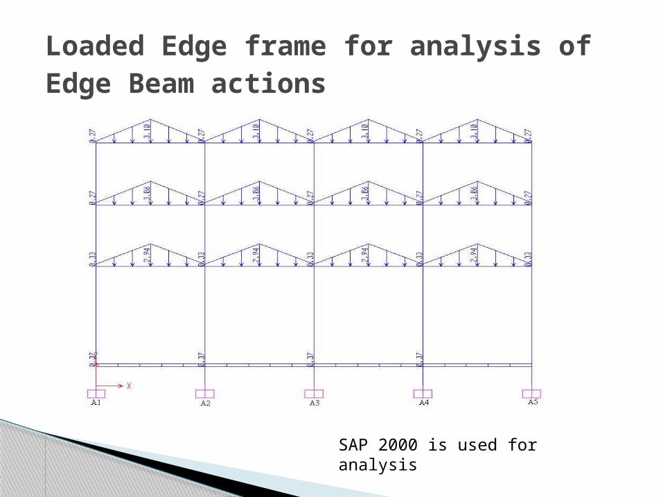
Loaded Edge frame for analysis of Edge Beam actions
SAP 2000 is used for analysis

Loaded frame for analysis of Interior Beam actions
Loading diagram (axis 1B-2B-3B-4B-5B) for the purpose of calculating additional moments due to self weight of beam
Loading diagram (axis 1B-2B-3B-4B-5B) for the purpose of calculating shear in internal beams due to loads from slab
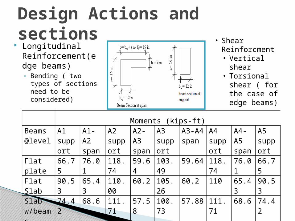
Longitudinal Reinforcement(edge beams)◦ Bending ( two types
of sections need to be considered)
Design Actions and sections
Moments (kips-ft)Beams @level
A1support
A1-A2span
A2support
A2-A3span
A3support
A3-A4span
A4support
A4-A5span
A5support
Flat plate 66.75 76.01 118.74 59.64 103.49 59.64 118.74 76.01 66.75Flat Slab 90.53 65.43 110.00 60.2 105.26 60.2 110 65.43 90.53Slab w/beams
74.42 68.6 111.71 57.58 100.73 57.88 111.71 68.6 74.42
Ground 18.21 9.77 19.5 9.45 19.29 9.45 19.5 9.77 18.21
• Shear Reinforcment • Vertical shear• Torsional shear
( for the case of edge beams)
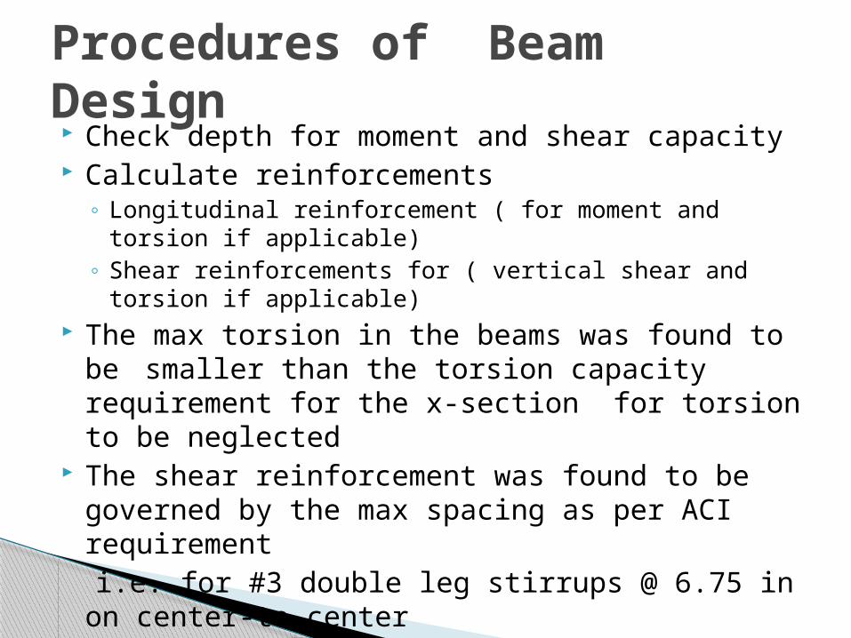
Check depth for moment and shear capacity Calculate reinforcements
◦ Longitudinal reinforcement ( for moment and torsion if applicable)
◦ Shear reinforcements for ( vertical shear and torsion if applicable)
The max torsion in the beams was found to be smaller than the torsion capacity requirement for the x-section for torsion to be neglected
The shear reinforcement was found to be governed by the max spacing as per ACI requirement
i.e. for #3 double leg stirrups @ 6.75 in on center-to-center
Procedures of Beam Design
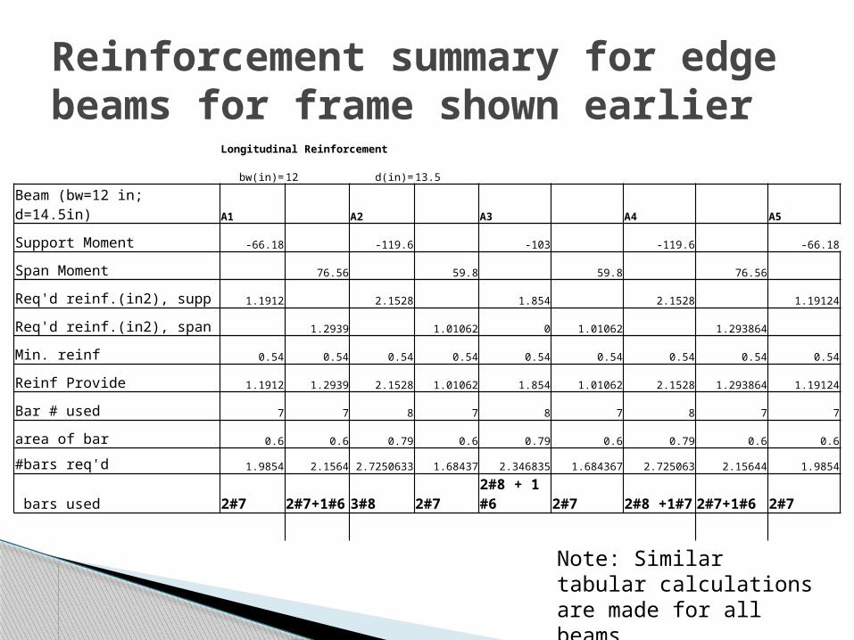
Reinforcement summary for edge beams for frame shown earlier
Longitudinal Reinforcement
bw(in)=12 d(in)= 13.5
Beam (bw=12 in; d=14.5in) A1 A2 A3 A4 A5
Support Moment -66.18 -119.6 -103 -119.6 -66.18
Span Moment 76.56 59.8 59.8 76.56
Req'd reinf.(in2), supp 1.1912 2.1528 1.854 2.1528 1.19124
Req'd reinf.(in2), span 1.2939 1.01062 0 1.01062 1.293864
Min. reinf 0.54 0.54 0.54 0.54 0.54 0.54 0.54 0.54 0.54
Reinf Provide 1.1912 1.2939 2.1528 1.01062 1.854 1.01062 2.1528 1.293864 1.19124
Bar # used 7 7 8 7 8 7 8 7 7
area of bar 0.6 0.6 0.79 0.6 0.79 0.6 0.79 0.6 0.6
#bars req'd 1.9854 2.1564 2.7250633 1.68437 2.346835 1.684367 2.725063 2.15644 1.9854
bars used 2#7 2#7+1#6 3#8 2#7 2#8 + 1 #6 2#7 2#8 +1#7 2#7+1#6 2#7
Note: Similar tabular calculations are made for all beams

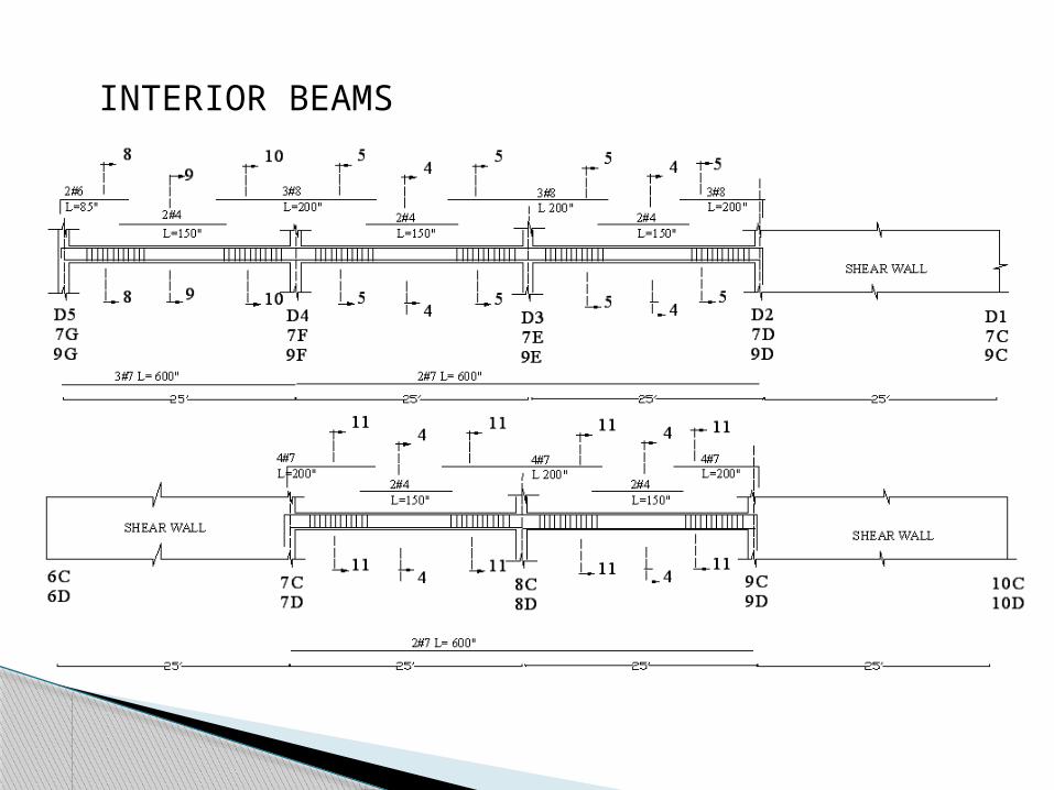
INTERIOR BEAMS

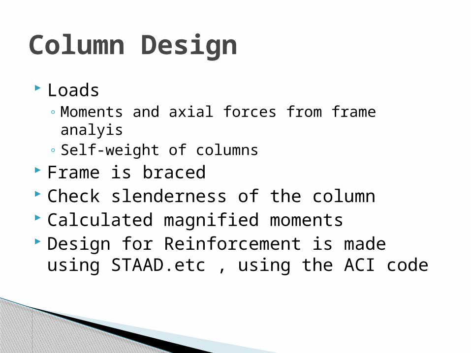
Loads ◦ Moments and axial forces from frame analyis◦ Self-weight of columns
Frame is braced Check slenderness of the column Calculated magnified moments Design for Reinforcement is made using
STAAD.etc , using the ACI code
Column Design
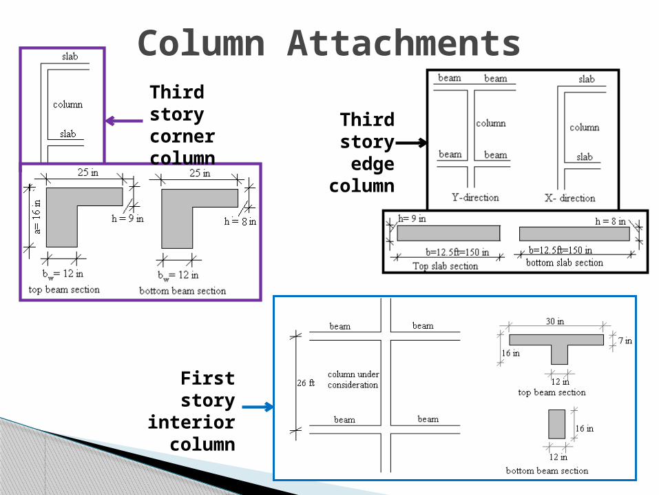
Column AttachmentsThird story corner column
Third story edge
column
First story interior column
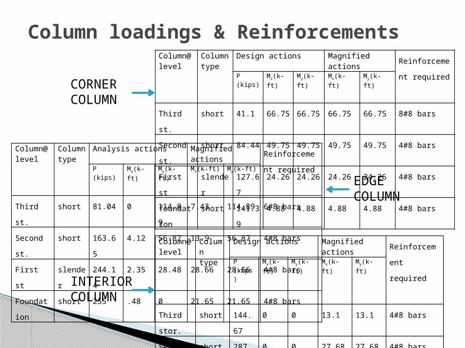
Column loadings & Reinforcements Column@ level
Column type
Design actions Magnified actions Reinforcement
requiredP (kips) Mx(k-ft) My(k-ft) Mx(k-ft) My(k-ft)
Third st. short 41.1 66.75 66.75 66.75 66.75 8#8 bars
Second st. short 84.44 49.75 49.75 49.75 49.75 4#8 bars
First st slender 127.67 24.26 24.26 24.26 24.26 4#8 bars
foundation short 141.39 4.88 4.88 4.88 4.88 4#8 barsColumn@ level
Column type
Analysis actions Magnified actions Reinforcement
requiredP (kips) Mx(k-ft) My(k-ft) Mx(k-ft) My(k-ft)
Third st. short 81.04 0 114.89 7.43 114.89 6#8 bars
Second st. short 163.65 4.12 56.87 13.9 56.87 4#8 bars
First st slender 244.14 2.35 28.48 28.66 28.66 4#8 bars
Foundation short 255 .48 0 21.65 21.65 4#8 barsColumn@ level
Column type
Design actions Magnified actions Reinforcement
requiredP (kips) Mx(k-ft) My(k-ft) Mx(k-ft) My(k-ft)
Third stor. short 144.67 0 0 13.1 13.1 4#8 bars
Second st. short 287.93 0 0 27.68 27.68 4#8 bars
first slender 425.2 0 0 75.17 75.17 8#8
foundation short 427.5 0 0 44 44 8#8 bars
CORNER COLUMN
EDGECOLUMN
INTERIORCOLUMN
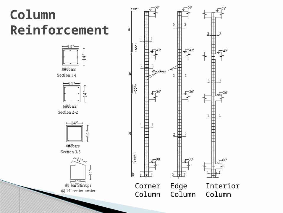
Column Reinforcement
Corner Column
InteriorColumn
Edge Column

Loading
Loading from Column
Surcharge loadFloor loading
Soil load resting on the footing
Footing Loading &Design
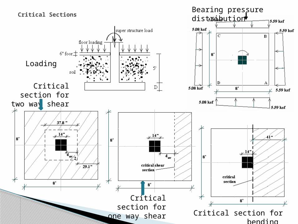
Critical Sections Bearing pressure distribution
Loading
Critical section for two way shear
Critical section for one way shear
Critical section for bending

FootingReinforcement

Retaining wall• Purpose• Behavior of wall Components• Design Sequence• Drainage System• Reinforcement Detailing
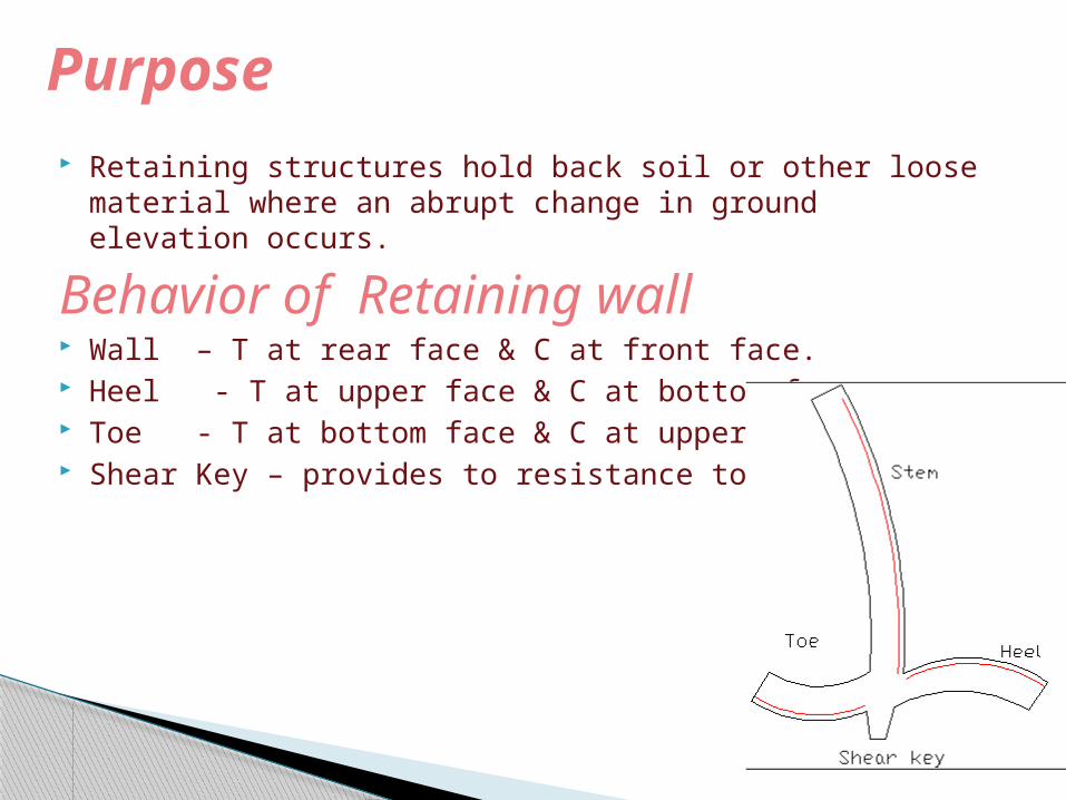
Retaining structures hold back soil or other loose material where an abrupt change in ground elevation occurs.
Behavior of Retaining wall Wall – T at rear face & C at front face. Heel - T at upper face & C at bottom face. Toe - T at bottom face & C at upper face. Shear Key – provides to resistance to sliding.
Purpose

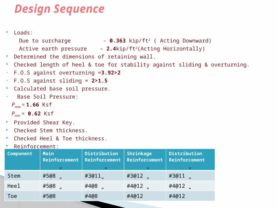
Loads: Due to surcharge - 0.363 kip/ft2 ( Acting Downward) Active earth pressure – 2.4kip/ft2(Acting Horizontally) Determined the dimensions of retaining wall. Checked length of heel & toe for stability against sliding & overturning.• F.O.S against overturning =3.92>2• F.O.S against sliding = 2>1.5 Calculated base soil pressure.• Base Soil Pressure: Pmax = 1.66 Ksf Pmin = 0.62 Ksf Provided Shear Key. Checked Stem thickness. Checked Heel & Toe thickness. Reinforcement:
Design Sequence
Component Main Reinforcement
Distribution Reinforcement
Shrinkage Reinforcement
Distribution Reinforcement
Stem #5@8” #3@11” #3@12” #3@11”Heel #5@8” #4@8” #4@12” #4@12”Toe #5@8” #4@8” #4@12” #4@12”
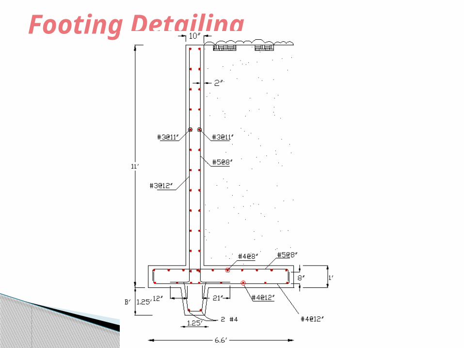
Footing Detailing
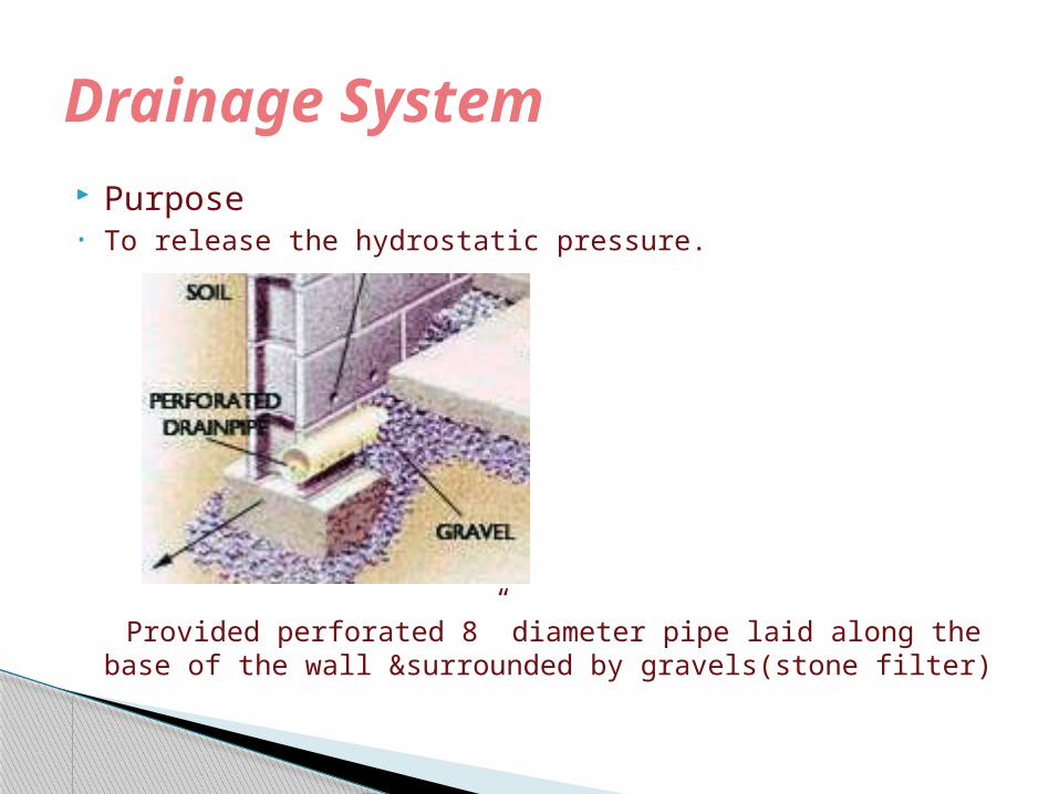
Purpose• To release the hydrostatic pressure.
Provided perforated 8” diameter pipe laid along the base of the wall &surrounded by gravels(stone filter)
Drainage System

Introduction Specification of Elevator Design Consideration Shear wall slab & footing Reinforcement detailing
Shear wall
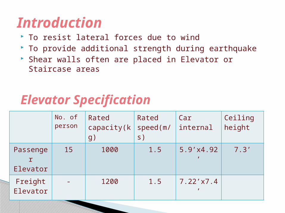
To resist lateral forces due to wind To provide additional strength during earthquake Shear walls often are placed in Elevator or Staircase areas
Elevator Specification
Introduction
No. of person
Rated capacity(kg)
Rated speed(m/s)
Car internal
Ceiling height
Passenger Elevator
15 1000 1.5 5.9’x4.92’ 7.3’
Freight Elevator
- 1200 1.5 7.22’x7.4’

Design Consideration Calculated wind load which is 26psf by using ACI code( Ps =λ I Ps30)
Vu< φVn
Calculated maximum shear strength permitted by φVn = φ 10 √fc hwd Calculated shear Strength provided by concrete is Vc = 3.3 √fc hwd + Nu d/4 lw
Vu<<φVc (No Shear reinforcement required) Calculating Area of steel which is governed by Minimum Reinforcement
in wall in our case Section has been checked by PCAcol. Provided Minimum wall Reinforcement governed by ACI.
• Vertical reinforcement Ast = 0.0012.b.dProvided #3@ 10
• Horizontal reinforcement Ast = 0.002.b.d Provided #3@ 6’
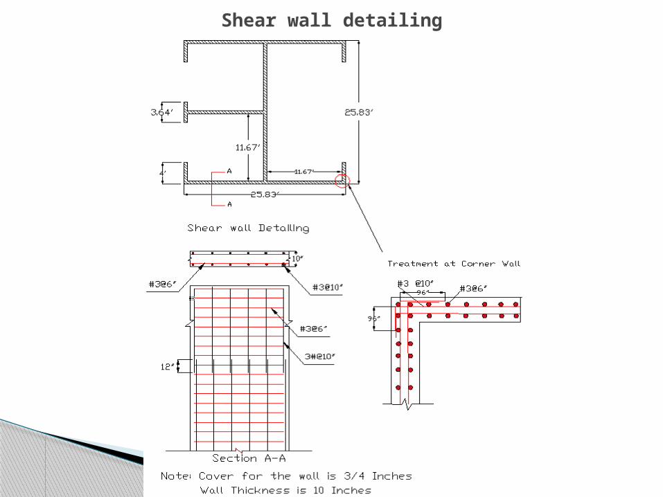
Shear wall detailing

Slab• Design Steps
◦ Load – 250k
◦ As =
◦ Reinforcement provided #5@ 6” (Both Direction) Footing• Design Steps
• Loads & moments calculated at the base of footing• Calculated factored Soil pressure = Factored load/Area• Desiged footing as a strip• Integrated 3 beams
Shear wall Slab & footing Design

Machine room Slab detailing

Shear wall Footing

Footing& Shear wall connection
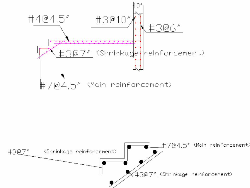
Staircase Shear Wall Footing for shear wall
Design

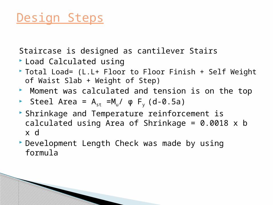
Staircase is designed as cantilever Stairs Load Calculated using Total Load= (L.L+ Floor to Floor Finish + Self
Weight of Waist Slab + Weight of Step) Moment was calculated and tension is on the top Steel Area = Ast =Mu/ φ Fy (d-0.5a) Shrinkage and Temperature reinforcement is calculated
using Area of Shrinkage = 0.0018 x b x d Development Length Check was made by using formula
Design Steps
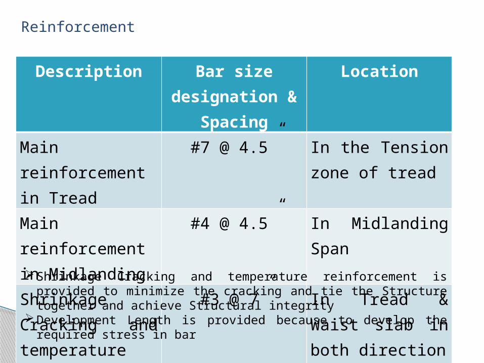
Description Bar size designation & Spacing
Location
Main reinforcement in Tread
#7 @ 4.5” In the Tension zone of tread
Main reinforcement in Midlanding
#4 @ 4.5” In Midlanding Span
Shrinkage Cracking and temperature reinforcement
#3 @ 7” In Tread & Waist slab in both direction
Reinforcement
Shrinkage Cracking and temperature reinforcement is provided to minimize the cracking and tie the Structure together and achieve Structural integrity
Development Length is provided because to develop the required stress in bar


Shear Wall
SHEAR WALL IS A STRUCTURAL ELEMENT USED TO RESIST LATERAL/HORIZONTAL/SHEAR FORCES PARALLEL TO THE PLANE OF THE WALL

Calculation of wind load which is 26psf by using ACI code Ps =λ I Ps30
Vu< φVn
Calculating maximum shear strength permitted by φVn = φ 10 √fc hwd Calculating shear Strength provided by Vc = 3.3 √fc hwd + Nu d/4 lw
Vu<<φVc (No Shear reinforcement required) Calculating Area of steel which is governed by Minimum Reinforcement in
wall in our case Minimum Reinforcement Wall Vertical Reinforcement Ast = 0.0012 x b x d Therefore providing # 3@ 7” Horizontal Reinforcement Ast =0.002 x b x d Therefore providing #3@ 10”
Design Steps
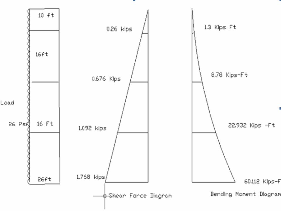


Loading◦Loading from Wall◦Surcharge load◦Soil load resting on the footing
Footing for Shear Wall
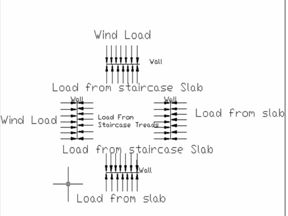

Loading at the Footing
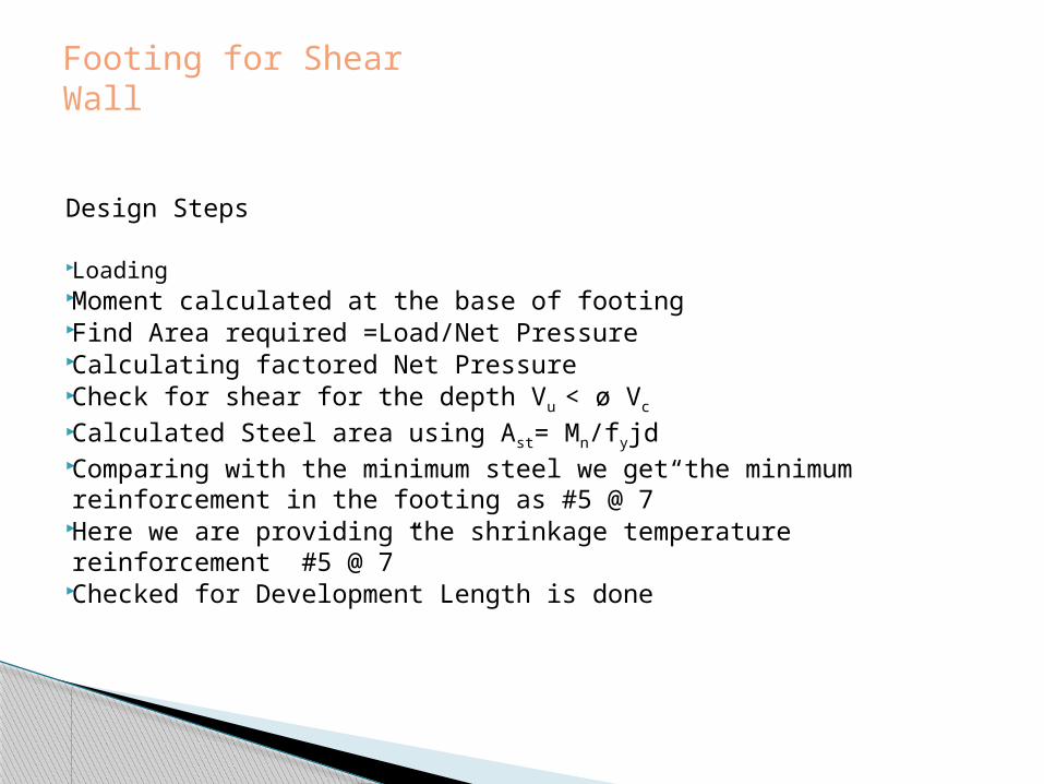
Design Steps
Loading Moment calculated at the base of footing Find Area required =Load/Net Pressure Calculating factored Net Pressure Check for shear for the depth Vu < ø Vc
Calculated Steel area using Ast= Mn/fyjd Comparing with the minimum steel we get the minimum reinforcement in
the footing as #5 @ 7” Here we are providing the shrinkage temperature reinforcement #5 @ 7” Checked for Development Length is done
Footing for Shear Wall


Green building is the practice of increasing the efficiency with which buildings use resources energy, water and materials
Helps in Minimizing Environment aspect like generation of pollution at the source risk to
human health and the environment
What is Green engineering?
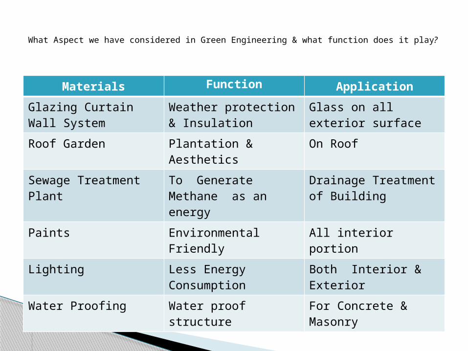
Materials Function ApplicationGlazing Curtain Wall System
Weather protection & Insulation
Glass on all exterior surface
Roof Garden Plantation & Aesthetics
On Roof
Sewage Treatment Plant
To Generate Methane as an energy
Drainage Treatment of Building
Paints Environmental Friendly
All interior portion
Lighting Less Energy Consumption
Both Interior & Exterior
Water Proofing Water proof structure For Concrete & Masonry
What Aspect we have considered in Green Engineering & what function does it play?

Function & Control
Airtight and weather resistant Air leakage control Rain Penetration Control by Pressure plate
Heat Loss by Cap connection Condensation Control Fire Safety
Glazing Curtain wall system
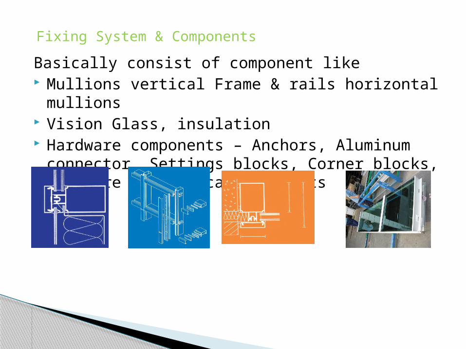
Basically consist of component like Mullions vertical Frame & rails horizontal mullions Vision Glass, insulation Hardware components – Anchors, Aluminum connector,
Settings blocks, Corner blocks, Pressure plates, caps, gaskets
Fixing System & Components
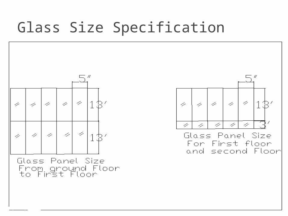
Glass Size Specification
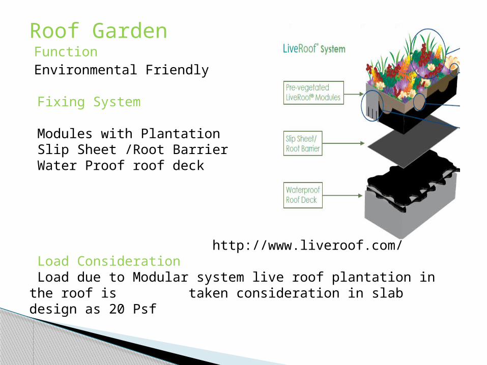
Function Environmental Friendly
Fixing System
Modules with Plantation Slip Sheet /Root Barrier Water Proof roof deck
http://www.liveroof.com/ Load Consideration Load due to Modular system live roof plantation in the roof is taken consideration in slab design as 20 Psf
Roof Garden

Advantage It generates Methane which can be used as a Source of
Energy. We can use the piping to send to appropriate location It is an Custom make and modular in size Maintenance and Operation cost is economical It maintains the BOD & COD level of Water is obtained
Sewage Treatment Plant

Schematic Representation of STP

Paint Using low voltaic organic components paint is beneficial.Lighting Using T5 Lamps, low mercury lamps helps in reduction in
energy consumptionWaterproofing Aquafin-IC is used a penetrating, inorganic, cementitious
material used to permanently waterproof
Other Green Engineering Component
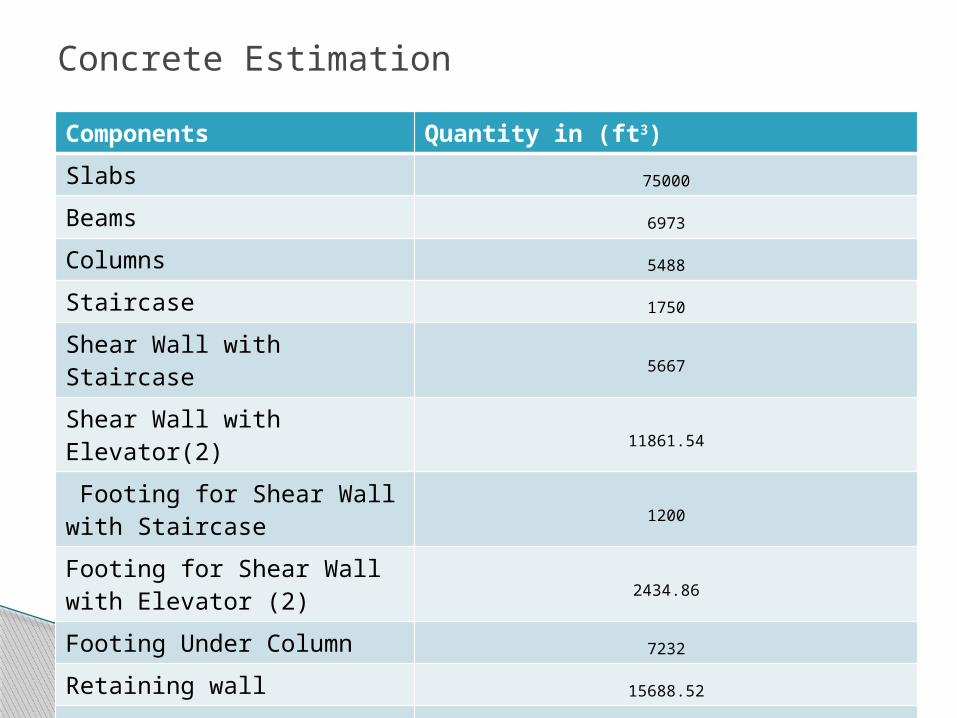
Components Quantity in (ft3)Slabs 75000
Beams 6973
Columns 5488
Staircase 1750
Shear Wall with Staircase 5667
Shear Wall with Elevator(2) 11861.54
Footing for Shear Wall with Staircase 1200
Footing for Shear Wall with Elevator (2) 2434.86
Footing Under Column 7232
Retaining wall 15688.52
Total 133294.9 cft
Concrete Estimation

Thank You