Embed Size (px)
Citation preview

MultiCraft International Journal of Engineering, Science and TechnologyVol. 10, No. 1, 2018, pp. 1-12
INTERNATIONALJOURNAL OF
ENGINEERING,SCIENCE ANDTECHNOLOGYwww.ijest-ng.com
www.ajol.info/index.php/ijest 2018 MultiCraft Limited. All rights reserved
Design of an adaptive overcurrent protection scheme for microgrids
Mohamed Awaad1, S. F. Mekhamer2, Almoataz Y. Abdelaziz2*
1 Electrical Power Control and Protection Sector, Petroleum Pipelines Company, Cairo, EGYPT2 Department of Electrical Power and Machines, Faculty of engineering, Ain shams University, Cairo, EGYPT
*Corresponding Author: e-mail: [email protected]
Abstract
Microgrid is a new phenomenon regarded to Distributed Generation (DG) penetration in the existing distribution systems. Inthis paper adaptive over current (OC) protection technique for a distribution system with DG penetration is proposed. Thisscheme takes into account general protection requirements, impacts of DG on protection system and protection coordination. Apart of IEEE 13 nodes radial distribution test feeder is taken as a study case to test the effectiveness of the proposed schemeusing ETAP software.
Keywords: Distributed Generator, Microgrids, Adaptive overcurrent protection, Protection Coordination.
DOI: http://dx.doi.org/10.4314/ijest.v10i1.1
1. Introduction
Based on environmental concerns related to emitted gases from conventional generation and the world trend to green energygeneration, DG technology has been developed. DG wide spread in distribution systems leads to an appeared phenomenon inpower system called Microgrids (MG). As a matter of fact MG can be seen as a group of DG units that can be operated either grid-connected to limit transmission losses and for peak shaving or islanded to avoid total outage when main utility get interrupted andhence increasing system reliability (Waleed et al., 2013). On the other hand, MG is considered as a collection of loads andgenerators with some local storage, which may appear as a net load or a net generator to the broader or host grid (Taha et al.,2012).
Even though DG connection to distribution system brings numerous benefits for MG, it poses significant challenges due tounforeseen short circuit (SC) increase in radial distribution system (Stefania, 2009), different fault levels during differenttopologies due to source change (Pukar et al., 2011; Andrés et al., 2012), bidirectional Power flow (Sachit et al., 2014), lack or insome cases completely loss of coordination in the existed protection scheme leads to undesired islanding and untimely tripping ofDGs protection relays (Stefania, 2009; Sachit et al., 2014), and a high DG penetration has resulted in the possibility of operatingdistribution system in islanded mode which has an issue in conventional OC protection system and needs a new requirement inprotection scheme (Pukar et al., 2011).
From the above mentioned challenges , it is clear that SC level is affected due to DGs insertion in distribution system that'sbecause fault current depends on source MVAs.c., and as MVAs.c. of main utility is higher than MVAs.c. of DG, so fault currentin grid connected will be higher than fault current in islanded mode of operation (Pukar et al,2011). This fault level variationimpacts on protection system as following (Pukar et al, 2011):1- If protective devices are adjusted to high fault values (as in conventional system), they will take longer time to trip or may not
trip at all when distributed system is converted to islanded mode.2- If distributed system now is transferred to islanded mode but protective devices are still adjusted to grid connected values (i.e.
higher fault levels). In this case if a fault is happened inside island itself and as any fault is followed by voltage drop, so bynot clearing the fault quickly not only loads but also some DGs will forced to be switched off. For example equipment likeM.V motors have a voltage variation limit to operate (+/- 10% of rated voltage) and also DGs.
Awaad et al./ International Journal of Engineering, Science and Technology, Vol. 10, No. 1, 2018, pp. 1-122
3- If protective devices are adjusted to islanded mode faults (i.e. low fault levels), they will make a false tripping when systemreconnected to the main utility.
Another important issue relate to DG penetration in distribution system is that DG changes the original (S.C and steady state)current values and directions on which relay settings in original radial system were calculated. Therefore IEEE std 1547 suggeststhat to maintain relays coordination due to high penetration of DGs, all DGs should be disconnected simultaneously after faulthappen (IEEE Std 1547, 2003), this would regain the system to its radial nature and hence maintain original relay coordination.However this solution isn't practical as DG becomes popular because it can feed loads without adding to T&D burden, so throwingoff all DGs every time a temporary fault happens would make the system unreliable, leads to sever stability problems and DGsynchronization problem during reconnecting again to distribution system after fault clearing (N. Schaefer et al, 2010; Sukumar etal, 2004; W. El-khattam et al, 2009; Ehsan et al, 2010). So it's expected in near future that DG will remain connected during gridfaults for feeding MG (N. Schaefer et al, 2010).
An attempt to solve different S.C. levels between grid-connected and islanded modes of operation is to insert a storage unit withMG for upgrading its S.C. level to values near the fault contributed by main grid to make MG fault possible to be detected bytraditional relays. However storage units require large investment and don't guarantee fault clearing on time unless they matchmain grid S.C. power (Pukar et al., 2011).
Based on the above mentioned DG impact on protection system, it's clear that conventional protection system will show a badresponse to MG protection, as MG has an operating philosophy which is under normal condition MG should operate in Grid-connected mode and in case of disturbance in main grid MG should continue to work in islanded mode. Therefore a new protectiontechnique that able to respond to both modes of operations is required (Sachit et al., 2014; Sohrab et al, 2014; Sohrab, Dalila et al.,2014).
As a result of that, various schemes for MG protection have been proposed which are adaptive protection, differential protection,OC and symmetrical components, distance protection, voltage based protection and deployment of external devices (Sachit et al,2014; Sohrab et al., 2014; Sohrab, Dalila et al., 2014). Based on the comparison among these various protection schemes, asproposed in (Sachit et al, 2014), it is clear that adaptive technique is cost reasonable and can be achieved with or withoutcommunication links, therefore in this research point we will deal with adaptive OC as a protection technique for MG, which canbe defined as " An online activity which is automatically able to change protection system parameters – either by externallygenerated signals or control action- to adapt them with new system configurations maintaining the basic criteria of sensitivity,selectivity, speed and reliability which guarantee a coordinated protection system " (Pukar et al, 2011; Andrés et al., 2012; A.Y.Abdelaziz et al., 2002).
Basically different adaptive techniques are existed and some of them are mentioned here. An adaptive protection scheme isproposed in (Alexandre et al., 2010) where a communication system connects MGCC to each directional OC relay. Off-lineanalysis is performed by constructing an event table for C.B statuses and an action table for relay settings in all MGconfigurations. During online operation, the MGCC is monitoring MG operating state and using the event and action tables toselect relays settings according to the current configuration. During real-time operation, the measured current values are comparedwith the relay settings to detect a fault if it is occurred. Fault current direction is also checked against an interlock direction. Thisscheme has the advantages of adapting to several MG configurations and Providing Protection for all fault types, but this scheme isnot efficient for larger MG configurations due to excessive memory used to store large amounts of off-line analysis data. Authorsin (Pukar et al., 2011) propose adaptive protection using local information only, to overcome the challenges of the OC protectionin distribution systems with DG. Relays trip characteristics are updated by detecting MG operating states (grid connected or islandor lose of some generators) and the faulted section. The faulted section is detected using time OC characteristics of directional OCrelays. This adaptive technique uses the state detection algorithms to know the network current condition and use also detection ofthe faulted section algorithm to update the relays trip characteristics to clear the fault as soon as possible. Here adaptive protectionis realized with the use of microprocessor-based DOCR and local information only which has the advantage that any problem witha relay will be confined in the relay itself. Authors don't uses communication system to update relay settings as they seecommunication system is complex and require high cost and isn't economical for small distribution systems. In (Hannu et al.,2010), an adaptive protection scheme for a LVMG using communication network between MG Management System (MGMS) andMG components (DGs, Relays, ..) is proposed. MGMS detects MG configuration change and sends the appropriate settings andpick-up limits to relays. This scheme protects against double phase faults. High speed communication links provide fast, selective,and reliable protection. However, it doesn't take into consideration the possibility of communication network failure and it alsodoesn't support plug-and-play DGs.
In the light of the above mentioned techniques, authors in (W. El-khattam et al., 2009) had summed up MG protection techniquesto two approaches to solve DOCR coordination problem as shown in Table 1.

Awaad et al./ International Journal of Engineering, Science and Technology, Vol. 10, No. 1, 2018, pp. 1-123
Table 1. Two approaches to solve the directional OC relay coordination problem associated with DG installationAdaptive Non-Adaptive
- Adaptive approach depends on changing or adapting relay setting based onsystem different topologies between (PG only or PG +All DGs or islandedor islanded+ (n-1) DGs).-It requires that relays must have multi SGF (switch group factor).-Relays settings can be changed by either Communication orCommunicationless.
Communication Communicationless- A communication network isconnected between the MGCPUand the different MG component.- MGCPU detecting the changein MG configuration and sendsthe appropriate settings and pick-up limits to the protective devicesfor each component (Hannu et al,2010).
The idea here is depending onprogramming each relay independentlyfor all possible configurations based onsystem configurations variation, usinglocal information only. Regarding localinformation only has an advantagewhich is any problem with a relay willbe related to relay itself (Pukar et al,2011).
-Non-adaptive approach depends oninserting an external device like FCL witheither main utility (to limit utilitycontribution to fault –when it is connected-and hence adjust relay setting for faultvalues of islanded mode) (Waleed et al,2013) or with DG(to limit DG contributionto fault to keep relay setting withoutchanges as traditional system withoutDGs).FCL isn't inserted with all DGs insystem, but optimal placement is made toselect the best DG to insert FCL (W. El-khattam et al, 2009).- Finally, FCL insertion aims to notchanging relay setting with differentconfigurations (i.e. use one setting group)
An integration of the proposed two approaches (Adaptive & Non-adaptive) is evolved in (W. El-khattam et al., 2009) trying toovercome problems that might appear due to the limitation of the above mentioned two approaches.
This work has a purpose to identify the impact of DG insertion on protection system of distribution grids, and hence theprotection requirements in the technique used to deal with these issues. Based on these requirements and different protectionschemes for MG, this work pretends to propose an adaptive OC protection technique for MG which responds, with allrequirements that maintain protection coordination, to a time-variable system like distribution system with DGs.
This paper is organized as follows: section 2 presents system case study and selection of system parameters and sources. Section3 presents protection impacts and requirements in system with DGs. Section 4 shows adaptive OC protection for distributionsystem with DG. Section 5 shows adaptive protection scheme results. In section 6 conclusion is presented. Finally references arelisted.
2. System case study
System case study is a part of IEEE 13 Bus test feeder and the One Line Diagram (OLD) is shown in Figure 1. System cable andT.Ls data are existed in (W.H. Kersting, 2001).
2.1 System Sources: Main utility ratings are 115 kV, 3984 MVAs.c. Also there are 3 DGs which are (Synchronous Generator (SynG1) at node 611: 1000 kW, 4.16 kV), (Synchronous Generator (Syn G2) at node 692: 1200 kW, 4.16 kV) and (two Wind TurbineGenerator (WTG) at WTG bus each one is 300 kW, 0.69kV).
With DG insertion in the system, multi configurations are evolved. In this work only 6 configurations are presented:Configuration1: Power Grid (PG) only. Configuration2: PG +All DGs.Configuration3: Islanded (IS) + All DG's. Configuration4: Is+ (All DG's - no WTG).Configuration5: Is+ (All DG's – no DG1). Configuration6: IS+ (All DG's - no DG2).
2.2 System Parameters Selection: All system Parameters (C.Bs, CTs, Switches, Buses, T.Ls and cables) are designed towithstand continuously and without damage maximum (faults and normal currents) that they may carry in different topologies. Asmotioned in the introduction S.C. level is depends on MVAs.c of source, so system parameters are designed based on Config. 2(PG+All DGs) as it contains all sources in service so it has maximum current and fault values as shown in Figure 2.

Awaad et al./ International Journal of Engineering, Science and Technology, Vol. 10, No. 1, 2018, pp. 1-124
Figure 1. System case study OLD including DGs.
Table 2 (a&b) shows maximum fault and maximum current that can be seen by different system parameters.Table 2
(a) Relays, CTS and CBs max FLA and S.C. (b) Buses and switches max FLA and S.C.
BUSMax. fault pass
in bus (kA)Max. FLA pass
in bus611 4.73 176.3684 5.82 150.2
VirtualBus1
7.89 19
VirtualBus2
7.89 32
WTG Bus 30.33 571.6675 7.13 126692 7.89 185671 7.89 202.3632 8.85 202.3
Bus 5 11.53 202.3Bus 1 20.89 7.3
SwitchesMax. fault passin switch (kA)
Max. FLA passin bus
S1 3.19 171.3S2 3.5 174.6S3 5.33 157.5S4 27.92 571.6S5 4.18 693.9
Relay C.T C.BMax.
fault seen byC.B (kA)
Max. FLAseen by C.B
R G1 CT g1 C.B g1 3.19 171.3R1 CT1 C.B1 3.57 150.2R2 CT2 C.B2 3.57 150.2R3 CT3 C.B3 4.17 150.2R4 CT4 C.B4 4.17 150.2R5 CT5 C.B5 7.8 19R
WTGCTwtg
C.Bwtg
4.43 94.808
R6 CT6 C.B6 5.85 125.6R7 CT7 C.B7 5.85 125.6R8 CT8 C.B8 7.73 32
R G2 CT g2 C.B g2 3.5 174.6R9 CT9 C.B9 5.33 157.5
R10 CT10 C.B10 4.18 693.9R11 CT11 C.B11 4.18 693.9R12 CT12 C.B12 5.78 693.9R13 CT13 C.B13 5.78 693.9R14 CT14 C.B14 20.87 7.3
LV C.B wtg1,2 1.84 285.4
Awaad et al./ International Journal of Engineering, Science and Technology, Vol. 10, No. 1, 2018, pp. 1-125
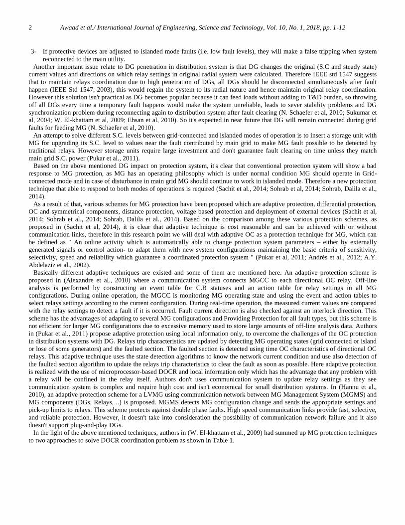
2.2.1 Switches selection: The switch FLA rating is designed such that the first available standard rate higher than 125% of maxFLA seen by switch is selected, and the momentary capacity is selected to be the first available standard rate higher than maximumfault seen by switch as clarified in Table 3 which shows maximum (FLA and faults) seen by each switch. These values areconsidered during selecting switches ratings.
Table 3. Switch Selection TableSwitch Max (A)
seen Switch Rating
(A)Max (kA)
seenSwitch
momentary (kA)Rated(kV)
BIL(kV)
SW1 171.3 300 3.19 6 4.8 24SW2 174.6 300 3.5 6 4.8 24SW3 157.5 200 5.33 6 4.8 30SW4 571.6 800 27.92 30 1 10SW5 693.9 800 4.18 6 4.8 24
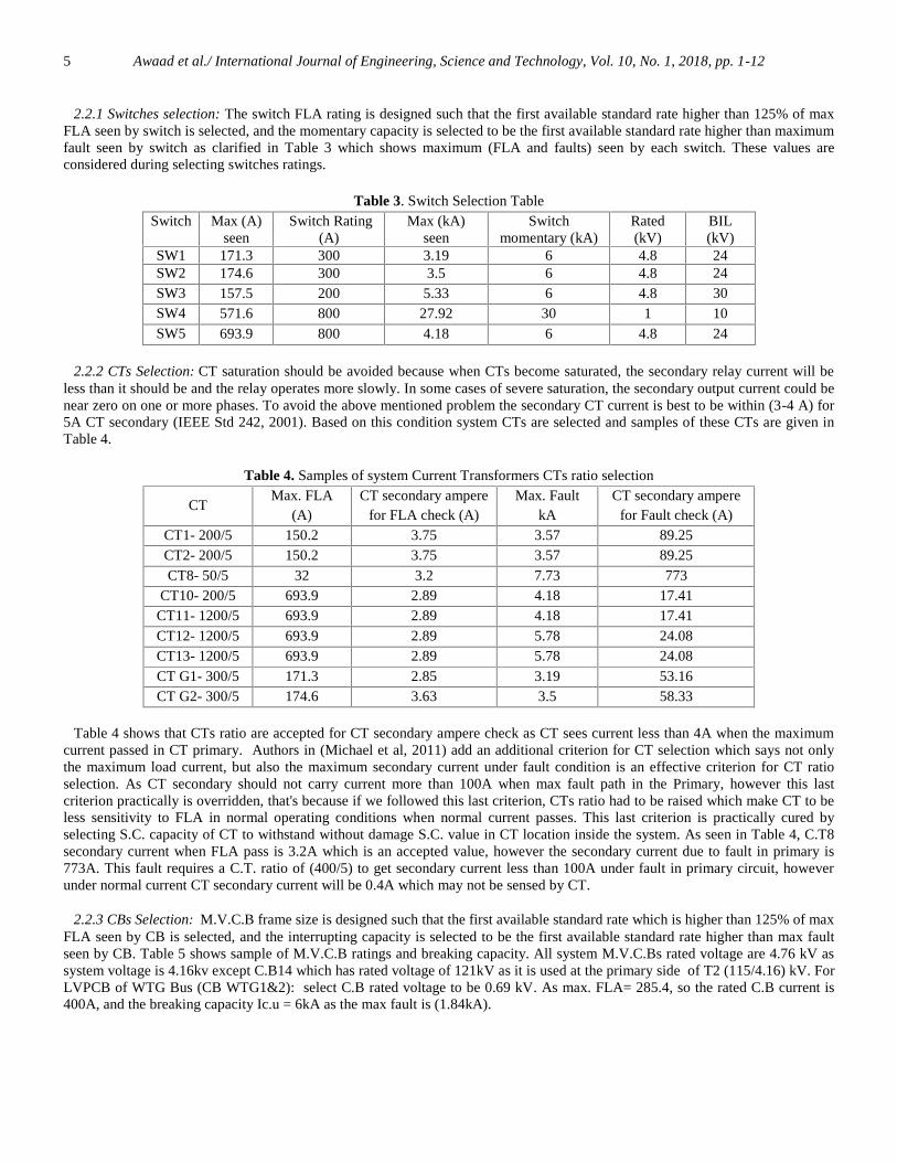
2.2.2 CTs Selection: CT saturation should be avoided because when CTs become saturated, the secondary relay current will beless than it should be and the relay operates more slowly. In some cases of severe saturation, the secondary output current could benear zero on one or more phases. To avoid the above mentioned problem the secondary CT current is best to be within (3-4 A) for5A CT secondary (IEEE Std 242, 2001). Based on this condition system CTs are selected and samples of these CTs are given inTable 4.
Table 4. Samples of system Current Transformers CTs ratio selection
CTMax. FLA
(A)CT secondary ampere
for FLA check (A)Max. Fault
kACT secondary ampere
for Fault check (A)CT1- 200/5 150.2 3.75 3.57 89.25CT2- 200/5 150.2 3.75 3.57 89.25CT8- 50/5 32 3.2 7.73 773
CT10- 200/5 693.9 2.89 4.18 17.41CT11- 1200/5 693.9 2.89 4.18 17.41CT12- 1200/5 693.9 2.89 5.78 24.08CT13- 1200/5 693.9 2.89 5.78 24.08CT G1- 300/5 171.3 2.85 3.19 53.16CT G2- 300/5 174.6 3.63 3.5 58.33
Table 4 shows that CTs ratio are accepted for CT secondary ampere check as CT sees current less than 4A when the maximumcurrent passed in CT primary. Authors in (Michael et al, 2011) add an additional criterion for CT selection which says not onlythe maximum load current, but also the maximum secondary current under fault condition is an effective criterion for CT ratioselection. As CT secondary should not carry current more than 100A when max fault path in the Primary, however this lastcriterion practically is overridden, that's because if we followed this last criterion, CTs ratio had to be raised which make CT to beless sensitivity to FLA in normal operating conditions when normal current passes. This last criterion is practically cured byselecting S.C. capacity of CT to withstand without damage S.C. value in CT location inside the system. As seen in Table 4, C.T8secondary current when FLA pass is 3.2A which is an accepted value, however the secondary current due to fault in primary is773A. This fault requires a C.T. ratio of (400/5) to get secondary current less than 100A under fault in primary circuit, howeverunder normal current CT secondary current will be 0.4A which may not be sensed by CT.
2.2.3 CBs Selection: M.V.C.B frame size is designed such that the first available standard rate which is higher than 125% of maxFLA seen by CB is selected, and the interrupting capacity is selected to be the first available standard rate higher than max faultseen by CB. Table 5 shows sample of M.V.C.B ratings and breaking capacity. All system M.V.C.Bs rated voltage are 4.76 kV assystem voltage is 4.16kv except C.B14 which has rated voltage of 121kV as it is used at the primary side of T2 (115/4.16) kV. ForLVPCB of WTG Bus (CB WTG1&2): select C.B rated voltage to be 0.69 kV. As max. FLA= 285.4, so the rated C.B current is400A, and the breaking capacity Ic.u = 6kA as the max fault is (1.84kA).

Awaad et al./ International Journal of Engineering, Science and Technology, Vol. 10, No. 1, 2018, pp. 1-126
Table 5. Samples of system M.V. C.Bs SelectionC.B Max. FLA (A) C.B rating (A) Max. Fault (kA) Rated Interruption Capacity (kA)CB1 150.2 225 3.57 8.8CB5 19 30 7.8 8.8CB6 125.6 200 5.85 8.8CB8 32 40 7.73 8.8CB9 157.5 200 5.33 8.8
CB13 693.9 1200 5.78 8.8CB14-121kV 7.3 20 20.87 31.5
CB G1 171.3 225 3.19 8.8CB G2 174.6 225 3.5 8.8
CB WTG 94.8 200 4.43 8.8
3. Protection impacts and requirements in system with DGs
3.1 DG Impact on Fault Current Level: It was outlined that DG has great impacts to S.C levels and reasons for this difference infault level between different topologies were mentioned in the introduction. To show clearly the impact of DG to fault levels it ishelpful to compare fault current level in different configurations with respect to (w.r.t) the fault levels for the system without DGsas shown in Figure 2.
(a) (b)Figure 2. % of fault magnitude (3ph, 1ph) for all nodes respects to fault currents of system without DGs:
(a) config. 2 (PG+ All DGs), (b) Config. 5 (IS+ All DGs-DG1)
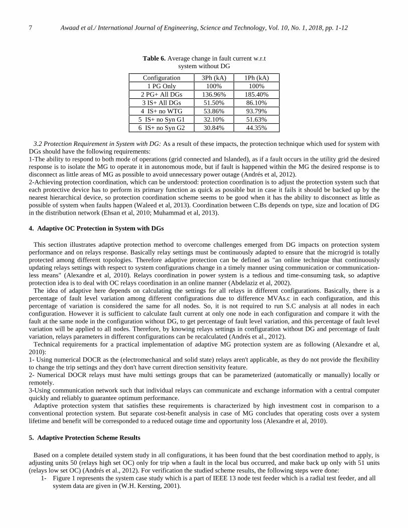
The following important notes are provided from Table 6 and Figure 2: 1-It is clear that topology 2 (PG+All DGs) has the greatest fault percentage among all topologies, that's due to the fault level isdependent on the MVAs.c of the source, and as this topology contains main power grid and all DGs so it has the largest MVAs.cand hence largest fault level. As a result of that we should design different system component (cable, C.B, Buses CT, …) capacityrating to withstand ,with a safe margin, this highest fault current as presented in section 2.2.2-It is observed that 1-phase fault is greater than 3Phase fault in all configurations contain DG, that's because DG has a greater onephase fault current.
Table 6 and Figure 2 show only the impact of DGs of fault level, but DGs have other impacts on the protection system.Generally these impacts on protection system depend on DG penetration level, connection point to distribution networks and DGtype and can be summarized in the following points (Andrés et al, 2012):1- Difference in fault levels.2-Bidirectional power flow due to high penetration, leads to undesired performance of protective devices if conventionalprotection technique is still used (Andrés et al, 2012; N. Schaefer et al, 2010; Muhammad et al, 2013).3-Un detectable faults or false trip protective devices.4-Lose of coordination.5-Interruption devices damage may occur as a result of fault current increase to values greater than interruption capacity ofdevices-as devices were sized to system fault level without DG.6-single phase fault greater than three phase fault due to DG have greater one phase fault current (as shown in above results).
Awaad et al./ International Journal of Engineering, Science and Technology, Vol. 10, No. 1, 2018, pp. 1-127
3.2 Protection Requirement in System with DG: As a result of these impacts, the protection technique which used for system withDGs should have the following requirements:1-The ability to respond to both mode of operations (grid connected and Islanded), as if a fault occurs in the utility grid the desiredresponse is to isolate the MG to operate it in autonomous mode, but if fault is happened within the MG the desired response is todisconnect as little areas of MG as possible to avoid unnecessary power outage (Andrés et al, 2012).2-Achieving protection coordination, which can be understood: protection coordination is to adjust the protection system such thateach protective device has to perform its primary function as quick as possible but in case it fails it should be backed up by thenearest hierarchical device, so protection coordination scheme seems to be good when it has the ability to disconnect as little aspossible of system when faults happen (Waleed et al, 2013). Coordination between C.Bs depends on type, size and location of DGin the distribution network (Ehsan et al, 2010; Muhammad et al, 2013).
4. Adaptive OC Protection in System with DGs
This section illustrates adaptive protection method to overcome challenges emerged from DG impacts on protection systemperformance and on relays response. Basically relay settings must be continuously adapted to ensure that the microgrid is totallyprotected among different topologies. Therefore adaptive protection can be defined as "an online technique that continuouslyupdating relays settings with respect to system configurations change in a timely manner using communication or communication-less means" (Alexandre et al, 2010). Relays coordination in power system is a tedious and time-consuming task, so adaptiveprotection idea is to deal with OC relays coordination in an online manner (Abdelaziz et al, 2002).
The idea of adaptive here depends on calculating the settings for all relays in different configurations. Basically, there is apercentage of fault level variation among different configurations due to difference MVAs.c in each configuration, and thispercentage of variation is considered the same for all nodes. So, it is not required to run S.C analysis at all nodes in eachconfiguration. However it is sufficient to calculate fault current at only one node in each configuration and compare it with thefault at the same node in the configuration without DG, to get percentage of fault level variation, and this percentage of fault levelvariation will be applied to all nodes. Therefore, by knowing relays settings in configuration without DG and percentage of faultvariation, relays parameters in different configurations can be recalculated (Andrés et al., 2012).
Technical requirements for a practical implementation of adaptive MG protection system are as following (Alexandre et al,2010):1- Using numerical DOCR as the (electromechanical and solid state) relays aren't applicable, as they do not provide the flexibilityto change the trip settings and they don't have current direction sensitivity feature.2- Numerical DOCR relays must have multi settings groups that can be parameterized (automatically or manually) locally orremotely.3-Using communication network such that individual relays can communicate and exchange information with a central computerquickly and reliably to guarantee optimum performance.
Adaptive protection system that satisfies these requirements is characterized by high investment cost in comparison to aconventional protection system. But separate cost-benefit analysis in case of MG concludes that operating costs over a systemlifetime and benefit will be corresponded to a reduced outage time and opportunity loss (Alexandre et al, 2010).
5. Adaptive Protection Scheme Results
Based on a complete detailed system study in all configurations, it has been found that the best coordination method to apply, isadjusting units 50 (relays high set OC) only for trip when a fault in the local bus occurred, and make back up only with 51 units(relays low set OC) (Andrés et al., 2012). For verification the studied scheme results, the following steps were done:
1- Figure 1 represents the system case study which is a part of IEEE 13 node test feeder which is a radial test feeder, and allsystem data are given in (W.H. Kersting, 2001).
Table 6. Average change in fault current w.r.tsystem without DG
Configuration 3Ph (kA) 1Ph (kA)1 PG Only 100% 100%
2 PG+ All DGs 136.96% 185.40%3 IS+ All DGs 51.50% 86.10%4 IS+ no WTG 53.86% 93.79%
5 IS+ no Syn G1 32.10% 51.63%6 IS+ no Syn G2 30.84% 44.35%
Awaad et al./ International Journal of Engineering, Science and Technology, Vol. 10, No. 1, 2018, pp. 1-128
2- Building the case study model presented in (Andrés et al,2012) on ETAP but with some edits :2.1- uniform all T.Ls in our model to be as the T.L between nodes (632-671) which is (3-phase, 4wire, 2000ft, ACSR(Aluminum Conductor Steel Reinforced), 556.5AWG) (W.H. Kersting, 2001).2.2- Upgrading DG2 rating from 0.5MW to 1.2MW.
3- Using ETAP S.C. module to perform maximum S.C. analysis to design or select breaking or S.C. withstand capacities fordifferent system parameters (C.Bs, Cable, T.Ls, Buses, and Switches). Really we perform max. S.C. analysis only inconfiguration#2 (PG+ all DGs) as it contains all sources so the largest MVAs.c, so largest faults among all configurations,as shown in Figure 2 and Table 6. This design criterion ensures that all system components withstand without damage anyS.C. values in any topology. Samples of system parameters max. S.C. seen and rated capacity are shown in Table3 forswitches, Table 4 for CTs and Table 5 for C.Bs.
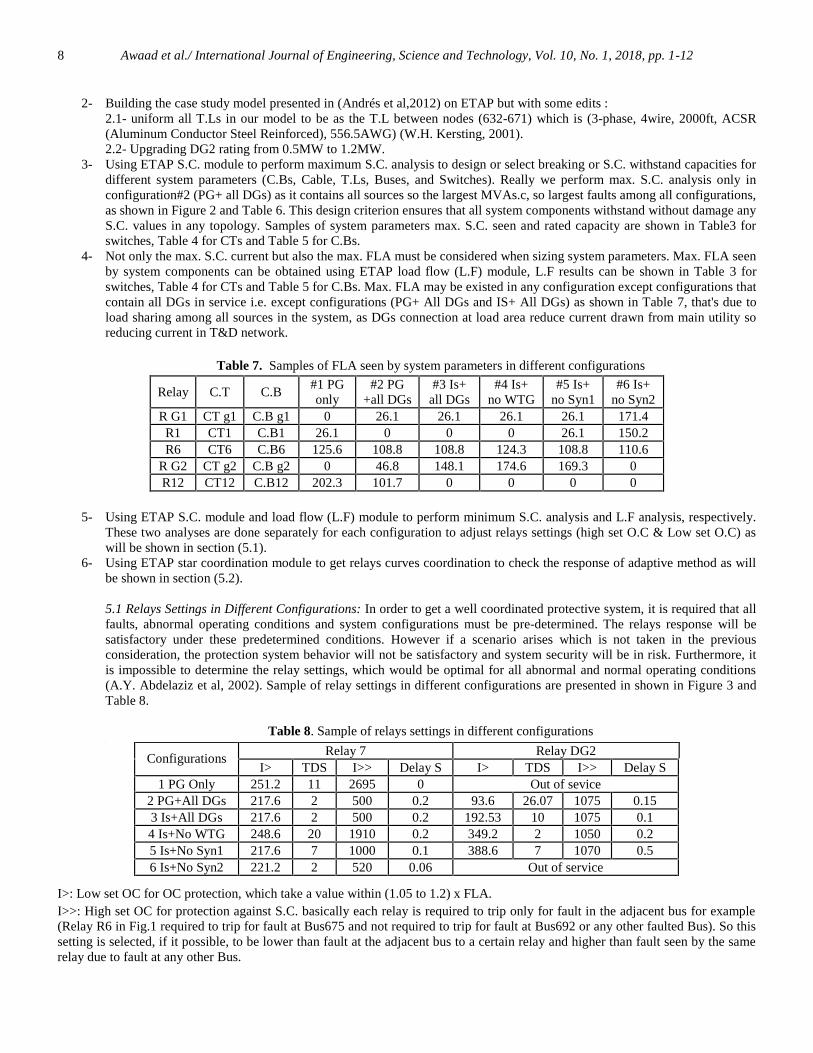
4- Not only the max. S.C. current but also the max. FLA must be considered when sizing system parameters. Max. FLA seenby system components can be obtained using ETAP load flow (L.F) module, L.F results can be shown in Table 3 forswitches, Table 4 for CTs and Table 5 for C.Bs. Max. FLA may be existed in any configuration except configurations thatcontain all DGs in service i.e. except configurations (PG+ All DGs and IS+ All DGs) as shown in Table 7, that's due toload sharing among all sources in the system, as DGs connection at load area reduce current drawn from main utility soreducing current in T&D network.
Table 7. Samples of FLA seen by system parameters in different configurations
Relay C.T C.B#1 PGonly
#2 PG+all DGs
#3 Is+all DGs
#4 Is+no WTG
#5 Is+no Syn1
#6 Is+no Syn2
R G1 CT g1 C.B g1 0 26.1 26.1 26.1 26.1 171.4R1 CT1 C.B1 26.1 0 0 0 26.1 150.2R6 CT6 C.B6 125.6 108.8 108.8 124.3 108.8 110.6
R G2 CT g2 C.B g2 0 46.8 148.1 174.6 169.3 0R12 CT12 C.B12 202.3 101.7 0 0 0 0
5- Using ETAP S.C. module and load flow (L.F) module to perform minimum S.C. analysis and L.F analysis, respectively.These two analyses are done separately for each configuration to adjust relays settings (high set O.C & Low set O.C) aswill be shown in section (5.1).
6- Using ETAP star coordination module to get relays curves coordination to check the response of adaptive method as willbe shown in section (5.2).
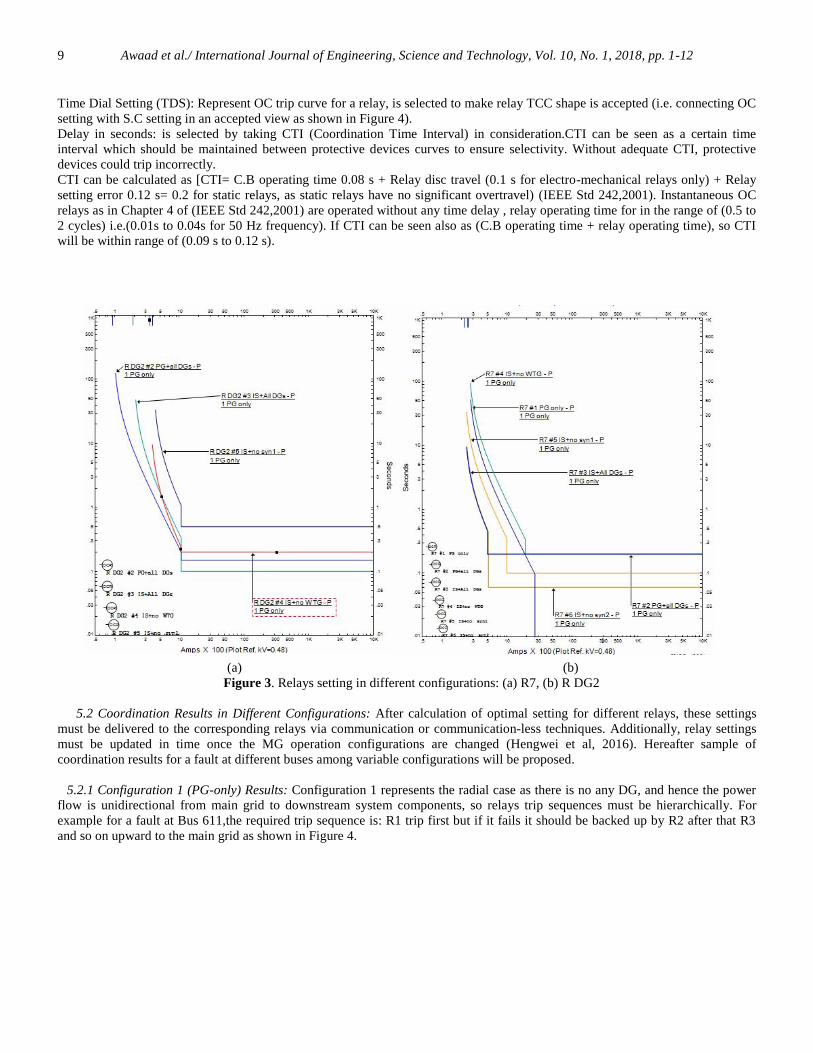
5.1 Relays Settings in Different Configurations: In order to get a well coordinated protective system, it is required that allfaults, abnormal operating conditions and system configurations must be pre-determined. The relays response will besatisfactory under these predetermined conditions. However if a scenario arises which is not taken in the previousconsideration, the protection system behavior will not be satisfactory and system security will be in risk. Furthermore, itis impossible to determine the relay settings, which would be optimal for all abnormal and normal operating conditions(A.Y. Abdelaziz et al, 2002). Sample of relay settings in different configurations are presented in shown in Figure 3 andTable 8.
Table 8. Sample of relays settings in different configurations.
.
.
I˃: Low set OC for OC protection, which take a value within (1.05 to 1.2) x FLA.I˃˃: High set OC for protection against S.C. basically each relay is required to trip only for fault in the adjacent bus for example(Relay R6 in Fig.1 required to trip for fault at Bus675 and not required to trip for fault at Bus692 or any other faulted Bus). So thissetting is selected, if it possible, to be lower than fault at the adjacent bus to a certain relay and higher than fault seen by the samerelay due to fault at any other Bus.
Relay 7 Relay DG2Configurations
I˃ TDS I˃˃ Delay S I˃ TDS I˃˃ Delay S1 PG Only 251.2 11 2695 0 Out of sevice
2 PG+All DGs 217.6 2 500 0.2 93.6 26.07 1075 0.153 Is+All DGs 217.6 2 500 0.2 192.53 10 1075 0.14 Is+No WTG 248.6 20 1910 0.2 349.2 2 1050 0.25 Is+No Syn1 217.6 7 1000 0.1 388.6 7 1070 0.56 Is+No Syn2 221.2 2 520 0.06 Out of service
Awaad et al./ International Journal of Engineering, Science and Technology, Vol. 10, No. 1, 2018, pp. 1-129
Time Dial Setting (TDS): Represent OC trip curve for a relay, is selected to make relay TCC shape is accepted (i.e. connecting OCsetting with S.C setting in an accepted view as shown in Figure 4).Delay in seconds: is selected by taking CTI (Coordination Time Interval) in consideration.CTI can be seen as a certain timeinterval which should be maintained between protective devices curves to ensure selectivity. Without adequate CTI, protectivedevices could trip incorrectly.CTI can be calculated as [CTI= C.B operating time 0.08 s + Relay disc travel (0.1 s for electro-mechanical relays only) + Relaysetting error 0.12 s= 0.2 for static relays, as static relays have no significant overtravel) (IEEE Std 242,2001). Instantaneous OCrelays as in Chapter 4 of (IEEE Std 242,2001) are operated without any time delay , relay operating time for in the range of (0.5 to2 cycles) i.e.(0.01s to 0.04s for 50 Hz frequency). If CTI can be seen also as (C.B operating time + relay operating time), so CTIwill be within range of (0.09 s to 0.12 s).
(a)
(b)(c)(d)(e)(f)(g)(h)(i)(j)(k)(l)(m)(n)(o)(p)
(a)
(b)(a) (b)
Figure 3. Relays setting in different configurations: (a) R7, (b) R DG2
5.2 Coordination Results in Different Configurations: After calculation of optimal setting for different relays, these settingsmust be delivered to the corresponding relays via communication or communication-less techniques. Additionally, relay settingsmust be updated in time once the MG operation configurations are changed (Hengwei et al, 2016). Hereafter sample ofcoordination results for a fault at different buses among variable configurations will be proposed.
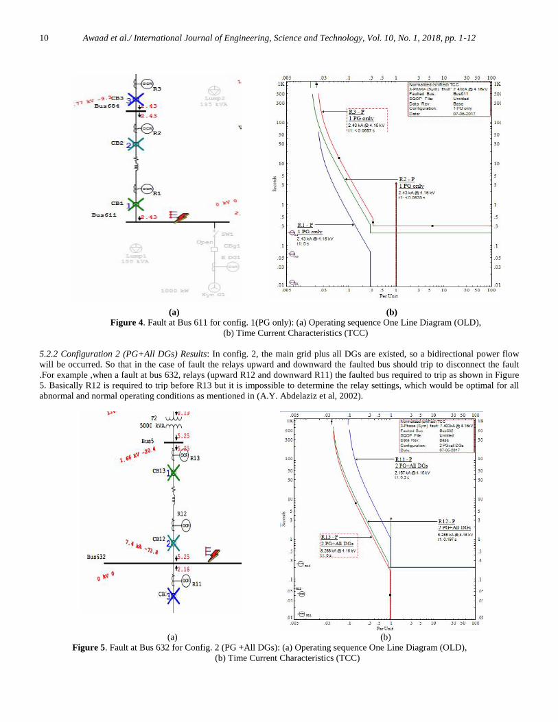
5.2.1 Configuration 1 (PG-only) Results: Configuration 1 represents the radial case as there is no any DG, and hence the powerflow is unidirectional from main grid to downstream system components, so relays trip sequences must be hierarchically. Forexample for a fault at Bus 611,the required trip sequence is: R1 trip first but if it fails it should be backed up by R2 after that R3and so on upward to the main grid as shown in Figure 4.
Awaad et al./ International Journal of Engineering, Science and Technology, Vol. 10, No. 1, 2018, pp. 1-1210
(a)
(a) (b)Figure 4. Fault at Bus 611 for config. 1(PG only): (a) Operating sequence One Line Diagram (OLD),
(b) Time Current Characteristics (TCC)
5.2.2 Configuration 2 (PG+All DGs) Results: In config. 2, the main grid plus all DGs are existed, so a bidirectional power flowwill be occurred. So that in the case of fault the relays upward and downward the faulted bus should trip to disconnect the fault.For example ,when a fault at bus 632, relays (upward R12 and downward R11) the faulted bus required to trip as shown in Figure5. Basically R12 is required to trip before R13 but it is impossible to determine the relay settings, which would be optimal for allabnormal and normal operating conditions as mentioned in (A.Y. Abdelaziz et al, 2002).
(a) (b)Figure 5. Fault at Bus 632 for Config. 2 (PG +All DGs): (a) Operating sequence One Line Diagram (OLD),
(b) Time Current Characteristics (TCC)

Awaad et al./ International Journal of Engineering, Science and Technology, Vol. 10, No. 1, 2018, pp. 1-1211
6. Conclusion
Adaptive OC protection technique based on system topological change for a distribution system with DG has been proposed.Results show that this protection scheme works well for MG and it is an effective tool to deal with protection issues related to DGpenetration, as it success to preserve protection coordination between relays among different system configurations. The abovework shows that the best coordination method is adjusting units 50 (relays high set O.C) to trip only when a fault in the local busoccurred, and make back up only with 51 units (relays low set O.C).For future work adaptive OC protection will be applied for thesame system case study, but after converting it from radial to ring and obtaining results simulated to that are presented in thispaper.
Nomenclature
DG Distributed Generator.MG Micro-Grids.MGCC MG Central Controller.DOCR Directional OC Relay.MGCPU MG Central Protection Unit.FCL Fault Current Limiter.BIL Basic Insulation Level.
References
Abdelaziz A.Y., Talaat H.E.A., Nosseir A.I., Hajjar A.A., 2002. An adaptive protection scheme for optimal coordination ofovercurrent relays. Electric Power Systems Research, Vol. 61, pp. 1–9.
Bamber M., Darby A., 2011. Network Protection & Automation Guide, Chapter 9.Brahma S.M., Girgis A.A., 2004. Development of adaptive protection scheme for distribution systems with high penetration of
distributed generation. IEEE Transaction on Power Delivery, Vol. 19, No. 1, pp. 56-63.Conti S., 2009. Analysis of distribution network protection issues in presence of dispersed generation. Electrical Power System
Research, Vol. 79, pp. 49–56.Contreras A.F., Ramos G.A., Ríos M.A., 2012. Methodology and design of an adaptive overcurrent protection for distribution
systems with DG. International Journal of Engineering & Technology, Vol. 12, No. 4, pp. 128- 136.El-khattam W., Sidhu T.S., 2009. Resolving the impact of distributed renewable generation on directional overcurrent relay
coordination: a case study. IET Renewable Power Generation, Vol. 3, No. 4, pp. 415-425.Farooqi M.R., 2013. Effect of distributed generation on protective device coordination in distribution system. ECE Department
University of Western Ontario, pp. 1-15.Gopalan S.A., Sreeram V., Iu H.C., 2014. A review of coordination strategies and protection schemes for microgrids. Renewable
and Sustainable Energy Reviews Vol. 32, pp. 222–228.IEEE Std 1547-2003, 2003. IEEE Standard for Interconnection Distributed Resources with Electric Power System.IEEE Std 242-2001, 2001. IEEE Recommended Practice for Protection and Coordination of Industrial and Commercial Power
Systems. Chapter4 & Chapter15.Kersting W.H., 2001. Radial Distribution Test Feeders. Distribution Systems Analysis Subcommittee Report, IEEE.Laaksonen H.J., 2010. Protection Principles for Future Microgrids. IEEE Transactions on Power Electronics, Vol. 25, No. 12, pp.
2910-2918.Lin H., Guerrero J.M., Jia C., Liu C., 2016. Adaptive overcurrent protection for microgrids in extensive distribution systems.
IECON 2016 - 42nd Annual Conference of the IEEE Industrial Electronics Society, pp. 4042 - 4047.Mahat P., Chen Z., Bak-Jensen B., Bak C.L., 2011. A simple adaptive overcurrent protection of distribution systems with
distributed generation. IEEE Transaction on Smart Grid, Vol. 2, No. 3, pp. 428-437.Mirsaeidi S., Said, D.M., Mustafa M.W., Habibuddin, M.H., Ghaffari K., 2014. An analytical literature review of the available
techniques for the protection of micro-grids. Electrical Power and Energy Systems Vol. 58, pp. 300–306.Mirsaeidi S., Said D.M., Mustafa M.W., Habibuddin M.H., Ghaffari K., 2014. Progress and problems in micro-grid protection
schemes. Renewable and Sustainable Energy Reviews Vol. 37, pp. 834–839.Oudalova A., Fidigatti A., 2010. Adaptive Network Protection in MicroGrids. ABB Switzerland Ltd, ABB SACE S.p.A, pp.1-24.Reihani E., Norouzizadeh R., Davodi M., Davodi M., 2010. Adaptive protection of distribution grids with distributed generation.
Power and Energy Engineering Conference (APPEEC), Asia-Pacific, pp. 1-4.Schaefer N., Degner T., Shustov A., Keil T., Jaeger J., 2010. Adaptive protection system for distribution networks with distributed
energy resources. Fraunhofer IWES (formerly ISET e.V.), Germany, Koenigstor Vol. 59, pp. 1-5.Ustun T.S., Ozansoy C., and Zayegh A., 2012. Fault current coefficient and time delay assignment for microgrid protection system
with central protection unit. IEEE Transactions on Power Systems, pp. 1-8.

Awaad et al./ International Journal of Engineering, Science and Technology, Vol. 10, No. 1, 2018, pp. 1-1212
Waleed K. A. Najy, H. H. Zeineldin, W. L. Woon, 2013. Process Optimal Protection Coordination for Microgrids with Grid-Connected and Islanded Capability. IEEE Transactions on Industrial Electronics ,Volume: 60, Issue: 4, pp. 1668 - 1677.
Biographical notes
Mohamed Awaad was born in Cairo, Egypt, on October 10, 1988. He received the B. Sc. degree in electrical engineering from The Higher Institute ofEngineering, El-Shrouq City, Egypt in 2011. He is now working for the M. Sc. degree in electrical engineering from Ain-Shams University, Cairo, Egypt.Currently, he is working at Electrical Power Control and Protection Sector, Petroleum Pipelines Company (PPC), Cairo. His research interests include adaptiveprotection of microgrids.
Said F. Mekhamer was born in Egypt in 1964. He received the B. Sc. and M.Sc. degrees in electrical engineering from Ain Shams University, Cairo, Egypt, andthe Ph.D. degree in electrical engineering from Ain Shams University with joint supervision from Dalhousie University, Halifax, NS, Canada, in 2002. He iscurrently an Associate Professor in the Department of Electric Power and Machines, Ain Shams University. His research interests include power system analysis,power system protection, and applications of AI in power systems.
Almoataz Y. Abdelaziz received the B.Sc. and M.Sc. degrees in electrical engineering from Ain Shams University, Egypt, in 1985 and 1990, respectively, and thePh.D. degree in electrical engineering according to the channel system between Ain Shams University, Egypt, and Brunel University, U.K., in 1996. He is currentlya Professor of electrical power engineering at Ain Shams University. Dr. Abdelaziz is the chair of IEEE Education Society chapter in Egypt, senior editor of AinShams Engineering Journal, editor of Electric Power Components & Systems Journal, editorial board member, associate editor and editorial advisory boardmember of several international journals and conferences. He is also a member in IET and the Egyptian Sub-Committees of IEC and CIGRE’. He has been awardedmany prizes for distinct researches and for international publishing from Ain Shams University, Egypt. He has authored or coauthored more than 300 refereedjournal and conference papers in his research areas which include the applications of artificial intelligence, evolutionary and heuristic optimization techniques topower system operation, planning, and control.
Received June 2017Accepted June 2017Final acceptance in revised form September 2017