Embed Size (px)
Citation preview

Design of Airframe-Integrated, Distortion-
Tolerant Propulsion Systems
Razvan V. Florea, Larry W. Hardin, Gregory Tillman, Aamir Shabbir, and
Om P. Sharma
United Technologies Research Center
David J. Arend
NASA Glenn Research Center
Presented by Razvan V. Florea
NASA 2011 Fundamental Aeronautics Meeting
Cleveland, Ohio
March 17, 2011

Acknowledgements
This presentation summarizes work performed by United Technologies Research
Center (UTRC) and Pratt & Whitney under NASA Contract NNC07CB59C,
Robust Design for Embedded Engine Systems (RDEES), Phase 2. Financial
support was provided by NASA under the Subsonic Fixed Wing Project. Parallel
project work conducted by Va Tech University is described in a separate
presentation.
The authors wish to acknowledge technical contributions and guidance provided
by Dr. Claude Matalanis and Mr. Mark Stucky of UTRC; Dr. Wesley Lord and
Mssrs. Karl Hasel and Tom Case of Pratt & Whitney; Mssrs. Ron Kawai and
Doug Friedman of the Boeing Company; Dr. Milt Davis of Arnold Engineering
Development Center; and Mr. Jeff Berton of NASA Glenn Research Center.

Update and quantify the expected 5 – 10% achievable BLI vehicle-level performance benefit
Leverage previous open-literature BLI system studies
Perform high-level, propulsion-system-focused, vehicle-level system study using UTRC’s Integrated Total Aircraft Power Systems (ITAPS) experience
Develop a distortion-tolerant fan stage design that simultaneously targets less than 2% reduced efficiency and less than 2% reduced stall margin relative to a clean-inflow baseline
Utilize full-wheel, unsteady 3-D CFD fan design capability
Ensure fan design consistent with achieving maximum BLI vehicle-level fuel burn benefits
N+2 Program Goals

Previous Studies on BLI Propulsion
Bangert, et al., NASA-CR-3743 (1983)
Daggett, et al., NASA-CR-2003-212670
Berrier, NASA-TP-2005-213766
Campbell, AIAA 2005-0459
Kawai, et al., NASA-CR-2006-214534
Carter, AIAA JOA 2006, Vol 43, No. 5
Plas, MIT PhD Thesis 2006
Plas, et al., AIAA 2007-450
Kawai, NASA-CR-2008-215141
Nikol, NASA-TM-2008-215112
Drela, AIAA 2009-3762
Nikol, McCuller, AIAA 2009-931
15%
10%
5%
Aircraft Fuel
Burn Reduction
Boeing
(Daggett, et al., 2003)
MIT
(Plas, et al., 2007)
NASA
(Nickol, et al., 2009)
Boeing
(Kawai, et al., 2006)

Limiting Theoretical Benefits
8
6
4
2
0
Pro
pu
lsiv
e E
ffic
ien
cy o
r T
SF
C B
en
efit (%
)
Max Benefit for 12.4% BLI (aircraft upper
center area, LE to TE)
(Smith1, 1993)
3-engine flush,
AR = 1
Propulsive Efficiency BLI Benefit for Advanced HWB Aircraft (Boeing N2A-EXTE)
Relative to Clean-Inflow, Advanced Technology Podded Baseline
3-engine,
AR = 3
3-engine,
AR = 7
Distributed Fan
Propulsion, AR = 7
5-engine,
AR = 4
R = 1
R = 0R = 1
R = 0
Max Benefit for 11% BLI (aircraft upper
surface to x/c = 0.8)
(Smith1, 1993)
5-engine,
AR = 2
1Smith, L. H., Wake Ingestion Propulsion Benefit. AIAA Journal of Propulsion and Power, Vol. 9, No. 1, Jan. – Feb., 19932Lord, W. K., Personal Communication. Pratt & Whitney, May 20103Tillman, T. G., Hardin, L. W., Moffitt, B. A., Sharma, O. P., Lord, W. K., Berton, J., and Arend, D., System-Level Benefits
of Boundary Layer Ingesting Propulsion. Invited presentation, AIAA 49th Aerospace Sciences Meeting, January 2011.
Max Benefit for 15% BLI (ideal propulsor,
aircraft upper center surface to x/c = 0.9)
(Lord2, 2010)
Propulsion / airframe integration configuration can determine ingested boundary layer
drag fraction & resulting maximum achievable upper benefit
Theory (Smith1) Cycle Analysis
(NPSS3)
AR = Inlet Aspect Ratio (Width / Height)
w
jj
VV
VVR w
0
1

System Study Approach
Parameter Units
Engine BLI benefit % TSFC
Nacelle drag reduction % Aircraft Drag
Nacelle weight reduction % TSFC
Inlet weight increase % TSFC
Inlet excess pressure loss % TSFC
Flow control bleed / hp
extractions
% TSFC
Fan efficiency reduction % TSFC
BLI Benefits
BLI Penalties
• High-level system study to define design directions &
enabling technology investments
• Advanced technology baseline propulsion system (BPR = 16,
FPR = 1.35 UHB propulsion system)
• Study based on engine sensitivities & aircraft trade factors for
a single, advanced UHB engine cycle
• Impact of propulsion / airframe integration and engine weight
not addressed (i.e., aircraft volume changes, external contour
modifications, inlet / airframe design, etc.)
• Engine sensitivities obtained using NPSS models; other
inputs from simple, low-order models
• Aircraft trade factors from ITAPS advanced commercial
transport aircraft (similar to Boeing BWB reference aircraft)
Engine Sensitivities Help Identify Technology Challenges:
High-performance,
distortion-tolerant fan
Low-loss, distortion-
optimized inlet
Flow control extraction penalties
challenging in light of limiting
theoretical benefits

System Study Results
• Boeing N2A-exte reference vehicle (using UTRC ITAPS large commercial transport blended
vehicle trade factors)
• Podded, aft, advanced technology UHB baseline propulsion system (BPR = 16, FPR = 1.35)
• 5-engine architecture relative to 5-engine podded baseline to highlight BLI benefit
• Study was carried out for a fixed engine cycle and did not incorporate engine weight or
propulsion / airframe integration effects on the aircraft
• Comparatively small ingested drag fraction for the study aircraft limits the maximum
achievable benefit (upper, center fuselage boundary layer yields D / T ~12-15%)
AR = Inlet Aspect Ratio (Width / Height)
Propulsion system architectures that provide system-
level benefits require low-loss, low-drag inlets
BLI benefit limited by viscous drag accessible
on N+2 vehicle upper surface (D / T = 12-15%)1
1Figure & CFD solution from the Boeing Company, Kawai, R. T., Friedman, D. L.,
and Serrano, L., Blended Wing Body (BWB) Boundary Layer Ingestion (BLI) Inlet
Configuration and System Studies, NASA CR-2006-213534, December 2006.

System Study Identifies Key BLI-Enabling Technologies
• Inlet flow control
• Laminar flow wings
High-performance, distortion-
tolerant turbomachinery
Compact, low-loss,
low-drag inlet

Optimization-based Parametric Inlet Design for Embedded Propulsion
25 global control points (blue) manipulate ~3000
detailed mesh control points (red)
• Automated optimization enables exploration of wide
regions of multi-parameter design space
• Toolset can analyze over 1000 cases in a week
• New grid morphing capability (SCULPTOR) key enabler
• Inlet aspect ratio
• Lip contour & thickness
• Duct offset & length
• Wall curvature & shape
• Upstream airframe contour
Minimize total pressure
loss & distortion

Distortion-Optimized Inlet Design Progression
NASA Inlet A: Baseline (AR = 1.9, L / D = 3, highly offset)
UTRC A: Shape-optimized Inlet A with flow control
UTRC PA: Improved UTRC A with use of high-fidelity, viscous CFD and automated optimization
UTRC P1: Point of departure for global optimization; reduced L / D from 1.5 to 0.8; implemented
reduced offset
UTRC P2: Local inlet wall shape optimization of P1
UTRC P3: Combined global / local shape optimization including inlet lip & U. S. airframe contour
UTRC P4: Final inlet design including optimization of inlet lip & U. S. airframe contour; L / D reduced
from 0.8 to 0.6
Inlet A UTRC A UTRC P1 UTRC P4
Baseline Geometry: CFD Results
Detailed flow field solution
Throat Section Mid-plane Section AIP Section
Figure 1. Total pressure field for the NASA “inlet A” at reference conditions at throat section, along the inlet’s
mid-plane, and AIP cross-section.
Point of departure for
UTRC P-series inlets
Aerodynamic Interface Plane (AIP) total pressure contours

NASA Inlet A
1
2
0.5
1
Inle
t e
xce
ss to
tal p
ressu
re loss (
ΔP
T/
PT
1),
%
Red
uctio
n o
f d
isto
rtio
n h
arm
on
ic
am
plit
ude (
no
rma
lize
d to
NA
SA
In
let A
)
UTRC A
UTRC
Parametric A
UTRC P1 UTRC P2
NASA A
UTRC A
UTRC PA
UTRC P1
UTRC P2
0 0
RDEES Phase 1
RDEES Phase 2
Optimization-based Parametric Inlet DesignDesign progression summary
• Inlet excess pressure loss reduced ~3x relative to Phase 1 optimized
inlet & ~4 – 5x relative to original Inlet A starting point
• Dominant distortion harmonic amplitudes reduced ~30 – 50% relative
to original Inlet A starting point
Largest reduction of the first
three harmonic amplitudes
P4
P4

Fan Response to Distortion-Optimized Inlet
Fan Efficiency Reduction (%)
Inlet enables fan to meet
performance target
Inlet A P3 Inlet
Δβ (deg.)
Excursions in Fan Blade L. E. Relative Incidence from Clean Inflow
Inlet significantly improves fan
interaction with incoming distortion
(Two U. S. BC’s)
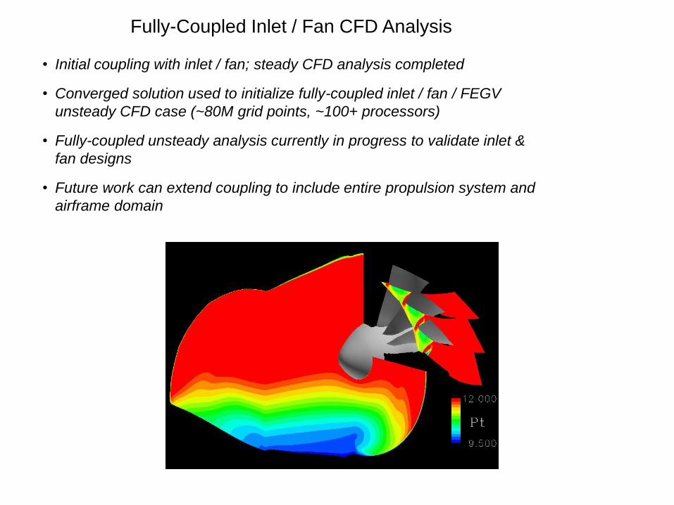
Fully-Coupled Inlet / Fan CFD Analysis
• Initial coupling with inlet / fan; steady CFD analysis completed
• Converged solution used to initialize fully-coupled inlet / fan / FEGV
unsteady CFD case (~80M grid points, ~100+ processors)
• Fully-coupled unsteady analysis currently in progress to validate inlet &
fan designs
• Future work can extend coupling to include entire propulsion system and
airframe domain

Conclusions
• A high-level, trade-factor-based system study has demonstrated that significant system-
level benefits can be achieved with BLI propulsion
• Study used a fixed, ultra high bypass ratio advanced engine cycle and Boeing N+2 BWB aircraft; engine weight &
propulsion / airframe integration effects were not considered
• ~3 – 5% fuel burn benefit identified for current N+2 study
• Significantly larger benefits (order ~10%) are possible for N+3 configurations where more airframe boundary layer
may be ingested into the engines
• The benefits of flow control were found to be largely offset by engine extraction penalties for N+2 airframe & limited
BLI available to the engines (flow control likely to trade better for N+3 configurations with higher BLI fractions)
• Benefits are relative to an aggressive baseline (pylon-mounted advanced UHB propulsion system)
• The system study has identified a low-loss inlet and high-performance, distortion-tolerant
turbomachinery as key technologies consistent with achieving net system level benefits
• Optimization-based parametric design has yielded a significantly improved inlet that meets
the requirements identified in the system study
• Inlet excess pressure losses reduced by ~3-5X
• Dominant distortion harmonic amplitudes reduced ~30-50%
• Inlet length reduced by over 50% relative to P-series inlet initial geometry
• Fan efficiency loss reduced from 6% to 1-2%
• Preliminary design results show that coupling effects (airframe / inlet / fan / FEGV) will
likely play a key role in BLI propulsion design