Embed Size (px)
Citation preview
DESIGN OF ADVANCED SURFACE GRINDER FIXTURE TO
SHARPEN TOOLS, DRILLS AND CUTTERS
Jimin Reji
UG Student,Department of Mechanical Engineering,
Gurudeva Institute Of Science And Tehnology ,Puthupally , Kottayam
Aravind B Nair
UG Student,Department of Mechanical Engineering,
Gurudeva Institute Of Science And Tehnology ,Puthupally , Kottayam
Anas Salim
UG Student,Department of Mechanical Engineering,
Gurudeva Institute Of Science And Tehnology ,Puthupally , Kottayam
Rahul Reji
UG Student,Department of Mechanical Engineering,
Gurudeva Institute Of Science And Tehnology ,Puthupally , Kottayam
Abi K Abraham
Assistant Professor,Department of Mechanical Engineering,
Gurudeva Institute Of Science And Tehnology ,Puthupally , Kottayam
Abstract The growing technologies in manufacturing processes have
forced us to focus substantially on understanding the cutting
process in mechanics, capability and design. Advances in
machine performance with research towards high performance
cutting (HPC) and high speed cutting (HSC) have led to an
increased need of improved and accurate tool properties. Tool
geometry is one of the main characteristics which determine the
products accuracy, human effort and time to market. Our
primary objective is to design a fixture to sharpen various tools
used in machining techniques like milling, drilling, lathe
operations etc . The fixture is placed on the grinding bed and it
holds the tool to be sharpened rigidly at an angle which is to be
imparted on the tool against the grinding wheel. A new cost
effective, efficient and easily operable method for tool
sharpening is introduced. Finally conclusions are presented
with directions for future development.
Introduction
Each and every object we see around us is the result of
manufacturing process . Manufacturing is the approach of
carrying out various processes in sequence that transforms raw
materials into products which are of value to the end user . It is
done either by adding material to the staple or by removing
material from the later to achieve desired shape , size and
properties . It is commonly termed as additive and subtractive
manufacturing . Both are intermittently used to achieve the
desired form of product in most cases . Subtractive
manufacturing or machining is a part of manufacturing of metal
products , but it can also be used for manufacturing of wood ,
plastics , ceramics and composites .
Machining operations are primarily classified into three
principle processes , they are turning , drilling and milling.
Some other machining operations that fall in miscellaneous
categories are boring, sawing, shaping, and broaching . A
specific machine tool is required for carrying out each
operations . Turning operations are operations that rotate the
staple as the primary method of rotating metal against cutting
tool . Lathes are the principle machining tool in turning
operation. The tool used is single point cutting tool . Drilling
operations are operations in which holes are drilled or refined
by bringing a rotating cutter with cutting edges at lower
extremity into contact with the workpiece . It is done on drill
presses sometimes on lathes and mills . The tool used in drilling
operation are drill bits of various dimensions . Milling
operation is the operation in which the cutting tool rotates to
bring cutting edges to bear against workpiece . Milling
machines are the primary machine used for carrying out milling
operations. End mill bits are the tool used . Much of modern
day machining is carried out by Computer Numerical Control
(CNC) in which computers are use to control the movement and
operation of mills lathes and other cutting tools .
One of the main aim of the companies in the industrial world is
to reduce the production cost and the amount of scrap . Tool
geometry or tool accuracy is one of the key factor that influence
the later . Recently many researchers have focused substantially
on understanding the cutting process in mechanics, capability
and design. Advances in machine performance with research
towards high performance cutting (HPC) and high speed
cutting (HSC) have led to an increased need of improved and
accurate tool properties. Tool geometry is one of the main
characteristics which determine the products accuracy, human
effort and time to market.
International Journal of Applied Engineering Research ISSN 0973-4562 Volume 14, Number 14, 2019 (Special Issue) © Research India Publications. http://www.ripublication.com
Page 58 of 63
Scope of The Project
In this project an alternative method for tool sharpening using
a fixture is explained. We are focusing mainly on three types of
tools namely single point cutting tool, drill bits and end mill
tool . Fixture is a device used to hold and locate workpiece in
machine tools. It is always fixed to machine or bech and it lacks
the functioning of guiding the work tool when compared with
a jig . By using a fixture the responsibility of accuracy shifts
from the operator to construction of machine tool. Fixtures are
used to securely locate and support the work, ensuring that all
parts produced using the fixture will maintain conformity and
interchangeability. Using a fixture improves the economy of
production by allowing smooth operation and quick transition
from part to part, reducing the requirement for skilled labor by
simplifying how workpieces are mounted, and increasing
conformity across a production run . Fixtures are mainly
classified based on the machines for which they are designed .
Though fixtures are predominantly used in milling operation it
is used in various other operations like turning, boring, welding
and grinding. Fixtures are also made for inspection and
assembly works. Moreover fixtures are used for castings and
forgings which are rough and irregular in shape. With the use
of locators and proper clamps, handling of those jobs will be
made easy in fixtures than any other standard work holding
devices.
Here we are using a grinding fixture that the key process of
sharpening is the grinding process . The system involves a
fixture on which tool is aligned on required angle and involves
grinding using a grinding wheel driven by a grinding machine.
It is much simple, compact and cost effective compared to the
conventional methods of sharpening . The various angles on
different tools are rake angles , relief angles , cutting angles ,
point angle and helix angle . One of the major factor that led to
the root of our project is the wastage of tools and bits occurring
in machine shops and industries due to their lack of accuracy .
Certain tools like carbide , diamond etc are much costly . The
dumping of such tools into scrap is a major loss to the company
. The only method to cure this is reusing of such tools after
making it suitable for manufacturing . The existing methods for
sharpening of such tools are hand grinding, Tool cutter grinder
, CNC tool sharpening technique etc . Hand grinding is the most
common rough method of sharpening used in machine shops
where less accurate tool geometry is required. Whereas Tool
cutter grinder and CNC are costly equipments used in industries
where tool geometry is well maintained . Our major design
criteria’s are cost effective, tool accuracy and ease of
machinability .
In this project the grinding fixture is designed through a well
established procedure based on analysis of CAD model and
calculation of various forces and moments acing on each
components. The design procedure, parts , calculations and
working are explained .
Design Procedure
The design of fixture needs to begin with a logical and
systematic plan for its successful completion. With a complete
analysis of the fixture's functional requirements, very few
design problems occur. When they do, chances are some design
requirements were forgotten or underestimated. The
workpiece, processing, tooling and available machine tools
may affect the extent of planning needed. Preliminary analysis
may take from a few hours up to several days for more
complicated fixture designs. Fixture design is a five step
problem-solving process. The following is a detailed analysis
of each step used in this project design .
Defining The Requirements The major question in defining the project is whether it’s a new
tooling or modification of an existing product and the next
criteria is the scope of the project . Here it’s a new grinder
fixture to be manufactured. The scope is to design a grinder
fixture to sharpen single point cutting tool , drill bits and end
mill cutter . It aims at improving the product quality and
efficiency by using tools which are accurate in dimensions. It
helps in removing dimensional loss due to tear and wear and
imparting accurate angles for tools .
Gathering of Information This phase involves collecting all the information regarding the
product to be designed . Here the area of use of fixture , existing
grinding fixtures , mode of imparting movements , materials
that can be used , alternate techniques used to sharpen tools ,
proposed feasibility of the design etc are considered . Here
design constrains are categorized into four groups, they are
workpiece specification , operation variables, availability of
equipment and personnel .
DEVELOPING SEVERAL OPTIONS
Various ideas thought and opinions are analyzed for its
practical manufacturability, applicability and efficiency .The
core to idea generation is the creation of CAD model. It gives
us an outline view on how the proposed idea work in physical
form . Analysis of CAD and other results will help in finalizing
design.
CHOSING THE BEST OPTION
It is done based on the pre-described results and the total cost
of manufacturing. The cost of manufacturing is given by
Cost per part = Run cost +set up cost
lot size
+tooling cost
total quantity over tooling lifetime
Implementing The Design
The final phase of fixture design process consists of turning the
chosen design process approach into reality. Final details are
decided, final drawings are made and the tooling is built and
tested. The considerations while implementing the design are:
Usage of standard components
Usage of prefinished parts
Eliminate finishing operations
Keep tolerances as 30 % - 50 % of part tolerance
International Journal of Applied Engineering Research ISSN 0973-4562 Volume 14, Number 14, 2019 (Special Issue) © Research India Publications. http://www.ripublication.com
Page 59 of 63
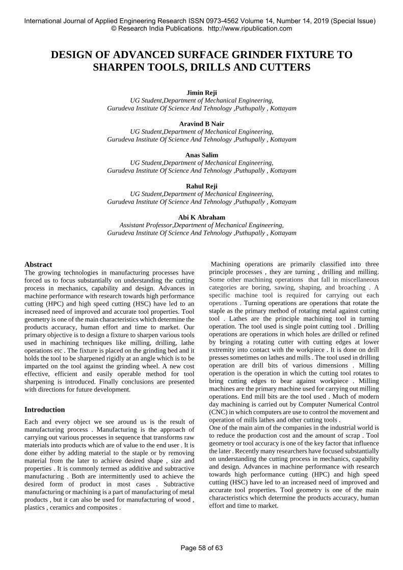
CAD model of fixture with single point cutting tool
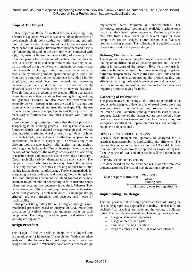
CAD model of Fixture with collet holder
Components of Fixture
The fixture has mainly eight components. They are:
COLLET HOLDER
It is made up of mild steel. A collet holder rigidly holds the
collet in which the drilling and milling bits to be sharpened is
held. The tightening of cover of the collet holder causes the
collet to be fixed inside. The collet holder have the provision
of space for correct seating of collet and is provided with
external threading.Internal threading is provided on the collet
holder cover and its tightening causses the rigid holding of
collet inside the collet holder.
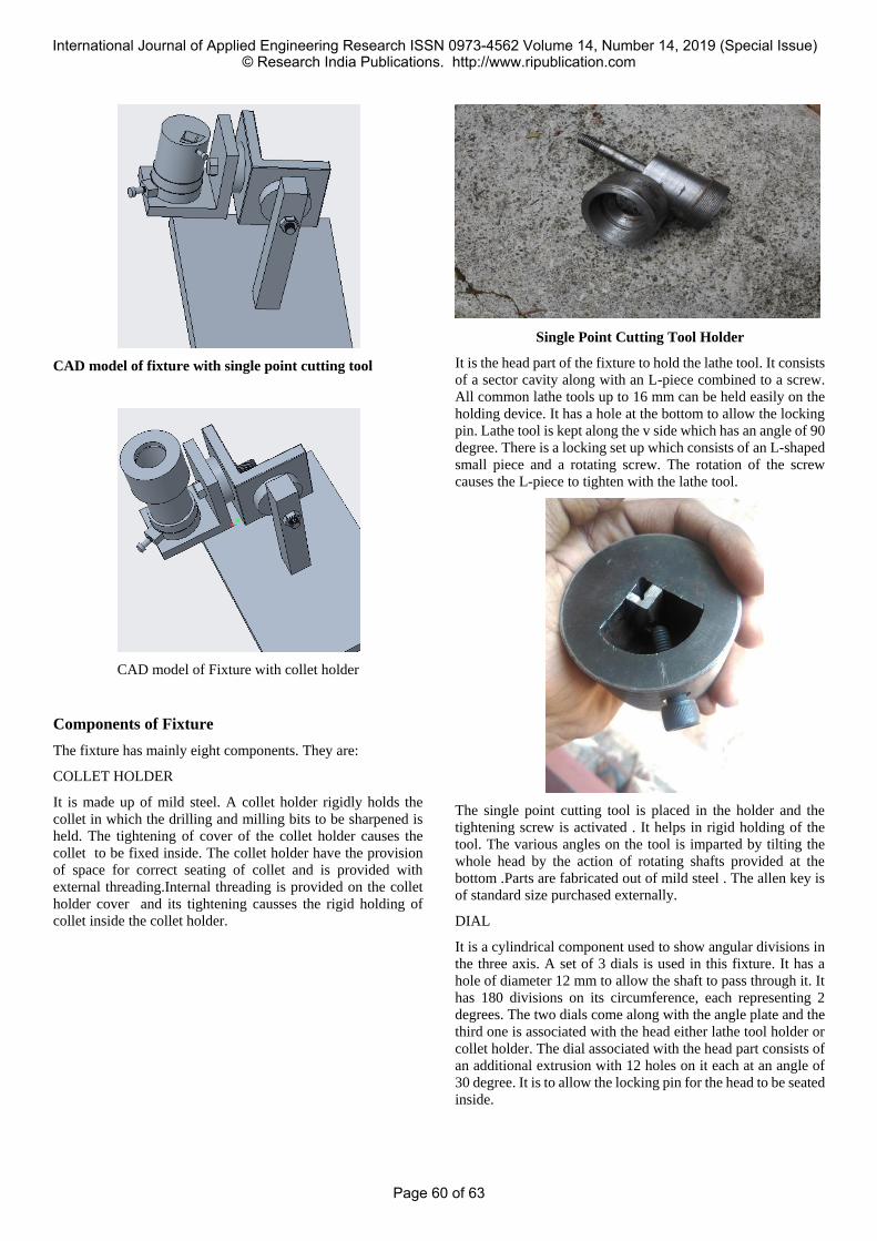
Single Point Cutting Tool Holder
It is the head part of the fixture to hold the lathe tool. It consists
of a sector cavity along with an L-piece combined to a screw.
All common lathe tools up to 16 mm can be held easily on the
holding device. It has a hole at the bottom to allow the locking
pin. Lathe tool is kept along the v side which has an angle of 90
degree. There is a locking set up which consists of an L-shaped
small piece and a rotating screw. The rotation of the screw
causes the L-piece to tighten with the lathe tool.
The single point cutting tool is placed in the holder and the
tightening screw is activated . It helps in rigid holding of the
tool. The various angles on the tool is imparted by tilting the
whole head by the action of rotating shafts provided at the
bottom .Parts are fabricated out of mild steel . The allen key is
of standard size purchased externally.
DIAL
It is a cylindrical component used to show angular divisions in
the three axis. A set of 3 dials is used in this fixture. It has a
hole of diameter 12 mm to allow the shaft to pass through it. It
has 180 divisions on its circumference, each representing 2
degrees. The two dials come along with the angle plate and the
third one is associated with the head either lathe tool holder or
collet holder. The dial associated with the head part consists of
an additional extrusion with 12 holes on it each at an angle of
30 degree. It is to allow the locking pin for the head to be seated
inside.
International Journal of Applied Engineering Research ISSN 0973-4562 Volume 14, Number 14, 2019 (Special Issue) © Research India Publications. http://www.ripublication.com
Page 60 of 63

The part is fabricated out of mild steel. The operations involved
are facing , turning , cutting etc. The cavity for dial locking pin
is formed by drilling. The marking are made using a milling
machine.
ANGLE PLATES
It is one of the major part of the component that conveys the
rotation taking place along one plane to the other. It is made up
of flat plate bar. Both ends of the L-shaped component is
machined to a semi circle to avoid their intersection. Holes of
12mm are drilled to let insertion of shaft. It has a marking on it
calibrated to zero degree and the rotation of angle plates is
measured by using the dial next to it. The loosening of screw
on the shaft creates the provision for rotation of angle plates
that imparts required angle for the head part . We knows the
angle which is to be incorporated on the tool. Initially the tool
is at zero degree. After loosening the screw the required angle
of rotation is done and then the screw is tightened .It uses a
simple technique similar to the insertion of angle on a lathe tool
past.
It is fabricated out of mild steel flat plate. Two pieces are
welded at 90° and holes for allowing the insertion of shaft is
drilled at a dimension of 12mm. The sharp ends are grinded to
avoid their intersection and impart aesthetic approach.
DIAL LOCKING ASSEMBLY
The dial adjacent to the head consisting of either collet holder
or lathe tool holder requires a locking assembly .A spring screw
set up is used here . The internal shaft moves in and out on
exerting force which allows the correct positioning of pin in the
holes drilled at equal intervals on the bottom of the dial . The
spring holds the dial in position . Once the pin is made to fall
inside one of the hole the head is rigidly fixed in that position
due to the spring force . A force greater than the spring force
should be provided to remove the locking or for movement of
head part . The shaft is pulled over to do the later.
The outer ring is made up of mild steel and the pin is fabricated
using silver rod . The operations carried out in its
manufacturing are welding , cutting , grinding , drilling etc .The
removal of pin and spring is possible by loosening the screw
provided at its ends .
SHAFT
Bolt of standard size M12 is used as the shaft and is locked
using a nut.Two similar shafts of diameter 12mm is used for the
components along the x and y axis.For the head part another
shaft of 12 mm with an increased length having limited
threaded section is fabricated.The shaft holds all the
components on it without any bending or deformation.
It is purchased from outside and is directly used as the shaft. It
is made up of mild steel. It is capable for bearing much higher
loads as seen in practical applications. The loosening of nut is
done for rotating the parts on the shaft. After setting the
required angle the nut is tightened.
BASE
It is the part that rests on the grinding bed. It holds the whole
weight of the fixture and restricts all movements. It is
accurately fabricated and finished as slight error in the base
could cause larger defects. It bears all the forces caused due to
cutting, bending torque, weight of the components etc . The
weight of the base is kept to minimum so as to allow easy
handling of fixture. The surface area of base of the fixture in
contact with the grinding bed is increased so as to provide high
magnetic holding force. The height of the base is maintained
between a range as there is a maximum distance between the
wheel and the bed above which it could not be raised. The
International Journal of Applied Engineering Research ISSN 0973-4562 Volume 14, Number 14, 2019 (Special Issue) © Research India Publications. http://www.ripublication.com
Page 61 of 63
height must be above a value of 150mm to allow free
movement of parts on rotation about the axes.
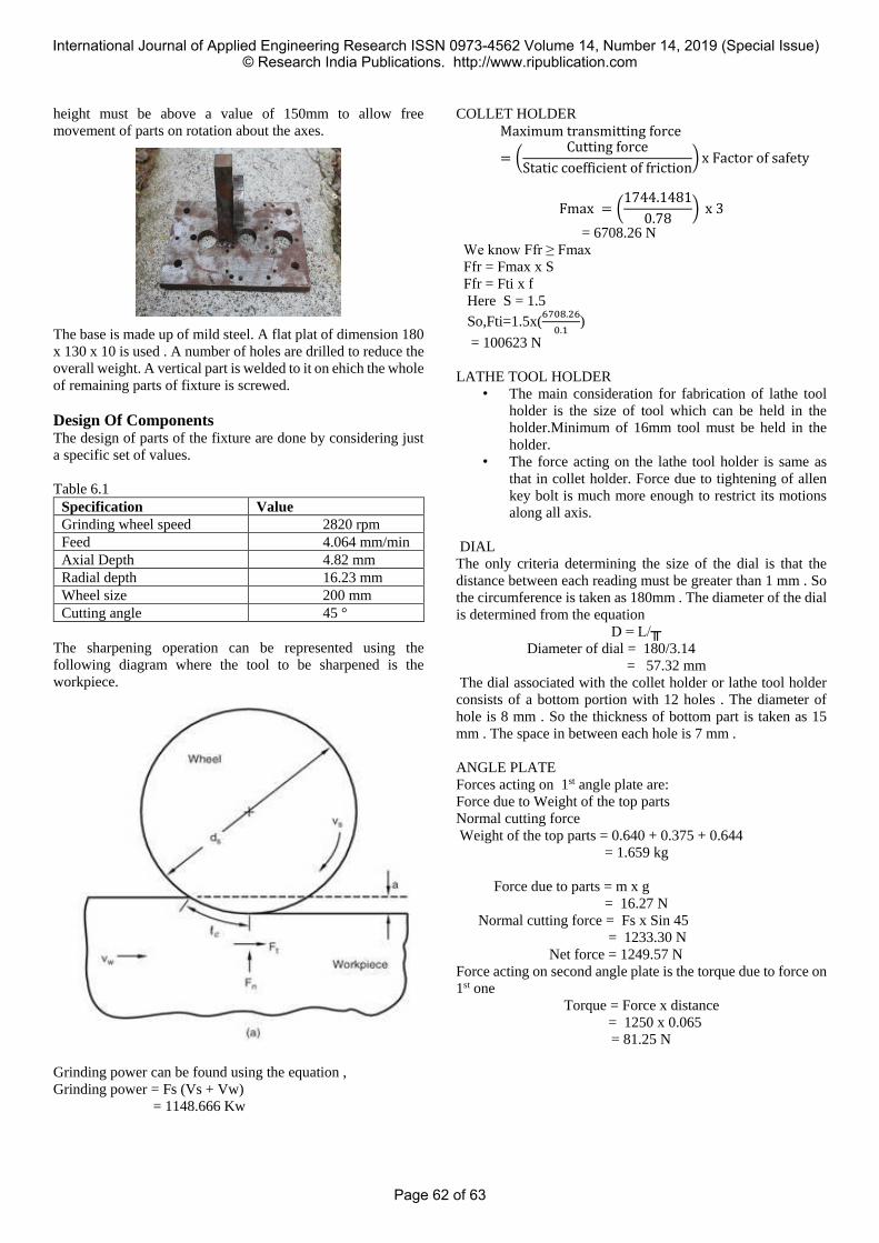
The base is made up of mild steel. A flat plat of dimension 180
x 130 x 10 is used . A number of holes are drilled to reduce the
overall weight. A vertical part is welded to it on ehich the whole
of remaining parts of fixture is screwed.
Design Of Components The design of parts of the fixture are done by considering just
a specific set of values.
Table 6.1
Specification Value
Grinding wheel speed 2820 rpm
Feed 4.064 mm/min
Axial Depth 4.82 mm
Radial depth 16.23 mm
Wheel size 200 mm
Cutting angle 45 °
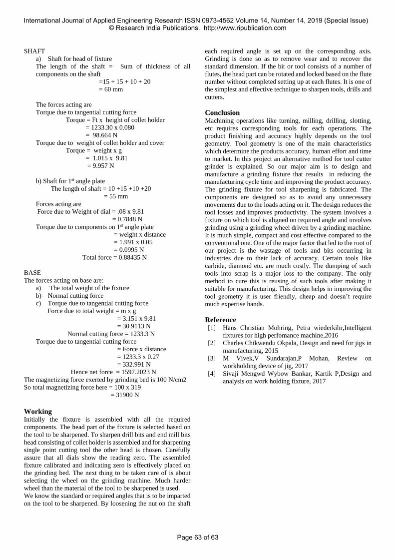
The sharpening operation can be represented using the
following diagram where the tool to be sharpened is the
workpiece.
Grinding power can be found using the equation ,
Grinding power = Fs (Vs + Vw)
= 1148.666 Kw
COLLET HOLDER
Maximum transmitting force
= (Cutting force
Static coefficient of friction) x Factor of safety
Fmax = (1744.1481
0.78) x 3
= 6708.26 N
We know Ffr ≥ Fmax
Ffr = Fmax x S
Ffr = Fti x f
Here S = 1.5
So,Fti=1.5x(6708.26
0.1)
= 100623 N
LATHE TOOL HOLDER
• The main consideration for fabrication of lathe tool
holder is the size of tool which can be held in the
holder.Minimum of 16mm tool must be held in the
holder.
• The force acting on the lathe tool holder is same as
that in collet holder. Force due to tightening of allen
key bolt is much more enough to restrict its motions
along all axis.
DIAL
The only criteria determining the size of the dial is that the
distance between each reading must be greater than 1 mm . So
the circumference is taken as 180mm . The diameter of the dial
is determined from the equation
D = L/╥
Diameter of dial = 180/3.14
= 57.32 mm
The dial associated with the collet holder or lathe tool holder
consists of a bottom portion with 12 holes . The diameter of
hole is 8 mm . So the thickness of bottom part is taken as 15
mm . The space in between each hole is 7 mm .
ANGLE PLATE
Forces acting on 1st angle plate are:
Force due to Weight of the top parts
Normal cutting force
Weight of the top parts = 0.640 + 0.375 + 0.644
= 1.659 kg
Force due to parts = m x g
= 16.27 N
Normal cutting force = Fs x Sin 45
= 1233.30 N
Net force = 1249.57 N
Force acting on second angle plate is the torque due to force on
1st one
Torque = Force x distance
= 1250 x 0.065
= 81.25 N
International Journal of Applied Engineering Research ISSN 0973-4562 Volume 14, Number 14, 2019 (Special Issue) © Research India Publications. http://www.ripublication.com
Page 62 of 63
SHAFT
a) Shaft for head of fixture
The length of the shaft = Sum of thickness of all
components on the shaft
=15 + 15 + 10 + 20
= 60 mm
The forces acting are
Torque due to tangential cutting force
Torque = Ft x height of collet holder
= 1233.30 x 0.080
= 98.664 N
Torque due to weight of collet holder and cover
Torque = weight x g
= 1.015 x 9.81
= 9.957 N
b) Shaft for 1st angle plate
The length of shaft = 10 +15 +10 +20
= 55 mm
Forces acting are
Force due to Weight of dial = .08 x 9.81
= 0.7848 N
Torque due to components on 1st angle plate
= weight x distance
= 1.991 x 0.05
= 0.0995 N
Total force = 0.88435 N
BASE
The forces acting on base are:
a) The total weight of the fixture
b) Normal cutting force
c) Torque due to tangential cutting force
Force due to total weight = m x g
= 3.151 x 9.81
= 30.9113 N
Normal cutting force = 1233.3 N
Torque due to tangential cutting force
= Force x distance
= 1233.3 x 0.27
= 332.991 N
Hence net force = 1597.2023 N
The magnetizing force exerted by grinding bed is 100 N/cm2
So total magnetizing force here = 100 x 319
= 31900 N
Working
Initially the fixture is assembled with all the required
components. The head part of the fixture is selected based on
the tool to be sharpened. To sharpen drill bits and end mill bits
head consisting of collet holder is assembled and for sharpening
single point cutting tool the other head is chosen. Carefully
assure that all dials show the reading zero. The assembled
fixture calibrated and indicating zero is effectively placed on
the grinding bed. The next thing to be taken care of is about
selecting the wheel on the grinding machine. Much harder
wheel than the material of the tool to be sharpened is used.
We know the standard or required angles that is to be imparted
on the tool to be sharpened. By loosening the nut on the shaft
each required angle is set up on the corresponding axis.
Grinding is done so as to remove wear and to recover the
standard dimension. If the bit or tool consists of a number of
flutes, the head part can be rotated and locked based on the flute
number without completed setting up at each flutes. It is one of
the simplest and effective technique to sharpen tools, drills and
cutters.
Conclusion Machining operations like turning, milling, drilling, slotting,
etc requires corresponding tools for each operations. The
product finishing and accuracy highly depends on the tool
geometry. Tool geometry is one of the main characteristics
which determine the products accuracy, human effort and time
to market. In this project an alternative method for tool cutter
grinder is explained. So our major aim is to design and
manufacture a grinding fixture that results in reducing the
manufacturing cycle time and improving the product accuracy.
The grinding fixture for tool sharpening is fabricated. The
components are designed so as to avoid any unnecessary
movements due to the loads acting on it. The design reduces the
tool losses and improves productivity. The system involves a
fixture on which tool is aligned on required angle and involves
grinding using a grinding wheel driven by a grinding machine.
It is much simple, compact and cost effective compared to the
conventional one. One of the major factor that led to the root of
our project is the wastage of tools and bits occurring in
industries due to their lack of accuracy. Certain tools like
carbide, diamond etc. are much costly. The dumping of such
tools into scrap is a major loss to the company. The only
method to cure this is reusing of such tools after making it
suitable for manufacturing. This design helps in improving the
tool geometry it is user friendly, cheap and doesn’t require
much expertise hands.
Reference [1] Hans Christian Mohring, Petra wiederkihr,Intelligent
fixtures for high perfomance machine,2016
[2] Charles Chikwendu Okpala, Design and need for jigs in
manufacturing, 2015
[3] M Vivek,V Sundarajan,P Mohan, Review on
workholding device of jig, 2017
[4] Sivaji Mengwd Wybow Bankar, Kartik P,Design and
analysis on work holding fixture, 2017
International Journal of Applied Engineering Research ISSN 0973-4562 Volume 14, Number 14, 2019 (Special Issue) © Research India Publications. http://www.ripublication.com
Page 63 of 63