Embed Size (px)
Citation preview

Abstract— Kees de Blok proposed a “hybrid configuration”
travelling wave thermoacoustic engine and his prototype using
atmosphere air as the working gas achieved an onset
temperature difference as low as 65 K. However, no further
research work has been reported on this type of thermoacoustic
engine to reveal whether this type of engine can achieve higher
efficiency, or how to couple it with acoustic loads such as a
thermoacoustic cooler or a linear alternator. This paper
investigates these problems based on a series of comprehensive
numerical simulations. A numerical model is established using
the reported parameters and validated by the published data.
The physical principles behind the design were then understood
in detail. The validated model is then modified and an acoustic
load (i.e., a thermoacoustic cooler) is installed to the engine.
The simulation results show that the engine can achieve about
46.5% of the Carnot efficiency and the cooler can achieve
39.6% of Carnot COP. The research of this paper shows that
this new engine configuration has the potential to achieve high
efficiency.
Key words— thermoacoustic engine, travelling wave, cooler,
resonator
I. INTRODUCTION
hermoacoustic engines deals with the thermodynamic
conversion between thermal energy and acoustic work
(i.e. a p-v work). In 1979, Ceperley [1, 2] pointed out that,
when the travelling sound wave propagates through a
regenerator with positive temperature gradient along the
direction of sound wave propagation, the gas parcel within
the regenerator experiences a Stirling-like thermodynamic
cycle, and therefore a travelling wave thermoacoustic engine
can be built. Yazaki et al. [4] demonstrated a practical
travelling-wave thermoacoustic engine for the first time,
which however had a relative low efficiency because of the
large viscous losses resulting from high acoustic velocities in
the regenerator and the resonator feedback. Backhaus and
Swift [5] later invented a travelling wave thermoacoustic
Stirling engine. The thermoacoustic core was placed within a
torus with a length much shorter than the acoustic
wavelength at the operating frequency. A long standing-
wave resonator was connected to this torus just after the
secondary ambient heat exchanger to provide the resonance.
Author Ali Al-Kayiem Support from the Ministry of Higher of Education/
Babylon University in Iraq (No. 553 Iraqi cultural attaché). Ali Al-Kayiem
is with the School of Engineering, University of Glasgow, Glasgow,
Scotland, United Kingdom; e-mail: [email protected]
*Corresponding author: Zhibin Yu is with the School of Engineering,
University of Glasgow, Glasgow, Scotland, United Kingdom;e-
mail:[email protected]
Backhaus’ engine achieved a thermal efficiency of 30%,
equivalent to 41% of the theoretical Carnot efficiency. Tijani
and Spoelstra [6] later designed and built a similar
thermoacoustic Stirling heat engine, and achieved 49% of
Carnot efficiency.
Kees de Blok has made a series of efforts on the
development of travelling wave thermoacoustic engines [7,
8, 10]. He proposed a bypass type traveling-wave
thermoacoustic engine in 1998, which operates on similar
principles to the thermoacoustic Stirling engine developed
by Backhaus [5]. In 2008, he proposed a hybrid
configuration for travelling wave thermoacoustic engine,
which lowered the onset temperature difference to about 65
K and demonstrated a great potential for utilising low
temperature heat sources such as solar energy and waste heat
sources [7]. Later, he also demonstrated multistage looped
type travelling wave thermoacoustic engines, and their
applications to drive coolers and linear alternators [3]. It was
pointed out that, in theory an arbitrary number of
thermoacoustic engine units can be connected in series
within one looped tube resonator. However, the 4-stage
configuration has a unique advantage because the four
engine units can be placed with equal distance within the
loop so that the distance between two adjacent stages is
about one quarter of the wave length. In this way, the
reflections due to impedance anomalies tend to compensate
each other. Therefore, near travelling wave conditions can
be achieved within the regenerators and feedback pipe.
Essentially, the various engine types mentioned above all
work on the same thermodynamic principle. The different
configurations mainly lie in the different designs of acoustic
resonator. The resonator provides the acoustic resonance to
facilitate the gas parcel to complete the thermodynamic
cycle with the regenerator. Depending on the characteristics
of the acoustic field within the resonator, it can be a standing
wave or travelling wave resonator. Backhaus’
thermoacoustic Stirling engine used a quarter-wave-length
standing wave resonator. Yazaki’s engine and de Blok’s’
multistage engine used a one-wave-length travelling wave
resonator. De Blok’s’ hybrid configuration engine used a
travelling wave resonator with a bypass.
The design principle of a thermoacoustic engine is to
maximize the acoustic power generation within the
thermoacoustic core, while minimising the acoustic loss
within the acoustic resonator. The travelling wave resonator
is superior to standing wave one as its acoustic loss is much
lower. In a standing wave resonator, there is a positive
interference between two traveling waves, so that the
pressure and velocity local amplitudes can be nearly twice
Design of a Traveling Wave Thermoacoustic
Engine Driven Cooler with Hybrid
Configuration
Ali Al-Kayiem and Zhibin Yu*
T
Proceedings of the World Congress on Engineering 2014 Vol II, WCE 2014, July 2 - 4, 2014, London, U.K.
ISBN: 978-988-19253-5-0 ISSN: 2078-0958 (Print); ISSN: 2078-0966 (Online)
WCE 2014

the amplitudes in the initial traveling wave generated in the
engine, resulting in high acoustic losses [3].
As schematically shown in Fig.1, the hybrid configuration
thermoacoustic engine proposed by de Blok has achieved a
very low onset temperature difference. However, there is no
further research on this type of engine to clarify whether this
type of engine can potentially achieve high thermodynamic
efficiency compared with other type of travelling wave
thermoacoustic engines. It also remains unknown how the
acoustic load can be installed to such engine without altering
the delicately designed acoustic field.
This paper aims to answer some of these questions based
on a series of comprehensive simulations. Firstly, a
numerical model is established based on the information
reported in the references, and then the model is validated
against reported experimental data. Once the model is
validated, the design principle is fully understood. The
model is then modified and acoustic load is installed to the
engine carefully without breaking the design principles. In
this way, a hybrid configuration thermoacoustic engine
driven cooler will be modelled to investigate how high an
engine efficiency can be obtained, and how the acoustic load
(i.e. cooler) can be coupled to the engine. The results are
presented and discussed in detail in this paper.
II. MODEL AND VALIDATION
The hybrid configuration thermoacoustic engine proto type
reported by de Blok is modelled using DeltaEC software
(Design Environment for Low-amplitude ThermoAcoustic
Energy Conversion). [9] As shown in Figure 1, this engine
has two stages, and each stage has a hot heat exchange
(HHX), regenerator (REG), and ambient heat exchanger
(AHX).
Fig. 1. Schematic diagram of the bypass geometry.
The other components of the system are described as:
feedback pipe (0), bypass pipe (1), compliance (3), inertance
tube (2), two regenerators, two ambient heat exchanges and
two hot heat exchanges. Most of the dimensions were
obtained from the reference and listed in Table I, and some
dimensions were estimated according to our understanding
when they are not directly available from the reference [8].
The working gas is air at atmosphere pressure, and the
operating frequency is 117 Hz. The simulations results are
shown as Figures 2 -5.
*These parameters were not reported in the reference, and are estimated.
Fig. 2. Distribution of the amplitude of acoustic pressure along the loop.
Fig. 3. Distribution of the acoustic power along the loop.
Figure 2 shows the pressure amplitude along the engine
loop. The pressure amplitude in the resonator is 3430 Pa and
the Standing Wave Ratio (SWR) is about 1.2. In the present
simulation, the pressure amplitude is set the same as 3430 Pa
in the resonator and the obtained SWR is 1.5. Table II shows
the comparison between the simulated results and the
reported experimental data. The experimental results agree
Table I. Dimensions of de Blok’ prototype [8].
Part Diameter
(m)
Length
(mm)
Rh
(um)
Porosity
AHX1 0.123 0.56 40* 0.8
REG1 0.123 1.58 150* 0.74
HHX1 0.123 0.56 120* 0.8
AHX2 0.123 0.56 120* 0.8
REG2 0.123 1.58 130* 0.74
HHX2 0.123 0.56 120* 0.8
Part Diameter (m) Length (m)
Bypass 0.075 1*
Resonator 0.075 1.75*
Inertance 0.05 1.2*
Compliance 0.11 0.127*
Duct between two stages 0.123 0.03
Table II. Comparison of pressure amplitude at different location.
Location Measurement (kpa) Present simulation (kpa)
REG section 5.22 5.2
Resonator 3.54 3.6
Bypass 2.77 2.7
Compliance 4.36 4.7
Inertance 1.87 3.4
Proceedings of the World Congress on Engineering 2014 Vol II, WCE 2014, July 2 - 4, 2014, London, U.K.
ISBN: 978-988-19253-5-0 ISSN: 2078-0958 (Print); ISSN: 2078-0966 (Online)
WCE 2014

with the simulation very well, except the pressure amplitude
in the inertance tube.
Figure 3 shows the acoustic power distribution along the
loop system. The simulation starts from the junction of the
bypass and engine branch (X=0). The total acoustic power is
about 80 W, and it splits into two parts. One part flows into
the bypass and is about 47 W, and the other part is about 33
W and flows into the compliance. The two engine stages
slightly amplify the acoustic power to 37 W, which then
joins with the acoustic power flow from the bypass pipe. The
total power is now about 82 W and flows into the feedback
pipe. The feedback pipe transports the acoustic power back
to beginning (X=0).
Acoustic power has been measured at two locations as
shown in Fig. 1 [8]. The first location P1 lies in the centre of
inertance tube and the second location P2 is at the beginning
of the feedback pipe. The measurements showed that the
acoustic power flow is about 35 W at location P1 and about
78 W at location P2. In the present model, the simulations
show an acoustic power of 32 W at location P1 and about 79
W at location P2. The simulation results agree with the
measurements very well.
Fig. 4. Distribution of the normalized acoustic impedance along the
loop.
Fig. 5. Phase angle θ between pressure and velocity oscillations along
loop.
The design philosophy for this type of engine is that, the
acoustic impedance at the end of the feedback pipe (X=0)
should be tuned to the characteristic impedance ρma of a
pure travelling wave field, so that the reflection can be
cancelled. This is very similar to the impedance match
technique of a microwave network. In this way, the acoustic
power can be transmitted through the feedback pipe with the
least losses. To check this design principle, the normalised
impedance has been extracted from the simulation results
and shown as Fig. 4. It can be found that the acoustic
impedance at the end of feedback pipe (X=3.1 m) is about
0.7ρma, which is very close to 1 as expected. However, due
to the lack of some dimensions, the actual impedance
measured by de Blok is closer to 1. Notwithstanding, the
present model has captured the physics of the prototype.
The normalised impedance increases along the
compliance duct from 2.45 to 4, and then sharply drops to
0.7 at the beginning of the inertance tube due to the sudden
change of cross sectional area. The normalised impedance in
the regenerator is estimated to be around 3 in de Blok’s
prototype but no measurement is provided, while it is about
5 according to the simulation of the present model. |Z|/ρma is
in the range 0.6~1.4 within the feedback pipe, which is not
very far from the ideal value of 1 as expected. It is also
interesting that |Z|/ρma is about 1 throughout the bypass,
which indicates that a near travelling wave condition has
been achieved in the bypass as expected.
To further understand the design principle of this type of
travelling wave thermoacoustic engine the phase difference
between the pressure and velocity oscillation has been
extracted and showed in Fig.5. From Fig. 5, it can be found
that the by-pass and the feed-back pipe has a phase angle in
the range -20°<ϴ<20°, and therefore a near travelling wave
field has been achieved in these two main components. From
the acoustic viewpoint, these two components actually form
the acoustic resonator for the engine. The onset temperature
difference is significantly reduced because the travelling
wave acoustic resonator dissipates much less acoustic power
compared with the standing wave resonator that was used in
Backhaus’ thermoacoustic engine. The two thermoacoustic
engine stages also work at a near travelling wave condition. However, there is a spike shown in Figure 5 (x=1.28~1.3
m), where is at the end of the inertance tube. This is due to
the sudden change in area from a small inertance area to a
big engine section. The compliance of the engine section
shifted the phase significantly.
III. APPLICATION TO A THERMALLY DRIVEN COOLER
The validation of the model offered us the confidence to
apply this new configuration travelling wave thermoacoustic
engine to some actual applications. In this paper, we aim to
develop a thermally driven thermoacoustic refrigerator with
an operating temperature about -20 ◦C. The heat source is in
a temperature range 200-300 ◦C.
The whole system has a similar configure to that shown in
Figure 1. However, the second stage engine unit is replaced
by a cooler stage, and the regenerator of the engine stage has
been increased from 1.58 to 20 mm to utilise a relatively
high temperature difference. The working gas is changed to
pressurised nitrogen with a pressure of 10 bar. The operating
frequency is about 75 Hz. The maximum pressure amplitude
is about 85 kPa, and therefore the relative pressure
amplitude relative to the men pressure is about 8.5% which
is in the range in which the DeltaEC computing programme
can be used.
Proceedings of the World Congress on Engineering 2014 Vol II, WCE 2014, July 2 - 4, 2014, London, U.K.
ISBN: 978-988-19253-5-0 ISSN: 2078-0958 (Print); ISSN: 2078-0966 (Online)
WCE 2014

The dimensions of the main components are summarized
and listed in Table III. The regenerators have the geometric
configuration of a mesh screen. Following the same design
as de Blok’s prototype, the heat exchangers have the
geometric configuration of a woven screen, which is ideal
for simulations. It should be noted that, it is hard to
manufacture such type of heat exchangers, and therefore
conventional designs such as shell-and-tube heat exchanger
will be used for practical designs. In this paper, we mainly
focus on the numerical analysis, and therefore it is more
convenient to use the same type of heat exchangers as those
in de Blok’s prototype. In table III, AHX1, REG1 and
HHX1 form the thermoacoustic core for the engine, while
AHX2, REG2 and CHX2 form the thermoacoustic core for
the cooler. In de Blok’s prototype, the gap between the two
engine stages is about 3 cm to act as a thermal buffer tube as
his hot heat exchanger has a temperature less than 160 ◦C. In
our system, the temperature difference between HHX1 and
AHX2 is more than 200 ◦C, and therefore, a long thermal
buffer tube with a length of 12 cm is required to reduce the
heat losses. The optimisation processes are very tedious and are
omitted in this paper. The results based on the final model
after the optimisation have been presented here, while some
optimisation steps will also be presented and discussed later
in this section.
The final simulation results are summarised and listed in
Table IV. The heat source temperature (i.e. the solid
temperature at HHX1) is 260 ◦C, and heat sink temperature
(i.e., the solid temperature of AHX1 and AHX2) is 28 ◦C.
The net acoustic power production from the engine unit is
the difference of the inlet and lout let acoustic power, and is
about 394 W. The net acoustic power consumed by the
cooler is 300 W. The heat input to the engine’s hot heat
exchanger is 1480 W. The engine efficiency ηe is defined as
the ratio of the acoustic power consumed by the cooler over
the heat input to the engine, and there is 20.2%, which is
about 46.5% of the Carnot efficiency at this temperature
range. The cooler removes 639 W heat at -19 ◦C, and rejects
it at 28 ◦C. the cooler’s coefficient of performance (COP) is
defined as the ratio of the heat absorbed at CHX2 over the
acoustic power it consumes, and therefore is about 2.13,
which is 39.6% of the Carnot COP at this temperature range.
Fig. 6. Distribution of the amplitude of acoustic pressure along the loop.
Fig. 7. Distribution of the amplitude of volumetric velocity along the loop.
To further investigate the implementation of the design
strategy of this type of thermoacoustic engine, the details of
Table III.Dimensions of integral system.
Part Diameter
(m)
Length
(m)
Rh
(um)
Porosity
REG1 0.138 0.02 40 0.77
REG2 0.138 0.02 40 0.77
AHX1 0.138 0.001 200 0.8
AHX2 0.138 0.001 200 0.8
HHX1 0.138 0.001 400 0.8
CHX2 0.138 0.001 600 0.8
Diameter (m) Length (m)
Bypass 0.0586 1.32
Resonator 0.0713 3.1478
Inertance 0.0422 1.35
Compliance 0.1009 0.124
Duct between two
stages
0.0504 0.12
Table IV.Summary of simulation results
Symbol Definition Unit Engine Cooler
Th Solid Temperature at
HHX1
◦C 260 --
Ta Solid Temperature at
AHX1&2
◦C 28 28
Tc Solid Temperature at
CHX2
◦C -- -19
Wa, in Acoustic power inlet W 700 1091
Wa, out Acoustic power outlet W 1093 792.3
Wa, net Net acoustic power
production (engine) or
consumption (cooler)
W 394 300
Qin,i Heat input to HHX
(engine) or CHX (cooler)
W 1480 639
ηe Engine Efficiency % 20.2
COP Coefficient of performance 2.13
ηCarnot Carnot Efficiency % 43.5
COPC Carnot COP 5.4
ηr Ratio to Carnot Efficiency % 46.5
COPR Ratio to Carnot COP % 39.6
Proceedings of the World Congress on Engineering 2014 Vol II, WCE 2014, July 2 - 4, 2014, London, U.K.
ISBN: 978-988-19253-5-0 ISSN: 2078-0958 (Print); ISSN: 2078-0966 (Online)
WCE 2014
the acoustic field within the whole system have been
extracted from the simulation results and shown in Figs 6-9.
In these figures, the solid line represents the results for
engine loop (engine branch and feedback pipe), and the
dashed line with symbols represent the results for bypass.
Figure 6 presents the acoustic pressure distribution along
the system. The maximum value of pressure is 88 kPa at the
engine core and the minimum value is 40 kPa at the middle
of the bypass pipe, so the Standing Wave Ratio (SWR) is
about 2.2 in the whole system, which is relative high
compared with de Blok’s prototype. This is mainly due the
regenerator length having been increased to 20 mm, and
therefore the flow resistance at the engine core is very high
and thus the acoustic reflection is high as well. However, the
situation in the feedback pipe is much better. The maximum
pressure amplitude is about 72 kPa, and the minimum
amplitude is about 50 kPa, so the SWR is about 1.2 which is
very close to the ideal travelling wave condition (SWR=1).
Figure 7 shows the distribution of the amplitude of
volumetric velocity along the system. It can be seen that the
bypass pipe shunts away two thirds of the volumetric
velocity at the end of the feedback pipe (X=0). This also
reflects the fact that almost two thirds of the acoustic power
(i.e., 1100 W) shunts to the bypass and only 727 W acoustic
flows back into the engine branch. There is a sharp increase
of volumetric velocity at the regenerator of engine stage due
to the steep temperature gradient along the regenerator. The
other sharp increase is due to the bypass pipe joining after
the end of cooler.
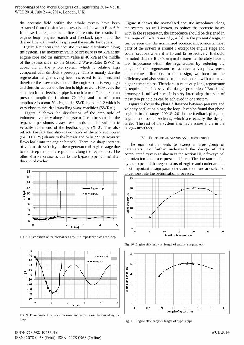
Fig. 8. Distribution of the normalized acoustic impedance along the loop.
Fig. 9. Phase angle θ between pressure and velocity oscillations along the
loop.
Figure 8 shows the normalised acoustic impedance along
the system. As well known, to reduce the acoustic losses
with in the regenerator, the impedance should be designed in
the range of 15-30 times of ρma [5]. In the present design, it
can be seen that the normalised acoustic impedance in most
parts of the system is around 1 except the engine stage and
cooler sections where it is 15 and 12 respectively. It should
be noted that de Blok’s original design deliberately have a
low impedance within the regenerators by reducing the
length of the regenerator to achieve a very low onset
temperature difference. In our design, we focus on the
efficiency and also want to use a heat source with a relative
higher temperature. Therefore, a relatively long regenerator
is required. In this way, the design principle of Backhaus’
prototype is utilised here. It is very interesting that both of
these two principles can be achieved in one system.
Figure 9 shows the phase difference between pressure and
velocity oscillation along the loop. It can be found that phase
angle is in the range -20°<ϴ<20° in the feedback pipe, and
engine and cooler sections, which are exactly the design
target. The rest of the system also has a phase angle in the
range -40°<ϴ<40°.
IV. FURTHER ANALYSIS AND DISCUSSION
The optimization needs to sweep a large group of
parameters. To further understand the design of this
complicated system as shown in the section III, a few typical
optimization steps are presented here. The inertance tube,
bypass pipe and the regenerators of engine and cooler are the
most important design parameters, and therefore are selected
to demonstrate the optimization processes.
Fig. 10. Engine efficiency vs. length of engine’s regenerator.
Fig. 11. Engine efficiency vs. length of bypass pipe.
Proceedings of the World Congress on Engineering 2014 Vol II, WCE 2014, July 2 - 4, 2014, London, U.K.
ISBN: 978-988-19253-5-0 ISSN: 2078-0958 (Print); ISSN: 2078-0966 (Online)
WCE 2014

Fig. 12. Engine efficiency vs. length of inertance tube.
Figure 10 shows effect of the length of the regenerator in
the engine unit on the engine efficiency. It can be found that
there is an optimal regenerator length of about 20 mm, which
is selected the final design as sumarrised in Table 3. The
regenerator length is very crucial. The flow reistance
increases when the length increases. For a given temperature
difference, the longer the length, the smaller thetemprature
gradient and consequently the less power production. On the
other hand, the shorter the length, the higher the conductive
heat loss through the regenerator, and therefore a tradeoff is
required.
Figure 11 shows the relationship between the engine
efficiency and length of the bypass length. The optimal
length is about 1.3 m and is chosen for final design.
Similarly, Fig. 12 shows the relationship between the length
of the inertance tube and engine efficiency. The optimal
length is about 1.3 m, and is selected for our final design.
The bypass and inertance tube are both the phase tuning
components. Their dimensions are very sensitive to achieve
the right phase and impedance within the engine and cooler
units and the feedback pipe.
According to the results shown in Section III and IV, it
can be found that the design strategies proposed by de Blok
and Backhaus can be both implemented in our travelling
wave thermoacoustic engine driven cooler system.
V. CONCLUSION AND FUTURE WORK
This paper presents a comprehensive numerical analysis
of hybrid configuration travelling wave thermoacoustic
engine driven cooler. The numerical model was first
established based on the reported prototype, and validated
by the published experimental data. The design principle is
then fully understood based on the analysis of the acoustic
field within the engine. The validated model is then applied
to design a thermally driven travelling wave thermoacoustic
cooler with hybrid configuration. The design principles
contained in the hybrid configuration have been
implemented in our design successfully although the design
objectives have been changed to achieve higher efficiency
and a cooler stage is introduced to the engine to act as
acoustic load. It is found that the design strategy for a high
efficiency engine can be incorporated in our design. The
research results showed that the new system can achieve
about 46.5% of the Carnot efficiency and 39.6% of the
Carnot COP. It can be expected that a better performance
can be achieved if the pressurised helium is used as the
working medium.
The prototype based on this design is currently under
construction. The experimental results will be obtained and
reported in the near future.
REFERENCES
[1] Ceperley PH: A pistonless Stirling engine-The traveling wave heat
engine. The Journal of the Acoustical Society of America 1979,
66:1508.
[2] Ceperley PH: Gain and efficiency of a short traveling wave heat
engine. The Journal of the Acoustical Society of America 1985,
77:1239.
[3] De Blok K: Novel 4-stage traveling wave thermoacoustic power
generator. In: Proceedings of ASME: 2010; 2010: 1-8.
[4] Yazaki T, Iwata A, Maekawa T, Tominaga A: Traveling wave
thermoacoustic engine in a looped tube. Physical Review Letters
1998, 81(15):3128.
[5] Backhaus, S. and Swift, G.W., A thermoacoustic- Stirling heat
engine: Detailed study, Journal of Acoustical Society of America,
vol 107(6), pp 3148-3166, 2000.
[6] Tijani, M. E. H. and Spoelstra, S. A high perfprmance
thermoacoustic engine. J. Appl. Phys. 110:093519, 2011.
[7] De Blok K, Systemen AT: Multi-stage traveling wave
thermoacoustics in practice. In: 19th International Congress on
Sound and Vibration Vilnius, Lithuania: International Institute of
Acoustics and Vibration (IIAV) and Vilnius University: 2012;
2012: 1-8.
[8] De Blok, K., Low operating temperature integral thermo acoustic
devices for solar cooling and waste heat recovery. Journal of the
Acoustical Society of America, 2008.123(5): p. 3541-3541.
[9] Ward B, Clark J, Swift G: Design environment for low-amplitude
thermoacoustic energy conversion, DELTAEC version 6.2: Users
guide. Los Alamos national laboratory 2008.
[10] De Blok CM. Thermoacoustic system Dutch patent. International
application number PCT/NL98/00515; 1998.
Proceedings of the World Congress on Engineering 2014 Vol II, WCE 2014, July 2 - 4, 2014, London, U.K.
ISBN: 978-988-19253-5-0 ISSN: 2078-0958 (Print); ISSN: 2078-0966 (Online)
WCE 2014