Embed Size (px)
Citation preview

Gabriel G. Gameiro Design of a test bench for the tilting bolster over the bogie
Lisbon: Instituto Superior Técnico, Master in Mechanical Engineering 2010/2011
1/10
DESIGN OF A TEST BENCH FOR THE TILTING BOLSTER OVER
THE BOGIE
Gabriel Gomes Gameiro (Extended abstract for MSc Thesis in Mechanical Engineering)
Instituto Superior Técnico, Technical University of Lisbon Lisboa, Portugal; email: [email protected]
Abstract
This paper present the design of a test bench for the tilting bolster over the bogie of the tilting
train CP 4000 of the company CP- Comboios de Portugal, E.P.E.
This test will serve to observe/measure the angle of inclination of the Load Bolster in relation
to the Tilting Bolster and the angles of the relative positions of the connecting rods.
The main objectives of this project are: 1) Design the test bench based on Standards/Codes of
the Mechanical Engineering Design; 2) Develop a new procedure/methodology for
observation/measurement the angles of the relative positions of the Bolsters and the connecting rods;
3) Analysis of manufacturing costs of the test bench.
This design was inspired by a need of the EMEF, S.A. Company to obtain one test bench that
is able to replace manual stay work methods. In this slow way of work it is used a coordinate measure
laser machine.
This test bench is composed by a support structure of the tilting bolster over the bogie and by
a work station that includes a hydraulics power unit to operate the hydraulic tilting cylinders to tilt the
Load Bolster and an electronic control unit to allow that one computer controls the hydraulic circuit and
measure the angles.
In the design of the supporting structure, there was a check of the forces involved and it was
made a structural analysis of the structure by means of method based on Eurocode 3 and a numerical
method (finite element method). In the hydraulic circuit and electronic unit, were selected all the
components that constitute it.
In conclusion, it is presented a test bench and a new methodology for measuring the angles
that satisfy the requirements and constraints specified in design.
Keywords: Test Bench, Train, Active Tilting, Structural Design, Eurocode 3, Oil-Hydraulic
Introduction Design Objective
The test bench for the tilting bolster over the bogie complements the equipment necessary to
EMEF company to ensure the quality of services provided in the maintenance of trains, once EMEF
company has a quality management system certified since the year 2000, currently as the norm NP
EN ISO 9001: 2008, covering all of its field of activity in all its establishments. In this case, this

Gabriel G. Gameiro Design of a test bench for the tilting bolster over the bogie
Lisbon: Instituto Superior Técnico, Master in Mechanical Engineering 2010/2011
2/10
equipment is used for testing the tilting bolster over the bogie of tilting train's CP 4000, property of the
company CP-Comboios de Portugal, E.P.E.
These test methods need improvement to reduce the time to perform testing and to make it
more efficient.
The aim of this project is a test bench that using the hydraulic cylinders of the same
bogie actuated by an oil hydraulic circuit. It simulates the movement of tilting train and checks
the relative positions of the four connecting rods, all through a computer that controls the oil
hydraulic circuit and constantly reads the angle between the Tilting Bolster and Load Bolster until
reaches 8 degrees. Once this value is obtained, the computer must verify the angular displacement of
the four rods and compare them with results given by the manufacturer (31 and 25 degrees).
Description of Test Performing Currently
At the moment, to measure the relative angles of the four connecting rods and the 8 degrees
between the Tilting Bolster and Load Bolster is used a coordinate measuring laser machine. The use
of this machine requires that the object to verify remains fixed, since it measures all the distances in
relation to its position. Subsequently the desired measure is computed.
With the requirement of having the object to measure remains fixed, the company has built a
structure to support the tilting bolster over the bogie, illustrated in figure 1.
Figure 1. The existing structure supporting the tilting bolster over the bogie
This structure is used to determinate the drilling stops signs of secondary suspension to fix the
assembly to the frame by 8 bolts.
This framework has some disadvantages:
• The procedure to set in place the structure and fix it with bolts is a time consuming
method and requires a meticulous work;
• Requires two operators, so that with a load lifting device, place the assembly on the
support and align the holes for the bolts are placed;
• Does not guarantee stability in order to prevent rollover in case of an accident.

Gabriel G. Gameiro Design of a test bench for the tilting bolster over the bogie
Lisbon: Instituto Superior Técnico, Master in Mechanical Engineering 2010/2011
3/10
First, to tilt the load Bolster 8 degrees, is used a crane and the angle between the Bolsters is
frequently measure till the specified angle is reached. Since this method was very time consuming,
some special tools were developed to make easy the all procedure.
Figure 2. Special tools used on the current tests
Project Specifications Project Requisites
i. The test bench must have the ability to tilt the Load Bolster 8 degrees in relation to the Tilting
Bolster.
ii. The test bench should be designed by the standards and codes of design.
iii. Use of standard components and profiles.
iv. The test bench should be as light as possible.
v. The test bench should be transportable.
vi. The test should be done automatically and in a short time.
vii. The console will also have manual control devices.
viii. The Unit Control should have an emergency stop device.
ix. The devices must be marked clearly and have good visibility.
x. Automatic issuing of test reports.
Project Constraints
i. The measurement of the angles should be as accurate as possible.
ii. The structure must support the tilting bolster over the bogie and remain stable in emergency
situations.
iii. The structure should be rigid.
iv. The minimum thickness of the components should be 4mm.

Gabriel G. Gameiro Design of a test bench for the tilting bolster over the bogie
Lisbon: Instituto Superior Técnico, Master in Mechanical Engineering 2010/2011
4/10
Solution Found
Support structure of the tilting bolster over the bogie
Figure 3. New structure obtained by the design
This structure meets all the requirements and constraints numbered in the previous
section and its main features are:
Weight: 178 Kg
Maximum width: 2000 mm
Maximum height: 1108 mm
Maximum length: 2444 mm
Constituted essentially by elements with profiles “UPN 80” e “L30x30x4”
Two eyebolts to lifting and to transport the structure.
Figure 4. New structure supporting the tilting bolster and the load bolster over the bogie
Item Description
1 Transverse Beam Base
2 Reinforcement Bar of stability
3 Support
4 Column
5 Lifting Eyebolt
6 Shell to fixed the supports
7 Reinforcement bar of transverse stiffness
8 Reinforcement bar of longitudinal stiffness
9 Longitudinal Beam Base
Table 1. Legend of figure 3
Load Bolster
Rod
Tilting Bolster

Gabriel G. Gameiro Design of a test bench for the tilting bolster over the bogie
Lisbon: Instituto Superior Técnico, Master in Mechanical Engineering 2010/2011
5/10
Control Unit
After performing the steps of the design of control unit, it was obtained one solution for the
portable table, one solution to hydraulic circuit and one solution to electronic circuit.
1. Portable Table:
Figure 5. Concept of the portable table with the control unit
This portable table has a lower compartment to place the hydraulic system (power group +
valve group), a base for placing a laptop computer and a set of buttons (emergency button and
buttons for manual operation of valves).
As the manufacture of this portable table will be more expensive than buying one in the
market that fits the same circumstances, it was opted for to buy the table which is illustrated in
Figure 6.
Figure 6. Portable table to buy
This table is manufactured by FACOM
® Company with the reference 2703PB and has the
following characteristics:
Dimensions (L x W x H): 1092 x 617 x 903 mm
Weight: 54,0 Kg
In this car will be adapted the hydraulic circuit, the electronic circuit and the buttons for manual
operation.

Gabriel G. Gameiro Design of a test bench for the tilting bolster over the bogie
Lisbon: Instituto Superior Técnico, Master in Mechanical Engineering 2010/2011
6/10
2. Electronic Circuit:
The electronic circuit is composed by one chain of measurement and one chain of actuation,
both connected to a Bus-Powered Multifunction DAQ for USB (NI USB-6008) for one computer with
software developed in LabView® control the test.
The chain of actuation is illustrated on the figure 7. It has two relays to act the hydraulic valves
because the DAQ doesn’t have electrical power to act the valves directly.
Figure 7. Chain of actuation
The chain of measurement is illustrated on the figure 8. It’s composed by one sensor
(inclinometer) that measure the require angle and the signal conditioning to convert the output signal
of inclinometer (4…20 mA) in the signal accepted by the DAQ (-10…10 V). The electronic circuit has
six chains of measurements. All of them have de the same signal conditioning but two have
inclinometers that measures angles between -15º and +15º for the plates and four have inclinometers
that measures angles between -45º and +45º for the rods. Figure 9 presents the signal conditioning.
Figure 8. Chain of measuring
Figure 9. Signal conditioning

Gabriel G. Gameiro Design of a test bench for the tilting bolster over the bogie
Lisbon: Instituto Superior Técnico, Master in Mechanical Engineering 2010/2011
7/10
3. Hydraulic Circuit:
The solution for the hydraulic circuit is shown in Figure 10.
Item Description
1 Reservoir - 40 L
2 Oil Filler Cap
3 Optical Level Indicator
4 Electrical Motor - 500W
5 Gear Pump
6 Return Filter
7 Pressure Filter
8 Pressure Gauge (0-60) bar
9 Pressure Relief Valve
10 Compensated Flow Control Valve
11 Solenoid Valve
12 Directional Valve Tray
13 Pilot Check Valve sandwich
14 Quick Coupler (3/8'')
15 Hydraulic Cylinder
Figure 10. Scheme of hydraulic circuit
Table 2. Legend of hydraulic circuit

Gabriel G. Gameiro Design of a test bench for the tilting bolster over the bogie
Lisbon: Instituto Superior Técnico, Master in Mechanical Engineering 2010/2011
8/10
Methodology
This project is divided into 2 parts: Design to supporting structure of the tilting bolster over the
bogie and the control unit with the hydraulic and electronic circuit.
Design of support structure of the tilting bolster over the bogie:
1. Concept generation:
In the first step, we surveyed the advantages and disadvantages of the existing support
structure in EMEF Company. As the structure had very significant disadvantages, it was
developed a new structure in order to supress these disadvantages.
2. Structural optimization and verification:
After generating the concept of the new structure, we proceeded to the structural optimization
and verification, first, by the analytical method following the advice of Eurocode 3 and later by
the numerical method (finite element method) using the software ANSYS ®. It was verified the
resistance of all the elements of the structure and the strength of the connections. In the end it
was compared the results of the two methods to check the reliability of the implemented
solutions.
Unit Control Project
The project consists of a portable table that supports a hydraulic power group and an
electronic circuit required to measure the angle and controller the hydraulic circuit.
1. Generation of the concept of the portable table:
To generate the concept of the portable table, was raised all the requirements and design
constraints imposed by EMEF Company. Once generated the concept, came to the conclusion
that it was all worthwhile purchase a portable table on the market that it is less expensive than
to manufacture one.
2. Project of the hydraulic circuit:
The amount of force needed to tilt the load plate was estimated that with the time of tilting, be
calculated the values of pressure and oil flow necessary to choose a pump and motor to
ensure the necessary strength in the cylinders. A supplier of hydraulic valves, filters and
other components of the hydraulic circuit was consulted in order to make a shopping list
and a cost estimation for the assembly of the hydraulic circuit.
3. Electronic circuit:
Another important step was the design of electronic circuitry of the test bench, the measuring
chain and the chain of actions controlled by a computer through a software created in
LabVIEW. Several catalogues from suppliers of electronic components were consulted to
identify the purchase, including the best sensors to use to measure the required
angles. Chains were designed to measure and action have been identified the major
Gabriel G. Gameiro Design of a test bench for the tilting bolster over the bogie
Lisbon: Instituto Superior Técnico, Master in Mechanical Engineering 2010/2011
9/10
components of electronic circuit and drew up a cost estimation for the manufacture of the
circuit.
RESULTS
In the structural verification by the analytical method, it´s used the following scheme forces, as
illustrated in figure 11.
Figure 11. Scheme of forces actuating on the structure
As a simplification, it was assumed that the components “c”, “e” and “f” are bars and the
components “a”, “b” and “d” are beams.
The value of the length “L” of the component “a” is obtained considering that the structure is
still stable when is tilted 45 degrees. This value equals 2000 millimetres.
The results obtained by this method are resumed on table 2.
Component Von Mises Stress Safety coefficient Allowable Stress
b 17.80 MPa 13.2
235 MPa
c 11.72 MPa 20.0
d 16.43 MPa 14.3
e 10.25 MPa 23
f 33.20 MPa 7.1
Table 3. Results of the von Mises Stress
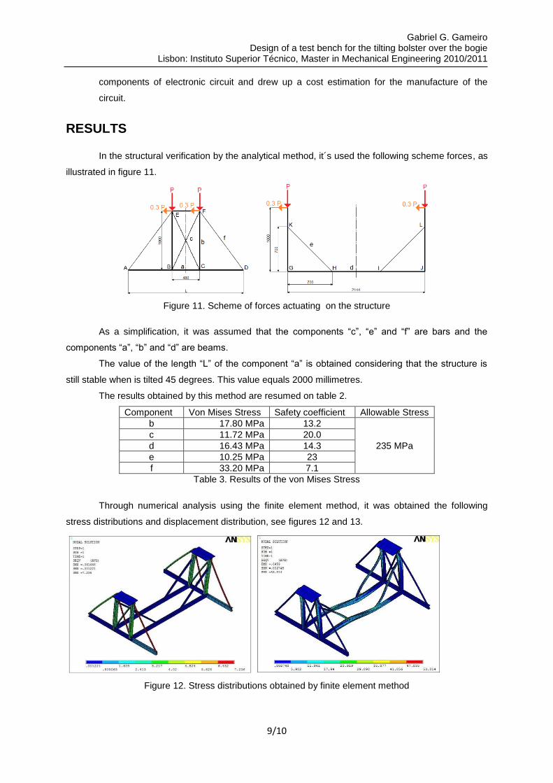
Through numerical analysis using the finite element method, it was obtained the following
stress distributions and displacement distribution, see figures 12 and 13.
Figure 12. Stress distributions obtained by finite element method

Gabriel G. Gameiro Design of a test bench for the tilting bolster over the bogie
Lisbon: Instituto Superior Técnico, Master in Mechanical Engineering 2010/2011
10/10
Figure 13. Displacement distribution
References
[1] NP EN 1990, Eurocódigo - Bases para o projecto de estruturas, Dezembro 2009
[2] NP EN 1993, Eurocódigo 3 – Projecto de estruturasde aço (partes 1 e 8), Março 2010
[3] Parlamento Europeu e do Conselho de 17 Maio de 2006, "Directiva 2006/42/CE," Jornal Oficial
da União Europeia de 9 de Junho de 2006, no. Directiva europeia relativa às máquinas.
[4] NP EN ISSO 13920:1996, Soldadura-Tolerâncias gerais para construção soldada, Março 2006
[5] Chagas. (2º Edição 2002) Manual Técnico de Produtos Siderúrgicos. [Online].
http://www.fachagas.pt/cache/bin/XPQWfpAXX56UzkZMyMbs1ZKU.pdf ( Abril de 2011)
[6] Grupo Ferpinta. Catálogo de Produtos Siderúrgicos [Online]
www.ferpinta.pt (Abril de 2011)
[7] J. N. Reddy, An Introduction To The Finite Element Method, Third Edition ed. McGraw-Hill
Science Engineering, December 2004.
[8] F. P. Beer and E. R. Jonhston, Mechanincs of Mateials. 4º edição, McGaw-Hill, 2006.
J. E. Shigley, C. R. Mischke, and R. G. Budynas, Mechenical Engineering Design. 8ª edição,
McGraw-Hill, 2008
[10] A. Silva, J. Dias, and L. Sousa, Desenho Técnico Moderno. 5ª Edição LIDEL, 2004.
[11] K. Ogata, Engenharia de Controle Moderno. 4ª Edição Pearson Prentice Hall, 2003
[12] MRA-Instrumentação. Catálogo de sensores [Online]
http://www.mra.pt/industria/produtos/instrumentacao/sensores-e-condicionadores-de-
sinal/sensores-de-posicionamento-angular---inclinometros/ (Junho de 2011)
[13] RS - Components. Distribuidor de componentes electrónicos [Online]
http://pt.rs-online.com/web/ (Junho de 2011)
[14] Legrand. Catálogo de componentes eléctricos [Online]
http://www.e-catalogue.legrandgroup.com/portugal/index.html?showTarif=true (Junho de 2011)
[15] Cudell®. Óleo-Hidráulica/Automação Industrial. Catálogo 2011
[16] Facom®. Catálogo Acções Especiais. 2010