Embed Size (px)
Citation preview

Design of a Modular Series Elastic Upgradeto a Robotics Actuator
Leandro Tome Martins1,2, Roberta de Mendonca Pretto1,2, Reinhard Gerndt2,and Rodrigo da Silva Guerra1(B)
1 Centro de Tecnologia, Univ. Federal de Santa Maria,Av. Roraima, Santa Maria, RS 1000, Brazil
{leandromartins,robertapretto}@mail.ufsm.br, [email protected] Department of Computer Sciences, Ostfalia University of Applied Sciences,
Am Exer 2, 38302 Wolfenbuttel, [email protected]
Abstract. In this article we present a compact and modular devicedesigned to allow a conventional stiff servo actuator to be easily upgradedinto a series elastic actuator (SEA). This is a low cost, open sourceand open hardware solution including mechanical CAD drawings, circuitschematics, board designs and firmware code. We present a completeoverview of the project as well as a case study where we show the devicebeing employed as an upgrade to add compliance to the knee joints ofan existing humanoid robot design.
Keywords: Series elastic actuator · Passive compliance
1 Introduction
Traditional robot manipulators, such as the ones designed for use in controlledindustrial settings, typically use very stiff joints, heavy and rigid structures andpowerful actuators. This is a practical way to isolate the influence of reactionforces caused by the load being manipulated. Nowadays, however, there has beenan increasing interest in the design of humanoid robots with compliant joints,capable of sharing their workspace with people. These joints allow for much saferand smoother human/robot interaction. Compliance also allows these joints toabsorb the energy of possible impacts, preventing gear damage. This energy canalso be released back into the environment in a controlled way, allowing forefficient dynamic walking or even jumping or running.
Most solutions for adding compliance into the design of robot joints can bedivided in two groups: (1) active (or simulated) compliance and (2) passive (orreal) compliance. Simulated compliance is achieved through software, by con-tinuously controlling the impedance of back-drivable electric motors (see forinstance [5]). Real or passive compliance is achieved through the employmentof real elastic elements, typically mechanical springs, in the design of the joints(see for instance [3]). For a while there has been some debate on the advantagesc© Springer International Publishing Switzerland 2015R.A.C. Bianchi et al. (Eds.): RoboCup 2014, LNAI 8992, pp. 701–708, 2015.DOI: 10.1007/978-3-319-18615-3 57
702 L.T. Martins et al.
and disadvantages of choosing active versus choosing passive compliance [10].However, with regard to human/robot interactions, there is consensus that pas-sive compliance ensures higher levels of safety. In a recent review [2] pointedto the importance of real compliance when building robotic arms for assistivetechnology.
This paper describes the design of an open-hardware/open-software SeriesElastic Actuator (SEA). All project files are made available at our group’s web-site [9]. A SEA is a type of actuator of passive compliance, where a spring isplaced in series with the rigid output thus granting elasticity to the system.Our designed device consists of software, firmware, electronics and a mechan-ical accessory that can be easily attached to the popular Dynamixel MX-28series servo actuator, manufactured by Robotis, transforming it into a SEA.This servo actuator was chosen as the base due to its wide popularity within theRoboCup community, however the general idea could be easily adapted to fitmost servo actuators of similar “RC-servo-style” design. The distinctive featuresof our design are its modularity and its versatility. Adding to these features thelow manufacturing cost, we believe this device has great potential for applicationwithin the RoboCup context and elsewhere.
The remainder of this work is organized as follows: Sect. 2 explains the maindetails regarding the design as well as the modelling of the SEA. Section 3 showssome data regarding the actual construction of the device and a robot upgradecase. Section 4 presents the closing remarks and outlines potential future work.
2 Methodology
This section is divided in three subsections: Subsect. 2.1 presents the mechanicaldesign of the SEA. Subsection 2.2 shows the electronics and firmware design.Subsection 2.3 gives a general idea of how the system is modelled as a whole.
2.1 Mechanics
The presented SEA follows a compact, modular, low cost mechanical design sim-ilar to that presented by Meyer et al. [8]. The device was designed such that itcould be easily adapted to existing robot projects, requiring as little change aspossible in the mechanics and electronics. It consists mainly of two parts that canrotate relative to each other, a set of two springs and a lid. See exploded view ofFig. 1. The bottom part consists of a disc with a wedge fixed to it. The middlepart is a solid cylinder with a C-shaped cut. Both bottom and middle parts aredesigned to fit on top of each other with the bottom wedge inside the C-shapedcut, forming two arc-shaped chambers, where helical springs are installed. Finallya lid is designed to fit on top of the cylinder, in order to keep the springs enclosedinside their respective chambers. Figure 2 shows the assembled device (withoutelectronics).
When a torque is applied, the bottom wedge slides through the C-shaped cut,expanding the spring of one chamber while compressing the spring in the other

Modular Series Elastic Upgrade to a Robotics Actuator 703
Fig. 1. CAD exploded view Fig. 2. Assembled SEA
chamber. In order to simplify their fixture design, both springs are designedto work always under compression. Notice that the angular range of motionin this elastic element does not need to be large because the servo actuatorcan dynamically extend this range, in a closed feedback loop. Focusing on theirspecific application Meyer et al. [8] used elastomer based, non-linear springs inan asymmetric design (compliant in one direction, stiff in the other). We focusedinstead in a lower cost, more general design, so we used linear helical springs ina symmetrical setup allowing compliance in both directions.
2.2 Electronics
In order to read the displacement of the springs we designed a magnetometer-based contact-less encoder circuit. A disc shaped, radial rare-earth magnet (typ-ically made of neodymium) is placed in the center of the assembly, right belowthe lid, but attached to the bottom part through a hole in the middle. The sensorboard is placed on the lid above it, allowing the magnetometer to measure thedirection of the generated magnetic field.
The chosen chip was the AS5043 manufactured by AMS, the same used insidethe Dynamixel MX-28R. This SIC offers a 10 bit DAC interface resulting in aresolution of 360 deg/210steps = 0.3515625 deg/step. There also is an analogoutput which could be combined with a custom external DAC to allow for evenhigher resolution, but for this version we used the 10 bit digital interface. Thecircuit was separated in two boards: (1) a small one just for the magnetometer,placed on top of the lid, and (2) an interface board to read the raw data fromthe sensor and communicate through RS485 protocol. Figures 3 and 4 show theschematics of the magnetometer and interface boards, respectively. To simplifythe development of the firmware, the interface board was made compatible withthe widely used Arduino standard [7].
The interface’s firmware was programmed to communicate using Dynamixel’sRS485 protocol. Each device can be programmed to receive a distinct id thusallowing them to communicate through the same bus as the original servo actua-tors, using the same protocol. This means no change is required in the electronics

704 L.T. Martins et al.
Fig. 3. Magnetometer circuit Fig. 4. Magnetometer’s interface circuit
of existing robot projects, except for the extra wires to include the additionaldevices to the existing communication bus. Torque measuring and control isachieved via software, as explained in the section below.
2.3 Modelling
The spring converts angular deformation into torque and vice-versa thus allowingus to transform a position control problem into a torque control problem. In thecase of a linear spring this relation is given by Hooke’s law, which here takes theform
τ = −k · α (1)
where τ is the torque, k is the linear spring stiffness constant and α is the angulardisplacement of the device.
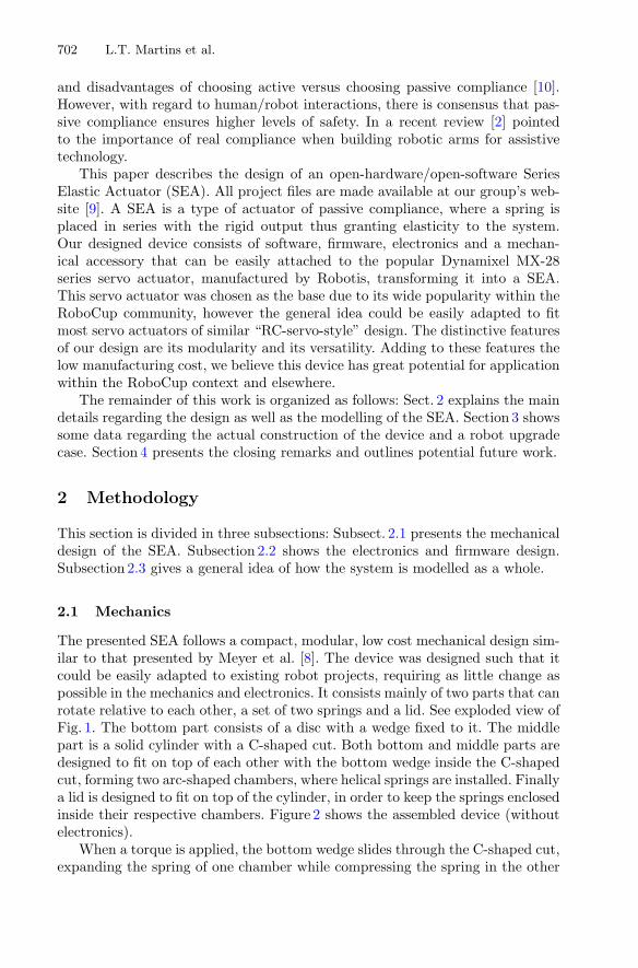
See the block diagram of Fig. 5 for a more complete overview of the model.The dotted box at the top represents the computer responsible for the mid-levelcontrol of the joints1. In the case of an upgrade we suppose the same originaldevice used for communicating instructions and data with the servo actuatorscan be used. The dotted box below represents the original Dynamixel servoactuator, without any firmware changes.
As usual, the rigid servo actuators are programmed for position control.These try to minimize an error e = β∗ − β, where β∗ and β denote respectivelythe desired and the current angular position. When there is no external load(τ = 0) the SEA assembly rotates as a whole and α = 0. However when thereis some load (τ �= 0) then a corresponding angular displacement of the springα will be read by the controller. The total angle of the joint as a whole can beeasily obtained by summing β + α and the result can be used normally (e.g. tocalculate direct kinematics).
1 Tipically a higher level fully featured computer is used for things like planning, visionand data fusion while another mid-level computer takes care of controlling all thejoints in real time.
Modular Series Elastic Upgrade to a Robotics Actuator 705
1/k Controller
ServoController
Spring Load
Computer
Rigid Servo
e
β α
−−
+α∗
+
β∗
−τ
τ∗
RS485
Fig. 5. Block diagram of the SEA system
With Eq. (1), the angular displacement of the spring α is used by the con-troller to calculate the torque τ being applied by the load into the actuator. Atthis point, depending on the final application, either or both τ and β +α can beused combined with other tools such as robot’s inverse kinematics, Jacobian anddynamic models in order to decide a desired torque τ∗ to be applied to the joint.Given this desired torque τ∗, Eq. (1) can be used again, this time to calculate adesired spring displacement α∗, and consequently the desired angular positionto be sent to the servo actuator is calculated as β∗ = α∗ − α − β.
3 Results
The parts were machined in aluminium using CNC code generated from the CADdrawings. To measure the stiffness of the assembled SEA we attached a lever toone of its sides while the other side was fixed to a bench using a vise. Then thelever was placed in the horizontal position and known weights were hung to it,while the resulting angular displacement was measured. To calculate the appliedmoment we used the projected length of the lever on the horizontal plane andthe applied weight combined with the weight of the lever itself. Figure 6 showsthe laboratory test results. Notice that larger displacements move the springoutside its range of linear behaviour. Considering only the linear range, the springstiffness constant was estimated to be approximately k = 0.02 deg/Nm. Giventhat the original actuators are rated at 2.35 Nm, the resulting torque range ofup to 0.7 Nm found in this prototype is restrictive for many applications, howeverthis can be easily adjusted by choosing a different set of springs.
In order to confirm our SEA’s potential for upgrading existing designs weadapted the device to the knees of an existing humanoid robot designed for the

706 L.T. Martins et al.
0.1
0.2
0.3
0.4
0.5
0.6
0.7
0.8
0.9
1
1.1
10 15 20 25 30 35 40 45
τ(N
m)
α (deg)
τ(x) = 0.02α
Fig. 6. Stiffness test
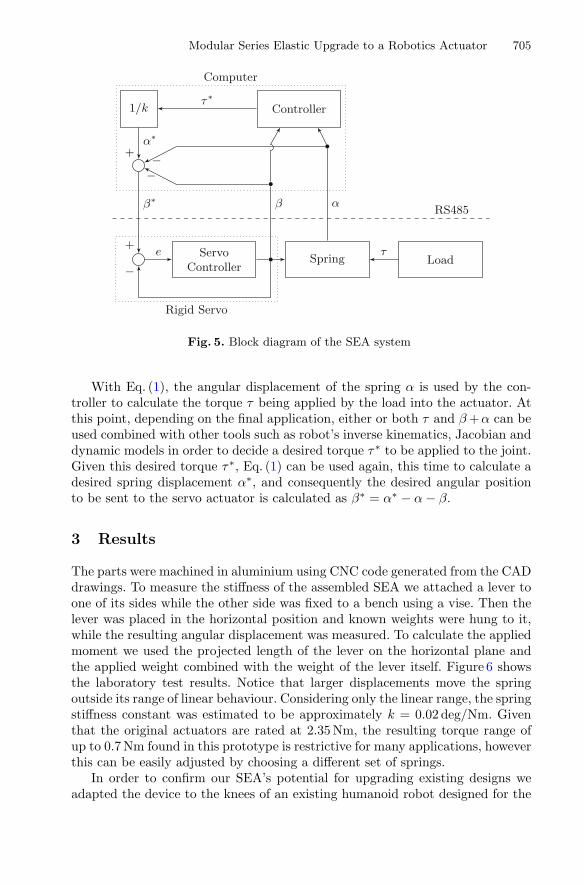
RoboCup Humanoid KidSize Soccer Tournament [1]. This robot is based on theDARwIn-OP platform [4]. All we needed to do was to partially change the designof a single part to accommodate the larger joint width so that the spring couldbe attached to the existing servo actuator. Figures 7 and 8 show respectively theexploded CAD view and the picture of the upgrade.
4 Discussion and Future Work
This paper presented the implementation of a modular and low cost SEA to beused for adding compliance and torque control to existing rigid robot designs.This is the first version of an open software and open hardware system which wehope can be copied and improved upon by other roboticists. We are currentlyfocusing on improving the quality of the design and working on the dynamicalmodel. We have also started testing the design using an alternative rubber-likematerial instead of helicoidal springs.
Upon completion of field tests with current setup with small servos androbots, the authors plan to apply the findings to larger robots with stronger servodrives. We consider compliance of the joints an increasingly crucial property forthe robustness of larger robots, especially with larger weights and falling heights.
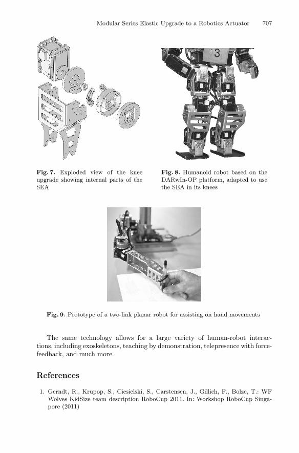
On another case study, we have recently started working on a two-link planarrobot inspired on the robot-aided neuro-rehabilitation technology developed byKrebs and Volpe [6]. In this device we installed two of our SEAs, one in each jointtransforming it into a compliant position and force controlling system. We usedan ordinary pen as the end-effector. Pen movements are monitored allowing theapplication of corrective forces to user movements. This general framework allowsnot only for game-based neuro-rehabilitation applications but also for computerbased dexterity enhancement, where the inference of user intent can be used toimprove upon his or her actions (Fig. 9).
Modular Series Elastic Upgrade to a Robotics Actuator 707
Fig. 7. Exploded view of the kneeupgrade showing internal parts of theSEA
Fig. 8. Humanoid robot based on theDARwIn-OP platform, adapted to usethe SEA in its knees
Fig. 9. Prototype of a two-link planar robot for assisting on hand movements
The same technology allows for a large variety of human-robot interac-tions, including exoskeletons, teaching by demonstration, telepresence with force-feedback, and much more.
References
1. Gerndt, R., Krupop, S., Ciesielski, S., Carstensen, J., Gillich, F., Bolze, T.: WFWolves KidSize team description RoboCup 2011. In: Workshop RoboCup Singa-pore (2011)

708 L.T. Martins et al.
2. Groothuis, S.S., Stramigioli, S., Carloni, R.: Lending a helping hand: toward novelassistive robotic arms. IEEE Robot. Autom. Mag. 20(1), 20–29 (2013)
3. Guizzo, E., Ackerman, E.: The rise of the robot worker. IEEE Spectr. 49(10),34–41 (2012)
4. Ha, I., Tamura, Y., Asama, H., Han, J., Hong, D.: Development of open humanoidplatform DARwIn-OP. In: 2011 Proceedings of SICE Annual Conference (SICE),pp. 2178–2181, September 2011
5. Jain, A., Kemp, C.C.: Pulling open doors and drawers: Coordinating an omni-directional base and a compliant arm with equilibrium point control. In: IEEEInternational Conference on Robotics and Automation (ICRA), pp. 1807–1814(2010)
6. Krebs, H.I., Volpe, B.T.: Rehabilitation robotics. Handb. Clin. Neurol. 110(283–294) (2013)
7. Kushner, D.: The making of arduino. IEEE Spectrum 26 (2011)8. Meyer, F., Sprowitz, A., Lungarella, M., Berthouze, L.: Simple and low-cost com-
pliant leg-foot system. In: 2004 IEEE/RSJ International Conference on IntelligentRobots and Systems (IROS 2004), vol. 1, pp. 515–520, September 2004
9. UFSM: Website of the Grupo de Automacao e Robotica Aplicada (GARRA)(2014). http://garra.ufsm.br/
10. Wang, W., Loh, R.N.K., Gu, E.Y.: Passive compliance versus active compliance inrobot-based automated assembly systems. Ind. Robot 25(1), 48–57 (1998)


![Link IEEE TRANSACTIONS ON ROBOTICS 1 Elastic Structure Preserving (ESP) Control … · 2019. 6. 17. · [10] provides a comprehensive stability analysis for constant. IEEE TRANSACTIONS](https://img.dokumen.tips/doc/110x75/60dd9fdf8a54513bef31bb17/link-ieee-transactions-on-robotics-1-elastic-structure-preserving-esp-control.jpg)