Embed Size (px)
Citation preview

Design of a Highly Biomimetic Anthropomorphic Robotic Hand
towards Artificial Limb Regeneration
Zhe Xu and Emanuel Todorov
Abstract— A wide range of research areas, from telemanip-ulation in robotics to limb regeneration in tissue engineering,could benefit from an anthropomorphic robotic hand that mim-ics the salient features of the human hand. The challenges ofdesigning such a robotic hand are mainly resulted from our lim-ited understanding of the human hand from engineering pointof view and our ability to replicate the important biomechanicalfeatures with conventional mechanical design. We believe thatthe biomechanics of human hand is an essential component ofthe hand dexterity and can be replicated with highly biomimeticdesign. To this end, we reinterpret the important biomechanicaladvantages of the human hand from roboticist’s perspectiveand design a biomimetic robotic hand that closely mimicsits human counterpart with artificial joint capsules, crochetedligaments and tendons, laser-cut extensor hood, and elasticpulley mechanisms. We experimentally identify the workspacesof the fingertips and successfully demonstrate that our proof-of-concept design can be teleoperated to grasp and manipulatedaily objects with a variety of natural hand postures based onhand taxonomy.
I. INTRODUCTION
The significance of designing anthropomorphic robotic
hands most likely originates from the expectation of using
motorized prosthetic hand to restore lost hand dexterity.
Although there is still no consensus about the definition
of human hand dexterity, the biological variations found
in length of bones, branching of tendons, and insertion of
muscles [1] all suggest that dexterity is a highly personal
property that is not only shaped by individual’s motor control
ability, but also inherently bonded to the unique biomechan-
ical characteristics of its very owner, and therefore can not
be generalized without considering the biological difference.
The conventional approach to designing anthropomorphic
robotic hands often involves mechanizing biological parts
with hinges, linkages, and gimbals in order to simplify the
seemingly complicated human counterparts. This approach is
helpful for understanding and approximating the kinematics
of the human hand in general, but inevitably introduces
undesirable discrepancies between the human and robotic
hands. The unique biomechanics of any abled human be-
ing, which includes complicated shapes of bones, varied
rotational axes, and other biomechanical advantages, can be
seen as a validated physical system as a whole. But most
of these salient features are discarded in the mechanizing
process. Although significant amount of efforts have been
made by researchers to solve this mismatch from the control
Authors are with the Department of Computer Science & Engineering,University of Washington, WA 98195, USA
e-mail: [email protected], [email protected]
Fig. 1. The fully assembled biomimetic robotic hand. Left: The palmaraspect of the biomimetic robotic hand system. Top right: The dorsal viewof the robotic hand. Bottom right: The laser-cut extensor hood integratedwith intrinsic muscles. Note: The total weight of our biomimetic robotichand is less than 1 kg (942 grams) including the actuation system.
and sensing aspects, very few work has been done to reduce
the gap from the biomechanical point of view.
The general approach of our proposed method is first
to identify the important biomechanical information of the
human hand and then biomimetically replicate it. This allows
a close replica that shares the same kinematic and even
dynamic properties of its human counterpart. Our design ben-
efits from several important rapid prototyping technologies:
the shape of bones could be first captured with laser/MRI
scanner and then 3D-printed with detailed surface features
such as joint shapes and tendon insertion sites; soft tissues
can be mimicked by using compliant silicone rubbers whose
mechanical properties match that of the skin.
As shown in Fig.1, our approach resulted in a highly
biomimetic anthropomorphic design, which will have poten-
tial impact on studies in both robotics and biology fields.
Besides the obvious application in telemanipulation in which
human operator can directly transfer his/her own dexterity
to the robotic hand, it could also help medical and bi-
ology research in terms of physically preserving personal
biomechanical data and serving as the 3D scaffolds for limb
regeneration research.
In the following sections, we first review related work and
introduce our design motivation. And then we reinterpret
the important biomechanics of the human hand from engi-
neering point of view. Meanwhile, we detail the biomimetic
design and prototyping process of our anthropomorphic
robotic hand. After this, we experimentally investigate the
workspaces of each finger and the thumb. At the end, we

experimentally demonstrate the efficacy of our proof-of-
concept design through grasping and manipulation experi-
ments.
II. RELATED WORK AND MOTIVATION
In order to properly position our proposed biomimetic
robotic hand design, in this section we first briefly review
the most relevant past work in robotics, and then explain the
potential application of the highly biomimetic robotic hands
in medical and biology research, to which end we formed
our design concept.
A. Anthropomorphic robotic/prosthetic hands
Many advanced anthropomorphic robotic hands have been
developed during the past decade. As thoroughly summarized
in a recent review [2], each of them possesses distinctive
features in terms of actuation speed, magnified fingertip
forces, or high degrees of freedom (DOFs), etc. However
they all share the same design concept of mechanizing the
biological counterparts. Their design ideas can be traced
back to the technologies developed for industrial assembly
robots. Equipped with joint and tactile sensors, the motion
of such a human-like robotic hand can be seen as the
coordination of five miniaturized high-precision industrial
robots packed within a palm-sized space. The development
of the anatomically corrected testbed (ACT) hand [3] was the
first try towards replicating the human hand on anatomical
level. However its internal mechanisms are still based on
hinges and gimbals, we therefore categorize it as a spe-
cial type of anthropomorphic robotic hand. The inherent
mismatch between mechanisms of these robotic hands and
biomechanics of human hands essentially prevents us from
using natural hand motion to directly control them. Thus
none of them can achieve the human-level dexterity yet.
The development of prosthetic hands heavily relies on the
lessons we learned from building anthropomorphic robotic
hands. State-of-the-art prosthetic hands can now be con-
trolled with two different methods: Using non-intrusive
methods such as electromyography (EMG) signals collected
from the residual limb or targeted muscle reinnervation re-
gions [4]; or using intrusive methods like directly implanting
microelectrodes at the motor cortex of the brain [5] or cuffing
peripheral nerves with miniaturized electrodes to collect
control inputs [6]. The control of prosthetic hands essentially
relies on human brain. Therefore the same neuroprosthetic
technologies could be more effective if the design of the
prosthesis could be more similar to its biological counterpart.
In contrast to these previous designs, we propose to use a
highly biomimetic design to preserve the salient features of
the human hand. Our design aims to minimize the design
mismatch between robot and human hands for a more
efficient control and a wider application.
B. Design tools for medicine & biology research
We envision our biomimetic hand to become a useful tool
in medicine and biology research. Transplanted hand is the
only existing biological alternative for a lost human hand to
date. Yet the long-waiting list and the slim chance of finding
the right donor keep preventing the method to be regularly
practiced at hospitals. And there are still on-going debates
about the lifelong rejection side-effects. In recent years,
biologists start to investigate the possibility of regrowing
tissues and organs through biofabrication: biocompatible
materials can now be printed to form bone structures [7],
biodegradable artificial ligaments have been used to replace
the torn anterior cruciate ligaments [8], human muscles
have been successfully cultivated inside petri dish [9], and
peripheral nerves can also be regenerated given the right
conditions [10]. All of the these promising technologies
require suitable scaffolds for the growth of grafted cells.
When it comes to regrowing centimeter scale limbs, such
as the rat forelimb, decellularised cadaver parts are required
as scaffolds [11]. However even if the same techniques can
be scaled up for human trails, the limitation of donors could
eventually become a bottleneck. Besides, in medical research
most of the in-vivo studies conducted on cadaver hands face
constantly changing conditions since the decay process of
the organic tissues is irreversible. The problem of biological
variations caused by individual differences could also result
in a long lasting debate. These limitations and drawbacks
motivate us to seek for an alternative form of scaffold
that can reliably preserve the biomechanical information of
human hand in a physical working model.
An biomimetic anthropomorphic robotic hand that mimics
the biomechanics of the human hand can be first vali-
dated in robotics lab and then mass-produced with bio-
compatible materials to meet the requirement of different
medical/biological applications. While it is often regarded
unnecessary to directly copy the bio-blueprint of the bi-
ological counter parts, it is possible to replicate critical
biomechanical features of the human hand step by step.
The key of success lies in a thorough understanding of the
biomechanics of the human hand from the engineering point
of view and the ability to materialize the findings.
III. DEVELOPMENT OF THE HIGHLY BIOMIMETIC
ROBOTIC HAND
In this section, we identify the important biomechanical
features that shape the movement of human hand from
the following aspects: the bones, joints, ligaments, tendons,
extensor hood, and tendon sheaths. Instead of examining the
human hand directly from a hand surgeon’s perspective, in
each of the following subsection we explain the essential
hand biomechanics in engineering language and then discuss
the ways to replicate these features with our biomimetic
design.
A. The bones and joints
As shown in Fig. 2, the human hand has four fingers
and one thumb and is composed of 27 bones containing 8
tightly packed small wrist bones1. Each finger consists of
1We are interested in understanding the joint mechanism that enablesfinger movement, so the wrist bones (except for the trapezium bone) arenot in scope of our investigation at this stage.

Fig. 2. The definition of the bones and joints of the human left hand(modified from [12]). Note: The trapezium bone is shown in red.
three phalanges and one metacarpal bones. The thumb is an
exception, it only has two phalanges besides the metacarpal
bone. But the opposable thumb accounts for a big portion
of the entire hand function. The trapezium bone located at
the base of the thumb has been found to be the critical
component that enables the thumb opposition (labeled in red
in Fig. 2). Together with the thumb’s metacarpal bone, they
form the carpometacarpal (CMC) joint of the thumb.
A joint is the connection between two adjacent bones
whose shared contacting surfaces determine the possible
motions of the joint. Different types of joints facilitate a
different set of finger motions, known as the range of motion
(ROM). The metacarpophalangeal (MCP) joints are formed
by the connection of phalanges to the metacarpals. Depend-
ing on the distance to the MCP joint, there exist two more
types of joints, namely, the proximal interphalangeal(PIP)
joint and distal interphalangeal(DIP) joint. Based on this
definition, the thumb only has one DIP joint between the
two thumb phalanges. During the bending motion, the three
finger joints work as mechanical hinges. However, the MCP
joints have one extra set of active ROM that allows the finger
to move from side to side, which are known as the abduction
and adduction (ad/b) motions. In addition, the MCP joints
also have one passive ROM that permits twisting motion
around the axis of the finger phalanges. Thus, in the case
of four fingers, we are only going to focus on describing
the mechanism of the MCP joint, since the 1-DOF PIP and
DIP joints can be seen as a simplified case. Different from
the fingers, the complicated thumb movements are resulted
from the contact between the trapezium and first metacarpal
bones at the CMC joint. Due to the irregular shape of the
trapezium bone (see Fig. 3), the exact locations of its joint
axes are still under debate, but the CMC joint has been
commonly explained as a saddle joint that allows the thumb
to have a wide ROM - up (adduction) and down(abduction),
bent(flexion) and straightened (extension), and the ability to
move across the palm (opposition).
When designing robotic hands, robotics researchers often
Fig. 3. Complicated bone shapes at the CMC joint of the thumb. Left: Thecommon mechanical analogy of the first metacarpal and trapezium bones(shown in red, modified from [12]). Right: The fixed joint axes used forexplaining different thumb movements.
choose 2-DOF universal joints for the MCP joints. The
universal joint is good at transmitting rotary motion in shafts,
but lacks the 1-DOF that allows the finger to passively twist
with respect to the axial direction at the MCP joint. The
same problem worsens when it comes to designing the CMC
joint. Because the CMC joint requires not only saddle-shaped
surfaces but also curved rotation axis that support rotation,
sliding, translation, and pivoting motions [13]. Thus, none of
the existing anthropomorphic robotic hands can restore the
natural thumb motions with conventional mechanical joints
that use fixed rotation axes. In addition, the irregular shapes
of articular surfaces are also responsible for distributing
stress. It is estimated that a tip pinch of 1 kg will generate
12 kg of joint compression at the CMC joint. For a power
grip, the load could become as high as 120 kg [14].
In order to maximally preserve the important surface
features of bones and joints, we 3D print artificial bones from
the laser-scanned model of a cadaver skeleton hand [15]. As
shown in Fig. 1, all finger segments of our robotic hand
(excluding the actuator brackets) can be printed out on a 20
× 20 cm tray (Dimension BST 768, Stratasys). Depending
on the setting of the inner structure and resolution of the
parts (0.025 mm), the total printing time could be less than
20 hours.
B. The joint ligaments
The ROM at each finger joint is restricted by the length
of ligaments. As shown in Fig. 4, ligaments are tough
bands of fibrous tissues inserted on both sides of the two
adjacent bones. Two important branches are called collateral
ligaments. Similar structures can be found in all the finger
joints with variations in length and thickness. Their function
is to stabilize the joint, shape the ROM, and prevent abnormal
sideways bending of each joint. For example, at the MCP
joint, the collateral ligaments originate from the dorsal side
of the metacarpal bone and end near the palmar side of the
adjacent finger phalanx. In this way, the collateral ligaments
get taut when the finger bends, and become relaxed once the
finger straightens. This is why our index finger can easily
move from side to side when it extends, but has very limited
side motions once it fully bends. The thick ligament formed

Fig. 4. Schematic showing the function of collateral ligaments and volarplate at the MCP joint.P jo
Fig. 5. The skeleton of the 3D-printed finger connected by crochetedligaments and laser-cut joint soft tissues. Note: All the crocheted ligamentsare anchored by 1 mm screws at their biological insertion sites.
on the palmar side of the finger is called volar plate. Like
the collateral ligaments, the volar plate also has insertions
on both sides of the bones. Its function is to prevent the
occurrence of the finger deformity from hyper-extension.
Together with other accessory ligaments and soft tissues,
collateral ligaments and volar plate form important structure
known as the joint capsule.
Our artificial joint capsule design allows each robotic
finger to be quickly assembled as shown in Fig. 5. One pair
of the crocheted ligaments is used to mimic the two collateral
ligaments located on the sides of each finger joint. Similarly,
the function of the volar plate is replaced by two crocheted
ligaments anchored across each joint. Laser-cut rubber sheet
is used to mimic the soft tissues providing the human-like
compliance. Based on the ROM of each joint, the dimension
of these components varies in size and length. Compared to
our previously proposed joint design [16], our current design
greatly reduced the fabrication time.
C. Tendons and muscles
Between the bones and muscles, there are two groups
of tendons in the human hand. The ones straightening the
fingers are called extensor tendons, the ones bending the
fingers are called flexor tendons. The excursion motions of
the tendons originate from the corresponding muscle groups
located in the forearm. If we treat the muscles as the actuators
that output contraction forces, the tendons of the hand serve
as the transmission system that smartly partition the forces
and smoothly deliver torques to each finger joint. As shown
in Fig. 6(a), starting from the wrist, the extensor tendons
branch out and have multiple insertion sites on the dorsal
side of the finger bones. On the palmar side, after passing
through the carpal tunnel, the flexor tendons (see Fig. 6(d))
travel through a series of pulley-like tendon sheaths grown
onto the palmar side of the bones and eventually insert at the
base of the DIP and PIP joints. The collaborative motions of
the two tendon groups make fluent hand movement possible.
The large muscle groups that directly connect to the central
branch of the flexor and extensor tendons are called extrinsic
muscles. Most of them originate from the elbow and have
muscle bellies located in the the forearm. However there also
exist several small muscle groups called intrinsic muscles
that are often slim enough to reside in the gap between
the two adjacent metacarpal bones. The majority of these
small muscles start from the wrist of hand and connect to
the thin branches (the extensor hood) of the extensor tendons
of each finger near the MCP joint. One important function of
these intrinsic muscles is to provide passive reflex-mediated
stiffness at finger joints during various hand activities. We
use resilient, laser-cut rubber sheet to mimic these small
muscles as a joint stabilization mechanism (see Fig. 1).
In total, ten Dynamixel servos (nine MX-12W and one
AX-12A) are used to mimic the important large muscles
and actuate our proposed robotic hand (as shown in Fig. 1).
Two servos are used to control the flexion and extension
of the ring and little fingers through a differential pulley
transmission (see Fig. 8). The index and middle fingers are
separately controlled by two pairs of servos so that each of
them can bend and straighten independently. In addition, they
also share an extra servo for a coupled control at their MCP
joints2. We use three actuators to control the thumb. One of
them is an AX-12A Dynamixel servo that has a larger gear
ratio (254/1) than others (32/1) and is used for the extension
and abduction of the thumb. The other two servos of thumb
are assigned to control the flexion and adduction motions,
respectively. The palm has one underacutated DOF that relies
on the flexion motion of the ring and little fingers. Although
the wrist of the current version only serves as a static base for
testing the fingers, its cable routing structure closely mimics
the capral tunnel of the human hand.
D. Extensor hood
Most of our daily tasks involving hand motions require
the contraction of strong muscles connecting to the flexor
tendons. Therefore during grasping, the extensor tendons
mainly work as a breaking system that constantly regulates
the torques at finger joints. The functionality of the breaking
system relies on a fibrous structure known as the extensor
hood. The extensor hood is a thin, complex, and collagen-
based web structure that directly wraps around the finger
2In our current design, the abduction/adduction motion is passivelyregulated by the laser-cut intrinsic muscles integrated at the MCP jointsfor all the fingers

Fig. 6. The important biomechanical advantages of the extensor and flexor tendons of a human left hand.(a) Schematic drawing of the extensor tendons.(b) A simplified geometric representation of the extensor hood. (c) The regulation of torques at the PIP joint during finger flexion. (d) Schematic drawing ofthe flexor tendons. (e)The bulging process of the tendon sheaths (the pulleys) during finger flexion. (f) Mechanical analogy of the bending finger showingthe increase in moment arms under the effects of elastic pulleys.
phalanges from the dorsal side. Its structure can be geomet-
rically represented by a two-layer web as shown in Fig. 6(b).
The first layer of the extensor hood is called lateral bands.
It has an insertion site at the base of the DIP joint, and
split into two small ligaments across the PIP joint. This
splitting mechanism smartly regulates the breaking torques at
the PIP joint based on different postures of the finger during
its bending process (see Fig. 6(c)). As shown in the lateral
view, when the finger straightens, the two small ligaments are
above the rotation axis at the PIP joint serving as branches of
the extensor tendons. When the flexor tendons keep pulling
and extensor tendons getting stretched, the finger starts
its bending process during which the two small ligaments
continue to glide off from the PIP joint and eventually
pass downwards the rotation axis. Hereinafter, although the
extensor tendons are still transmitting forces into the two
small branches via the web structure, the two small branches
are no longer behaving like extensor tendons at the PIP joint,
but instead they begin to help flex the finger by providing
increasing flexion torques at the PIP joint. When the finger
straightens, the above process repeats in the reverse order.
The second layer of the extensor hood is known as the
central slip with a insertion point at the base of the PIP
joint. Its function is to help extend/flex the PIP joint. One
of its tendon branches is often connected to a small intrinsic
muscle, namely, the lumbrical muscle. It has been reported
that the lumbricals work as flexor tendons at the MCP joints,
but can help extend the PIP and DIP joints via the extensor
hood mechanism. Due to its variations in size and inserting
locations, the function of the lumbricals are not unanimously
agreed yet. So we treat them as a part of the intrinsic muscles
without emphasizing its uniqueness in Fig. Fig. 6(c). In sum,
the complex, web structure of the extensor hood smartly
transmits muscle forces to finger joints through the gliding
mechanism.
As shown in Fig. 1, highly resilient rubber sheets are
first laser cut into the shape of extensor hood (with intrinsic
muscles integrated) and then attached to the skeleton of the
fingers (see Fig. 7) at biological insertion sites to mimic
the passive behavior of the extensor hood, leaving servos to
achieve the active extension of the finger through the gliding
mechanisms. This is an important biomechanical advantage
that we incorporated into our robotic hand design.
E. Tendon sheaths
As shown in Fig. 6(e), the tendon sheaths are fibrous
tissues that wrap around the flexor tendons and have multiple
insertions on the dorsal side of finger bones. Due to their
important functions, each section of the tendon sheaths has
been named after a numbered annular pulley in nomencla-
tures of hand anatomy based on their distances to the MCP
joint. Mechanical engineers design different pulley systems
to apply forces and transmit power through cables. The
tendon sheaths in the human hand work as a series of elastic
pulleys to help efficiently transmit flexion forces from the
muscles to the joints. Since the tendon sheaths can flatten
down when the finger straightens and bulge out when the
finger bends [17].
As illustrated in Fig. 6(e) and (f), if the flexor tendon starts
pulling a straightened finger with constant force and speed,
the initial moment arms at joints are small and therefore
can cause a fast bending motion of the finger but result
in small flexion torques at the joints. However when the
finger starts bending, the bulging effect of tendon sheaths
greatly increases the moment arms at joints leading to a
slowed finger motion with rapidly magnified flexion torques.
With the elastic pulley system, the human hand can keep
the torques at the finger joints small when approaching
the object, but quickly deliver large torques to the finger
joints when forming a grip. Combined with the gliding
mechanisms, this is another biomechanical advantage that
helps the flexor tendons to dominate the finger dynamics
during flexion motions.
As shown in Fig. 7, three patches of laser-cut rubber
sheets are used to mimic the elastic pulley mechanism.
The flexor tendon made of high strength Spectra R© strings
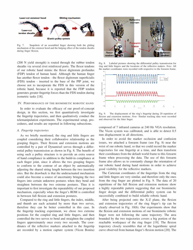
Fig. 7. Snapshots of an assembled finger showing both the glidingmechanism of the extensor hood and the bulging effect of the tendon sheathsduring finger flexion.
(200 N yield strength) is routed through the rubber tendon
sheaths via several rivet reinforced ports. The flexor tendons
of our robotic hand mimic the flexor digitorum profundus
(FDP) tendon of human hand. Although the human finger
has another flexor tendon - the flexor digitorum superficialis
(FDS) tendon - inserted to the base of the PIP joint, we
choose not to incorporate the FDS in this version of the
robotic hand, because it is reported that the FDP tendon
generates greater fingertip forces than the FDS tendon during
isometric tasks [18].
IV. PERFORMANCE OF THE BIOMIMETIC ROBOTIC HAND
In order to evaluate the efficacy of our proof-of-concept
design, in this section, we first quantitatively investigate
the fingertip trajectories, and then qualitatively conduct the
telemanipulation experiments. The experimental setup, pro-
cedures, and results are reported in following subsections.
A. Fingertip trajectories
As we briefly mentioned, the ring and little fingers are
coupled considering their collaborative relationship as the
grasping fingers. Their flexion and extension motions are
controlled by a pair of Dynamixel servos through a differ-
ential pulley transmission as shown in Fig. 8. The benefit of
using such a pulley structure is to provide an extra source
of hand compliance in addition to the build-in compliance at
each finger joint, since it allows the two grasping fingers
to conform to the contour of an object by automatically
adjusting the shared string length between the two insertion
sites. But the drawback is that the underactuated mechanism
could also become a source of uncertainty bringing the two
fingers into certain unknown postures when they bend and
straighten between the two extreme postures. Thus it is
important to first investigate the repeatability of our proposed
mechanism, especially when the finger’s ROM is controlled
in between full flexion and extension postures.
Compared to the ring and little fingers, the index, middle,
and thumb are each actuated by more than two servos,
therefore they can be better controlled in this case. In
the fingertip tracking experiment, we chose two extreme
positions for the coupled ring and little fingers, and then
controlled the two servos to bend and straighten the coupled
fingers approximately once every two seconds. The coor-
dinates of the reflective markers attached to the fingertip
are recorded by a motion capture system (Vicon Bonita)
Fig. 8. Labeled pictures showing the differential pulley transmission forring and little fingers and the locations of the reflective makers. Note: Allthe marker coordinates were recorded with respective to the forearm frame.pec
Fig. 9. The displacement of the ring’s fingertip during 20 repetition offlexion and extension motions. Note: Similar tracking data were recordedand observed for the litter finger.
composed of 7 infrared cameras at 240 Hz VGA resolution.
The Vicon system was calibrated, and is able to detect 0.5
mm displacement in all directions.
In order to avoid the marker occlusion and confusion
issues, we attached a forearm frame (see Fig. 8) near the
wrist of our robotic hand, so that we could record the marker
trajectories for one fingertip at a time, and then transform
their coordinates from the default world frame to this forearm
frame when processing the data. The use of this forearm
frame also allows us to constantly change the orientation of
our robotic hand during hand motions in order to achieve
good visibility for the reflective markers.
The Cartesian coordinates of the fingertips from the ring
and little fingers are very similar, and therefore only the ones
from the ring finger are plotted in Fig. 9. The data of 20
repetitions of the full flexion and extension motions show
a highly repeatable pattern suggesting that our biomimetic
finger design and the differential pulley system can be
successfully combined to build reliable robotic hand.
After being projected onto the X-Z plane, the flexion
and extension trajectories of the ring finger’s tip can be
clearly observed in Fig. 10(b). Our experiments show that
the flexion and extension motions of our biomimetic robotic
finger were not following the same trajectory. The area
bounded by the two trajectories covers a big portion of the
reachable workspace of the ring finger [19]. The flexion
trajectory closely resembles that of the logarithmic spiral
curve observed from human finger’s flexion motion [20]. The

(a)
(b) (c)
Fig. 10. The trajectories of the fingertips of our biomimetic robotichand. (a) 3D scatter plot of fingertip trajectories. (b) The ring fingertip’strajectories projected onto the X-Z plane. (Note: The scatter plot is from the20 repetitions of the full flexion and extension motions.) (c) The trajectoriesof the fingertips projected onto the X-Z plane.
difference between the flexion and extension fingertip trajec-
tories results from the sequential joint movements shaped by
joint stiffness. As shown in Fig. 7, the variable joint stiffness
is regulated by the gliding mechanism of the extensor hood
and the elastic pulleys of the tendon sheaths.
The fingertip trajectories of other digits were also
recorded. Unlike the pre-determined inputs for the ring and
little fingers, the repetitive movements of the index, middle,
and thumb were teleoperated by the human operator through
our custom-made data glove3. As shown in Fig. 10, the
two principal components of the thumb motions, namely
the flexion/extension and the abduction/adduction were tested
separately. The teleoperation results in more scattered data
points compared to the ones collected from the prepro-
grammed motions of ring and little fingers (see Fig. 9).
B. Object grasping and manipulation
In order to further evaluate the overall performance of
our robotic hand, we conducted grasping and manipulation
experiments using 31 objects from the prioritized list [21].
During the test a human operator hands different objects to
the robotic hand with his right hand, meanwhile, used his
left hand to teleoperate the digits of the robotic hand to
grasp/manipulate the object via the data glove (see Fig. 11).
This process is known as the tele-manipulation during which
3Details about the data glove can be found in [15], but is out of the scopeof this paper.
Fig. 11. Snapshots showing the teleoperation process of our biomimeticrobotic hand.
Fig. 12. The hand taxonomy realized by our biomimetic robotic hand(Note: see the taxonomy figure in [22] for comparison).
the movement of the robotic hand is both controlled and
guided by the same human operator’s hand motion and
visual feedback. This experiment can be seen as a series of
cooperative grasping tasks between the human operator and
the robotic hand in which the former could clearly monitor
the status of the grasped object without the occlusion issue
at the grasping site (see our video submission for details).
During the object grasping task, we observed that different
grasping postures can be naturally transferred from the
human operator to our biomimetic robotic hand, particu-
larly from the motion of the thumb. This is because our
biomimetic robotic hand successfully preserves the important
biomechanics of the human hand that essentially determines
the hand kinematics. The resulting grasps cover most of the
grasping types defined by human hand taxonomy [22], except
for the ones that require independent control of the ring and
little fingers (see Fig. 12).
Last but not least, we tested the in-hand manipulation
ability of our biomimetic robotic hand. As shown in Fig. 13,
the whiteboard eraser was successfully regrasped from hori-
zontal to vertical position through a series of continuous hand
motions involving the use of all the digits. It is interesting
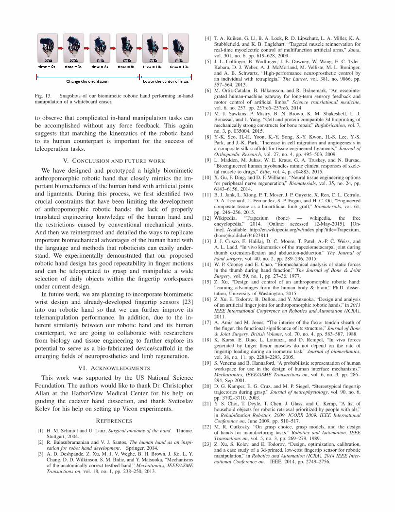
Fig. 13. Snapshots of our biomimetic robotic hand performing in-handmanipulation of a whiteboard eraser.
to observe that complicated in-hand manipulation tasks can
be accomplished without any force feedback. This again
suggests that matching the kinematics of the robotic hand
to its human counterpart is important for the success of
teleoperation tasks.
V. CONCLUSION AND FUTURE WORK
We have designed and prototyped a highly biomimetic
anthropomorphic robotic hand that closely mimics the im-
portant biomechanics of the human hand with artificial joints
and ligaments. During this process, we first identified two
crucial constraints that have been limiting the development
of anthropomorphic robotic hands: the lack of properly
translated engineering knowledge of the human hand and
the restrictions caused by conventional mechanical joints.
And then we reinterpreted and detailed the ways to replicate
important biomechanical advantages of the human hand with
the language and methods that roboticists can easily under-
stand. We experimentally demonstrated that our proposed
robotic hand design has good repeatability in finger motions
and can be teleoperated to grasp and manipulate a wide
selection of daily objects within the fingertip workspaces
under current design.
In future work, we are planning to incorporate biomimetic
wrist design and already-developed fingertip sensors [23]
into our robotic hand so that we can further improve its
telemanipulation performance. In addition, due to the in-
herent similarity between our robotic hand and its human
counterpart, we are going to collaborate with researchers
from biology and tissue engineering to further explore its
potential to serve as a bio-fabricated device/scaffold in the
emerging fields of neuroprosthetics and limb regeneration.
VI. ACKNOWLEDGMENTS
This work was supported by the US National Science
Foundation. The authors would like to thank Dr. Christopher
Allan at the HarborView Medical Center for his help on
guiding the cadaver hand dissection, and thank Svetoslav
Kolev for his help on setting up Vicon experiments.
REFERENCES
[1] H.-M. Schmidt and U. Lanz, Surgical anatomy of the hand. Thieme.Stuttgart, 2004.
[2] R. Balasubramanian and V. J. Santos, The human hand as an inspi-
ration for robot hand development. Springer, 2014.[3] A. D. Deshpande, Z. Xu, M. J. V. Weghe, B. H. Brown, J. Ko, L. Y.
Chang, D. D. Wilkinson, S. M. Bidic, and Y. Matsuoka, “Mechanismsof the anatomically correct testbed hand,” Mechatronics, IEEE/ASME
Transactions on, vol. 18, no. 1, pp. 238–250, 2013.
[4] T. A. Kuiken, G. Li, B. A. Lock, R. D. Lipschutz, L. A. Miller, K. A.Stubblefield, and K. B. Englehart, “Targeted muscle reinnervation forreal-time myoelectric control of multifunction artificial arms,” Jama,vol. 301, no. 6, pp. 619–628, 2009.
[5] J. L. Collinger, B. Wodlinger, J. E. Downey, W. Wang, E. C. Tyler-Kabara, D. J. Weber, A. J. McMorland, M. Velliste, M. L. Boninger,and A. B. Schwartz, “High-performance neuroprosthetic control byan individual with tetraplegia,” The Lancet, vol. 381, no. 9866, pp.557–564, 2013.
[6] M. Ortiz-Catalan, B. Hakansson, and R. Branemark, “An osseointe-grated human-machine gateway for long-term sensory feedback andmotor control of artificial limbs,” Science translational medicine,vol. 6, no. 257, pp. 257re6–257re6, 2014.
[7] M. J. Sawkins, P. Mistry, B. N. Brown, K. M. Shakesheff, L. J.Bonassar, and J. Yang, “Cell and protein compatible 3d bioprinting ofmechanically strong constructs for bone repair,” Biofabrication, vol. 7,no. 3, p. 035004, 2015.
[8] Y.-K. Seo, H.-H. Yoon, K.-Y. Song, S.-Y. Kwon, H.-S. Lee, Y.-S.Park, and J.-K. Park, “Increase in cell migration and angiogenesis ina composite silk scaffold for tissue-engineered ligaments,” Journal of
Orthopaedic Research, vol. 27, no. 4, pp. 495–503, 2009.[9] L. Madden, M. Juhas, W. E. Kraus, G. A. Truskey, and N. Bursac,
“Bioengineered human myobundles mimic clinical responses of skele-tal muscle to drugs,” Elife, vol. 4, p. e04885, 2015.
[10] X. Gu, F. Ding, and D. F. Williams, “Neural tissue engineering optionsfor peripheral nerve regeneration,” Biomaterials, vol. 35, no. 24, pp.6143–6156, 2014.
[11] B. J. Jank, L. Xiong, P. T. Moser, J. P. Guyette, X. Ren, C. L. Cetrulo,D. A. Leonard, L. Fernandez, S. P. Fagan, and H. C. Ott, “Engineeredcomposite tissue as a bioartificial limb graft,” Biomaterials, vol. 61,pp. 246–256, 2015.
[12] Wikipedia, “Trapezium (bone) — wikipedia, the freeencyclopedia,” 2014, [Online; accessed 12-May-2015]. [On-line]. Available: http://en.wikipedia.org/w/index.php?title=Trapezium(bone)&oldid=634623814
[13] J. J. Crisco, E. Halilaj, D. C. Moore, T. Patel, A.-P. C. Weiss, andA. L. Ladd, “In vivo kinematics of the trapeziometacarpal joint duringthumb extension-flexion and abduction-adduction,” The Journal of
hand surgery, vol. 40, no. 2, pp. 289–296, 2015.[14] W. P. Cooney and E. Chao, “Biomechanical analysis of static forces
in the thumb during hand function,” The Journal of Bone & Joint
Surgery, vol. 59, no. 1, pp. 27–36, 1977.[15] Z. Xu, “Design and control of an anthropomorphic robotic hand:
Learning advantages from the human body & brain,” Ph.D. disser-tation, University of Washington, 2015.
[16] Z. Xu, E. Todorov, B. Dellon, and Y. Matsuoka, “Design and analysisof an artificial finger joint for anthropomorphic robotic hands,” in 2011
IEEE International Conference on Robotics and Automation (ICRA),2011.
[17] A. Amis and M. Jones, “The interior of the flexor tendon sheath ofthe finger. the functional significance of its structure,” Journal of Bone
& Joint Surgery, British Volume, vol. 70, no. 4, pp. 583–587, 1988.[18] K. Kursa, E. Diao, L. Lattanza, and D. Rempel, “In vivo forces
generated by finger flexor muscles do not depend on the rate offingertip loading during an isometric task,” Journal of biomechanics,vol. 38, no. 11, pp. 2288–2293, 2005.
[19] S. Venema and B. Hannaford, “A probabilistic representation of humanworkspace for use in the design of human interface mechanisms,”Mechatronics, IEEE/ASME Transactions on, vol. 6, no. 3, pp. 286–294, Sep 2001.
[20] D. G. Kamper, E. G. Cruz, and M. P. Siegel, “Stereotypical fingertiptrajectories during grasp,” Journal of neurophysiology, vol. 90, no. 6,pp. 3702–3710, 2003.
[21] Y. S. Choi, T. Deyle, T. Chen, J. Glass, and C. Kemp, “A list ofhousehold objects for robotic retrieval prioritized by people with als,”in Rehabilitation Robotics, 2009. ICORR 2009. IEEE International
Conference on, June 2009, pp. 510–517.[22] M. R. Cutkosky, “On grasp choice, grasp models, and the design
of hands for manufacturing tasks,” Robotics and Automation, IEEE
Transactions on, vol. 5, no. 3, pp. 269–279, 1989.[23] Z. Xu, S. Kolev, and E. Todorov, “Design, optimization, calibration,
and a case study of a 3d-printed, low-cost fingertip sensor for roboticmanipulation,” in Robotics and Automation (ICRA), 2014 IEEE Inter-
national Conference on. IEEE, 2014, pp. 2749–2756.