Embed Size (px)
Citation preview
Research ArticleDesign of a 25MWe Solar Thermal Power Plant inIran with Using Parabolic Trough Collectors and a Two-TankMolten Salt Storage System
Aidin Alinezhad Kordmahaleh,1 Mohammad Naghashzadegan,2 Kourosh Javaherdeh,2 andMohammadreza Khoshgoftar2
1Department of Intelligent Hydraulics and Automation, Tampere University of Technology, Tampere, Finland2Department of Mechanical Engineering, Faculty of Engineering, University of Guilan, Rasht, Iran
Correspondence should be addressed to Mohammad Naghashzadegan; [email protected]
Received 4 May 2017; Revised 4 August 2017; Accepted 22 August 2017; Published 22 November 2017
Academic Editor: Philippe Poggi
Copyright © 2017 Aidin Alinezhad Kordmahaleh et al. This is an open access article distributed under the Creative CommonsAttribution License, which permits unrestricted use, distribution, and reproduction in any medium, provided the original workis properly cited.
Nowadays, parabolic trough solar thermal plants are prevalent around the world. In different areas concerning the amount of solarradiation, their standard size is approximately between 20 and 100MWe. Certainly, the right size of the solar field is the firstselection with regard to nominal electrical power. A vast area will be economically unreasonable whereas a small area willmainly cause the power plant to operate at the part-load condition. This paper presents an economic modeling of a solarparabolic trough plant, operating at 25MWe in Yazd, Iran. The varying types of collector dimensions have been investigated;then, by selecting autumnal equinox (22 September) at 12:00 PM as the design point, thermal performance of the solar powerplant has been featured annually, in all conditions. The total operating time of the power plant is about 1726 hours (1248 hoursin full-load condition). In the end, the effect of thermal storage tanks has been analyzed to save extra solar heat and use it atnights in hot months. By implementing a storage system, the total operating time will be increased to 3169 hours (2785 in full-load condition). Moreover, 7974GJ useful thermal energy can be obtained from the solar field and storage system.
1. Introduction
Nowadays, the global warming and green gas effect are themost important hazards for the Earth’s future. It seems thatthe optimum solution is using renewable energy resourcesto stop their adverse influences on human life. The solarresource has been taken into account in several researchesas the most extensive resource since the last decades [1].Parabolic trough technology has demonstrated the truthof being the most fully grown and of having minimumexpense in solar thermal technology [2]. Solar parabolictrough collectors are efficiently employed for high temper-ature (300–400°C) without any serious degradation in effi-ciency. Consequently, most of the construction projects oftrade solar power plants are focused on this kind of collec-tors; some parabolic trough power plants are planned to
be built in USA, Spain, and Middle East [3]. They contain asolar field, a steam generator, a Rankine cycle, and a fossilfuel (backup) system [4].
Although a thermal storage system was not used veryoften in ancient parabolic trough plants (some exceptionssuch as Andasol-1 in Spain) [5], today, the storage systemis considered an essential section because in some regionlike Nevada, only 2% of fossil fuel hybridization is permittedto reduce the transient effects [6]. With no doubt, the nextparabolic trough plants will contain storage systems becausethe schedule of hourly operation can be programmedautomatically [1].
To keep oil temperature higher than the minimum range,fossil fuel hybridization is commonly done by an oil heater.Another system that operates during the night and extendednoninsolation period is a fossil fuel that fired the boiler to
HindawiInternational Journal of PhotoenergyVolume 2017, Article ID 4210184, 11 pageshttps://doi.org/10.1155/2017/4210184
originate steam for turbine seals. In a solar power plant, theusual heat transfer fluid (HTF) is oil that operates as an inter-mediate object between the power cycle and solar field [7].
As it was noted, Middle East is a favorite place from theviewpoint of solar radiation. In this specific area, Iran hassome more favorable characteristics for installing a solarpower plant like having the hot and dry weather for a coupleof months in sunny periods, which results in the high rate ofair cleanliness, especially in the central region. Therefore,Yazd city, which is in the center of Iran and near two wilder-nesses, has been selected [8]. Due to economic issues andproportion of solar radiation in Iran, the nominal electricalpower has been assumed to be 25MWe.
The model, implemented in this article, contains a choiceof the design point of the power plant wherein the powerplant should operate at nominal power just with solar energy.Because the storage system would be included in thisresearch, therefore, the design point should be chosen amongsome days which have moderate solar radiation. It causesextra received thermal energy for storage in sunny periods.Then, the number and length of collectors (trough length)will be optimized, and next, the thermal performance of thesolar field will be analyzed annually. Mass flow, received solarpower, and efficiency of collectors are the three key featuresof a solar field that will be calculated in several sunny months.At the end, a heat storage system (two tanks of molten salt)has been taken into account to improve the operating hoursof the power plant.
2. Identifying Solar Field Parameters at theDesign Point
2.1. Power Steam Cycle (Rankine). As it was mentioned,the power plant operates at 25MWe. Experimentally, four
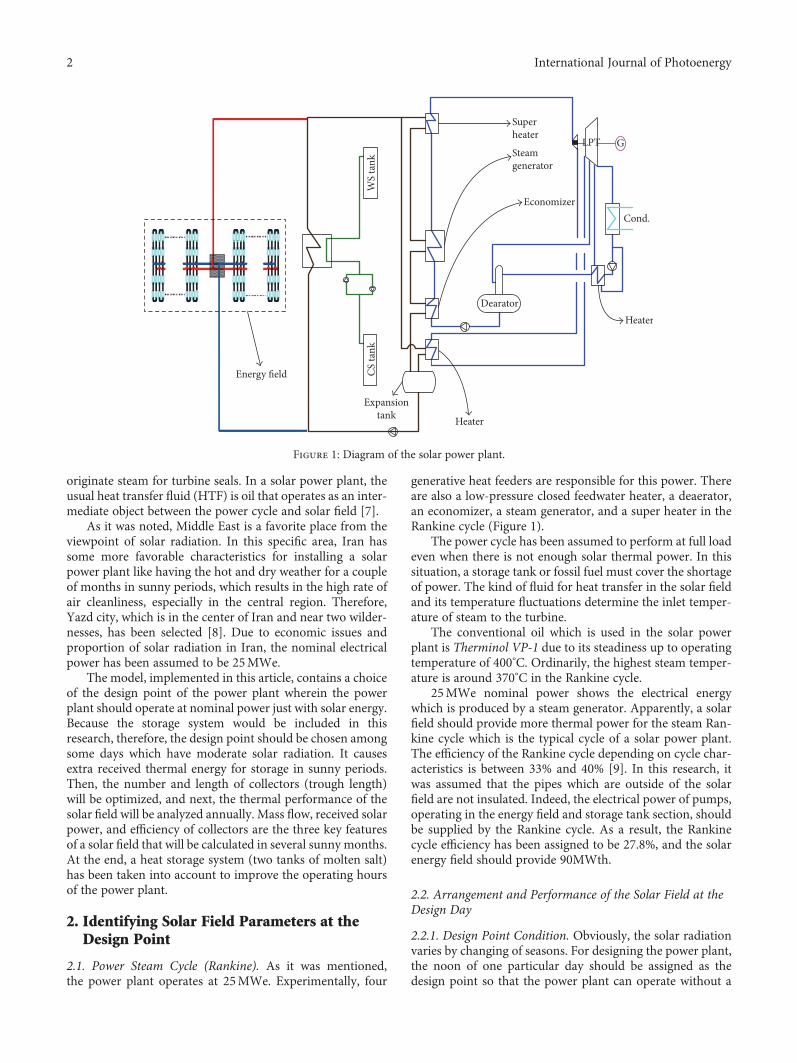
generative heat feeders are responsible for this power. Thereare also a low-pressure closed feedwater heater, a deaerator,an economizer, a steam generator, and a super heater in theRankine cycle (Figure 1).
The power cycle has been assumed to perform at full loadeven when there is not enough solar thermal power. In thissituation, a storage tank or fossil fuel must cover the shortageof power. The kind of fluid for heat transfer in the solar fieldand its temperature fluctuations determine the inlet temper-ature of steam to the turbine.
The conventional oil which is used in the solar powerplant is Therminol VP-1 due to its steadiness up to operatingtemperature of 400°C. Ordinarily, the highest steam temper-ature is around 370°C in the Rankine cycle.
25MWe nominal power shows the electrical energywhich is produced by a steam generator. Apparently, a solarfield should provide more thermal power for the steam Ran-kine cycle which is the typical cycle of a solar power plant.The efficiency of the Rankine cycle depending on cycle char-acteristics is between 33% and 40% [9]. In this research, itwas assumed that the pipes which are outside of the solarfield are not insulated. Indeed, the electrical power of pumps,operating in the energy field and storage tank section, shouldbe supplied by the Rankine cycle. As a result, the Rankinecycle efficiency has been assigned to be 27.8%, and the solarenergy field should provide 90MWth.
2.2. Arrangement and Performance of the Solar Field at theDesign Day
2.2.1. Design Point Condition. Obviously, the solar radiationvaries by changing of seasons. For designing the power plant,the noon of one particular day should be assigned as thedesign point so that the power plant can operate without a
Heater
CS ta
nkW
S ta
nk
Expansiontank
Energy �eld
DearatorHeater
Cond.
GLPT
Superheater
Steamgenerator
Economizer
Figure 1: Diagram of the solar power plant.
2 International Journal of Photoenergy
fuel system backup. Yazd city is located at 31.89°N latitudewhich is between the tropic of cancer and Arctic Circle. Inthis imaginary belt, the insolation (incoming solar radiation)has the maximum amount at the June solstice day [10]. Dueto the existing storage system, the noon of autumnal equinox(22 September) has been selected as the design point. It leadsto the systems to receive more solar energy in sunny periods,stored in the storage tank.
Axis orientation of a collector can be N–S or E–W. In E–W orientation, the operational performance of the collectoris not balanced during one day because of large incidenceangle. In this situation, the thermal efficiency of the collectorreduces considerably after sunrise and before sunset hours. Itresults that the received solar energy in E–W orientation islower than that in N–S orientation [11]. Therefore, in thisarticle, the N–S orientation with a continuous tracking sys-tem has been chosen so that solar radiation makes the mini-mum angle of incidence with the aperture surface all thetimes, and consequently, there will not be any shades onpipes in operating hours.
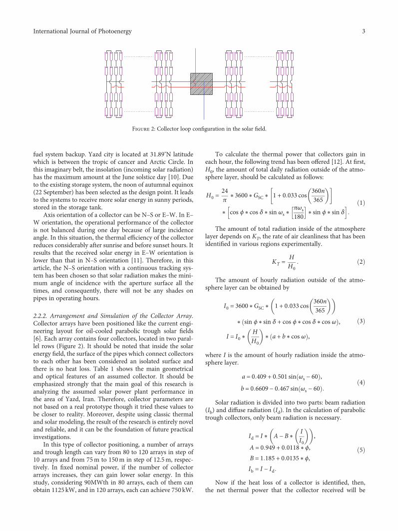
2.2.2. Arrangement and Simulation of the Collector Array.Collector arrays have been positioned like the current engi-neering layout for oil-cooled parabolic trough solar fields[6]. Each array contains four collectors, located in two paral-lel rows (Figure 2). It should be noted that inside the solarenergy field, the surface of the pipes which connect collectorsto each other has been considered an isolated surface andthere is no heat loss. Table 1 shows the main geometricaland optical features of an assumed collector. It should beemphasized strongly that the main goal of this research isanalyzing the assumed solar power plant performance inthe area of Yazd, Iran. Therefore, collector parameters arenot based on a real prototype though it tried these values tobe closer to reality. Moreover, despite using classic thermaland solar modeling, the result of the research is entirely noveland reliable, and it can be the foundation of future practicalinvestigations.
In this type of collector positioning, a number of arraysand trough length can vary from 80 to 120 arrays in step of10 arrays and from 75m to 150m in step of 12.5m, respec-tively. In fixed nominal power, if the number of collectorarrays increases, they can gain lower solar energy. In thisstudy, considering 90MWth in 80 arrays, each of them canobtain 1125 kW, and in 120 arrays, each can achieve 750 kW.
To calculate the thermal power that collectors gain ineach hour, the following trend has been offered [12]. At first,H0, the amount of total daily radiation outside of the atmo-sphere layer, should be calculated as follows:
H0 =24π
∗ 3600∗GSC ∗ 1 + 0 033 cos 360n365
∗ cos ϕ∗ cos δ∗ sin ωs ∗πωs180 ∗ sin ϕ∗ sin δ
1
The amount of total radiation inside of the atmospherelayer depends on KT, the rate of air cleanliness that has beenidentified in various regions experimentally.
KT = HH0
2
The amount of hourly radiation outside of the atmo-sphere layer can be obtained by
I0 = 3600∗GSC ∗ 1 + 0 033 cos 360n365
∗ sin ϕ∗ sin δ + cos ϕ∗ cos δ∗ cos ω ,
I = I0 ∗HH0
∗ a + b∗ cos ω ,
3
where I is the amount of hourly radiation inside the atmo-sphere layer.
a = 0 409 + 0 501 sin ωs − 60 ,b = 0 6609 − 0 467 sin ωs − 60
4
Solar radiation is divided into two parts: beam radiation(Ib) and diffuse radiation (Id). In the calculation of parabolictrough collectors, only beam radiation is necessary.
Id = I ∗ A − B∗II0
,A = 0 949 + 0 0118∗ϕ,B = 1 185 + 0 0135∗ϕ,Ib = I − Id
5
Now if the heat loss of a collector is identified, then,the net thermal power that the collector received will be
Figure 2: Collector loop configuration in the solar field.
3International Journal of Photoenergy
specified. Heat loss consists of convection and radiationparts [12].
qu = Fr ∗ w − do ∗L∗ s −UL
cT f i − Ta
= m∗ cpoil ∗ T fo − T f i ,
s = Ib ∗w
w − do∗ ηopt,
6
where qu is the useful thermal power that the collectorreceives by beam radiation. The heat lost and efficiency canbe calculated as follows:
qlL= hp−c ∗ Tpm − Tc ∗πdo
+σπ T4
pm − T4c do
1/εp + do/dci 1/εc − 1 ,
qlL= hwπdco ∗ Tc − Ta + σπdcoεc ∗ T4
c − T4sky ,
qlL= UL
L∗πdo ∗ Tpm − Ta ,
η = quIb ∗w∗L
7
By selection of the outlet temperature of oil in an array(Tfo), average temperature of the receiver tube (pipe) surface(Tpm), and the total heat transfer factor (UL) as initialassumptions and then running a trial-and-error algorithm,qu will be obtained [12].
An operational temperature for Theminol VP-1 should becontrolled in the range between 12 and 400°C. The lowertemperature causes oil freezing as well as the higher temper-ature of oil results in chemical reaction.
2.2.3. Effect of Mass Flow Values.Mass flow greatly affects thereceived solar thermal power. Because the design point hasnot been chosen among completely sunny days (June sol-stice), therefore, mass flow must not be near the maximumcapacity of the system so that it can increase in sunny periodsto keep oil temperature lower than 400°C. On the other hand,this mass flow should not be meager because, at first, it causesa reduction of thermal efficiency noticeably, and then, thedimensions of the solar field will rise unreasonably to supplysufficient solar thermal power.
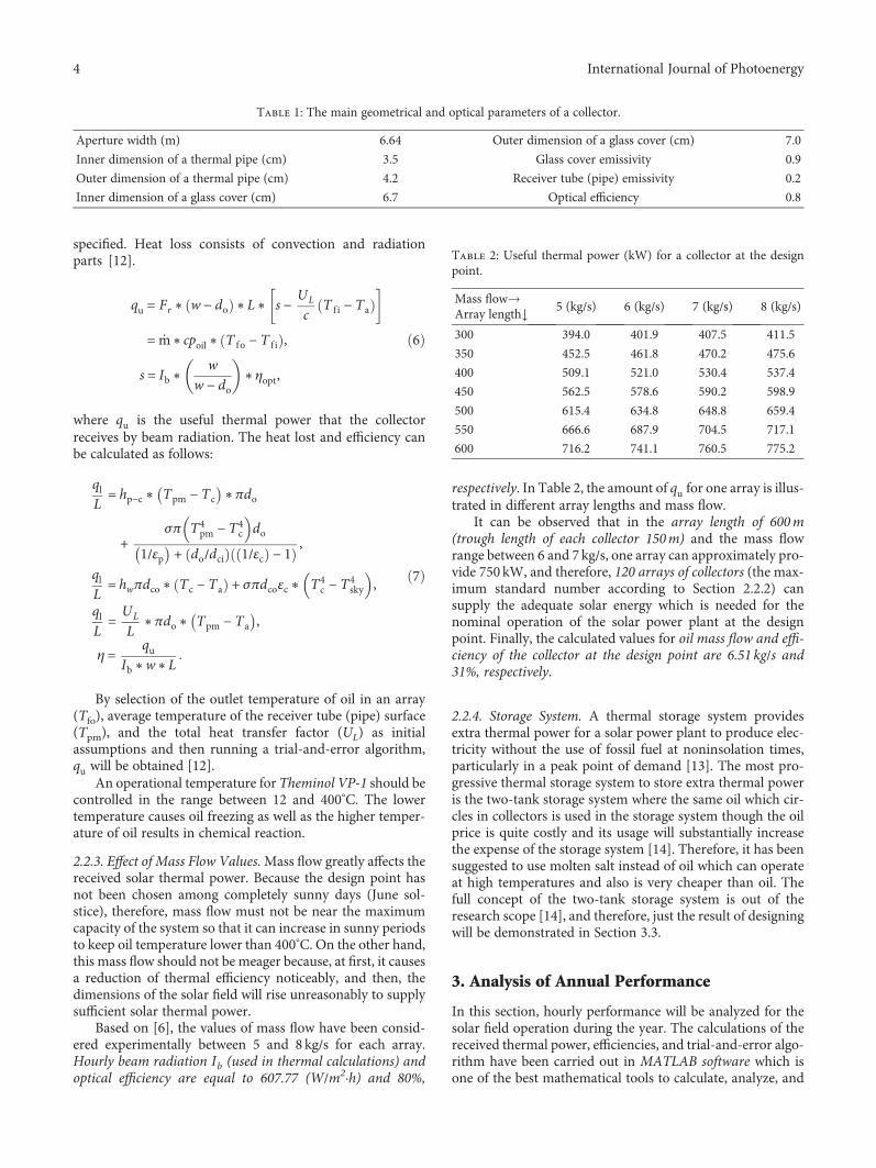
Based on [6], the values of mass flow have been consid-ered experimentally between 5 and 8 kg/s for each array.Hourly beam radiation Ib (used in thermal calculations) andoptical efficiency are equal to 607.77 (W/m2·h) and 80%,
respectively. In Table 2, the amount of qu for one array is illus-trated in different array lengths and mass flow.
It can be observed that in the array length of 600m(trough length of each collector 150m) and the mass flowrange between 6 and 7 kg/s, one array can approximately pro-vide 750 kW, and therefore, 120 arrays of collectors (the max-imum standard number according to Section 2.2.2) cansupply the adequate solar energy which is needed for thenominal operation of the solar power plant at the designpoint. Finally, the calculated values for oil mass flow and effi-ciency of the collector at the design point are 6.51 kg/s and31%, respectively.
2.2.4. Storage System. A thermal storage system providesextra thermal power for a solar power plant to produce elec-tricity without the use of fossil fuel at noninsolation times,particularly in a peak point of demand [13]. The most pro-gressive thermal storage system to store extra thermal poweris the two-tank storage system where the same oil which cir-cles in collectors is used in the storage system though the oilprice is quite costly and its usage will substantially increasethe expense of the storage system [14]. Therefore, it has beensuggested to use molten salt instead of oil which can operateat high temperatures and also is very cheaper than oil. Thefull concept of the two-tank storage system is out of theresearch scope [14], and therefore, just the result of designingwill be demonstrated in Section 3.3.
3. Analysis of Annual Performance
In this section, hourly performance will be analyzed for thesolar field operation during the year. The calculations of thereceived thermal power, efficiencies, and trial-and-error algo-rithm have been carried out in MATLAB software which isone of the best mathematical tools to calculate, analyze, and
Table 1: The main geometrical and optical parameters of a collector.
Aperture width (m) 6.64 Outer dimension of a glass cover (cm) 7.0
Inner dimension of a thermal pipe (cm) 3.5 Glass cover emissivity 0.9
Outer dimension of a thermal pipe (cm) 4.2 Receiver tube (pipe) emissivity 0.2
Inner dimension of a glass cover (cm) 6.7 Optical efficiency 0.8
Table 2: Useful thermal power (kW) for a collector at the designpoint.
Mass flow→Array length↓
5 (kg/s) 6 (kg/s) 7 (kg/s) 8 (kg/s)
300 394.0 401.9 407.5 411.5
350 452.5 461.8 470.2 475.6
400 509.1 521.0 530.4 537.4
450 562.5 578.6 590.2 598.9
500 615.4 634.8 648.8 659.4
550 666.6 687.9 704.5 717.1
600 716.2 741.1 760.5 775.2
4 International Journal of Photoenergy
simulate the engineering project. The following result will berepresented for each month individually:
(1) The amount of useful thermal power per array whichwill be demonstrated in different hour ranges in full-load and part-load conditions
(2) Efficiency of array
(3) Mass flow fluctuations, especially in sunny periods,that must be increased to keep the temperature ofoil in all allowable ranges
3.1. Solar Hour. Undoubtedly, solar radiation depends on thelocation of the sun in the sky during the day. The solar houris introduced to make the analysis more sensible. In this def-inition, solar noon is a special time in the middle of sunriseand sunset, considered as 12:00 in a solar time scale whereasthe local time scale is not 12:00 exactly.
3.2. Daily Analysis of the Solar Field. At first, it is assumedthat the solar field begins to operate when it can supply, atleast, 25% of Rankine cycle need (187.5 kW for each array).The analysis of a power plant is based on an average of hourlysolar radiation. At first, the hourly solar radiation outside of
the atmosphere has been calculated, and then, by consideringthe rate of air cleanliness, the hourly average radiation insidethe atmosphere has been computed. The rates of air cleanli-ness are constant coefficient which was gained according toweather statistic data in the last 20 years [15].
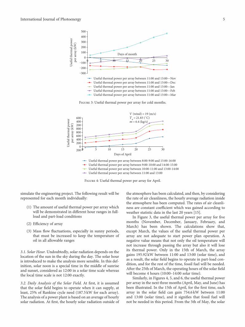
In Figure 3, the useful thermal power per array for fivemonths (November, December, January, February, andMarch) has been shown. The calculations show that,except March, the values of the useful thermal power perarray are not adequate to start power plan operation. Anegative value means that not only the oil temperature willnot increase through passing the array but also it will loseits thermal power. Only in the 15th of March, the arraygains 195.92 kW between 11:00 and 13:00 (solar time), andas a result, the solar field begins to operate in part-load con-dition, and for the rest of the time, fossil fuel will be needed.After the 25th of March, the operating hours of the solar fieldwill become 4 hours (10:00–14:00 solar time).
Similarly, in Figures 4, 5, and 6, the useful thermal powerper array in the next three months (April, May, and June) hasbeen illustrated. In the 15th of April, for the first time, eacharray in the solar field can gain 754.6 kW between 11:00and 13:00 (solar time), and it signifies that fossil fuel willnot be needed in this period. From the 5th of May, the solar
500400300200100
0‒100‒200‒300
Use
ful t
herm
al p
ower
per a
rray
(kW
)
Days of month
0 5 10 15 20 25 30
Useful thermal power per array between 11:00 and 13:00—NovUseful thermal power per array between 11:00 and 13:00—DecUseful thermal power per array between 11:00 and 13:00—JanUseful thermal power per array between 11:00 and 13:00—FebUseful thermal power per array between 11:00 and 13:00—Mar
Figure 3: Useful thermal power per array for cold months.
600400200000800600400200
0200
Use
ful t
herm
al p
ower
per a
rray
(kW
)
0 5 10 15 20 25 30Days of April
V (wind) = 19 (m/s)Ta = 21.83 (˚C)m = 6.4 (kg/s)
Useful thermal power per array between 8:00-9:00 and 15:00-16:00Useful thermal power per array between 9:00-10:00 and 14:00-15:00Useful thermal power per array between 10:00-11:00 and 13:00-14:00Useful thermal power per array between 11:00 and 13:00
Figure 4: Useful thermal power per array for April.
5International Journal of Photoenergy
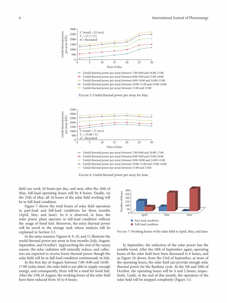
field can work 10 hours per day, and next, after the 10th ofMay, full-load operating hours will be 8 hours. Finally, onthe 25th of May, all 10 hours of the solar field working willbe in full-load condition.
Figure 7 shows the total hours of solar field operationin part-load and full-load conditions for three months(April, May, and June). As it is observed, in June, thesolar power plant operates in full-load condition withoutthe usage of fossil fuel. Moreover, the extra thermal powerwill be saved in the storage tank whose analysis will beexplained in Section 3.3.
In the same manner, Figures 8, 9, 10, and 11 illustrate theuseful thermal power per array in four months (July, August,September, and October). Approaching the end of the sunnyseason, the solar radiation will naturally reduce, and collec-tors are expected to receive lower thermal power though thesolar field will be in full-load condition continuously in July.
In the first day of August, between 7:00–8:00 and 16:00–17:00 (solar time), the solar field is not able to supply enoughenergy, and consequently, there will be a need for fossil fuel.After the 15th of August, the working hours of the solar fieldhave been reduced from 10 to 8 hours.
In September, the reduction of the solar power has thenotable trend. After the 10th of September, again, operatinghours of the solar field have been decreased to 6 hours, andas Figure 10 shows, from the 23rd of September, at none ofthe operating hours, the solar field can provide enough solarthermal power for the Rankine cycle. At the 5th and 20th ofOctober, the operating hours will be 4 and 2 hours, respec-tively. Lastly, at the end of this month, the operation of thesolar field will be stopped completely (Figure 11).
30002500200015001000
5000
Use
ful t
herm
al p
ower
per a
rray
(kW
)0 5 10 15 20 25 30
Days of May
V (wind) = 22 (m/s)Ta = 27.7 (˚C)m = �uctuated
Useful thermal power per array between 7:00-8:00 and 16:00-17:00Useful thermal power per array between 8:00-9:00 and 15:00-16:00Useful thermal power per array between 9:00-10:00 and 14:00-15:00Useful thermal power per array between 10:00-11:00 and 13:00-14:00Useful thermal power per array between 11:00 and 13:00
Figure 5: Useful thermal power per array for May.
350030002500200015001000
5000
Use
ful t
herm
al p
ower
per a
rray
(kW
)
0 5 10 15 20 25 30Days of June
V (wind) = 21 (m/s)Ta = 33.08 (˚C)m = �uctuated
Useful thermal power per array between 7:00-8:00 and 16:00-17:00Useful thermal power per array between 8:00-9:00 and 15:00-16:00Useful thermal power per array between 9:00-10:00 and 14:00-15:00Useful thermal power per array between 10:00-11:00 and 13:00-14:00Useful thermal power per array between 11:00 and 13:00
Figure 6: Useful thermal power per array for June.
300250200150100
500N
umbe
r of h
ours
April May June
Part-load conditionFull-load condition
136
56 58
244
0
300
Figure 7: Working hours of the solar field in April, May, and June.
6 International Journal of Photoenergy
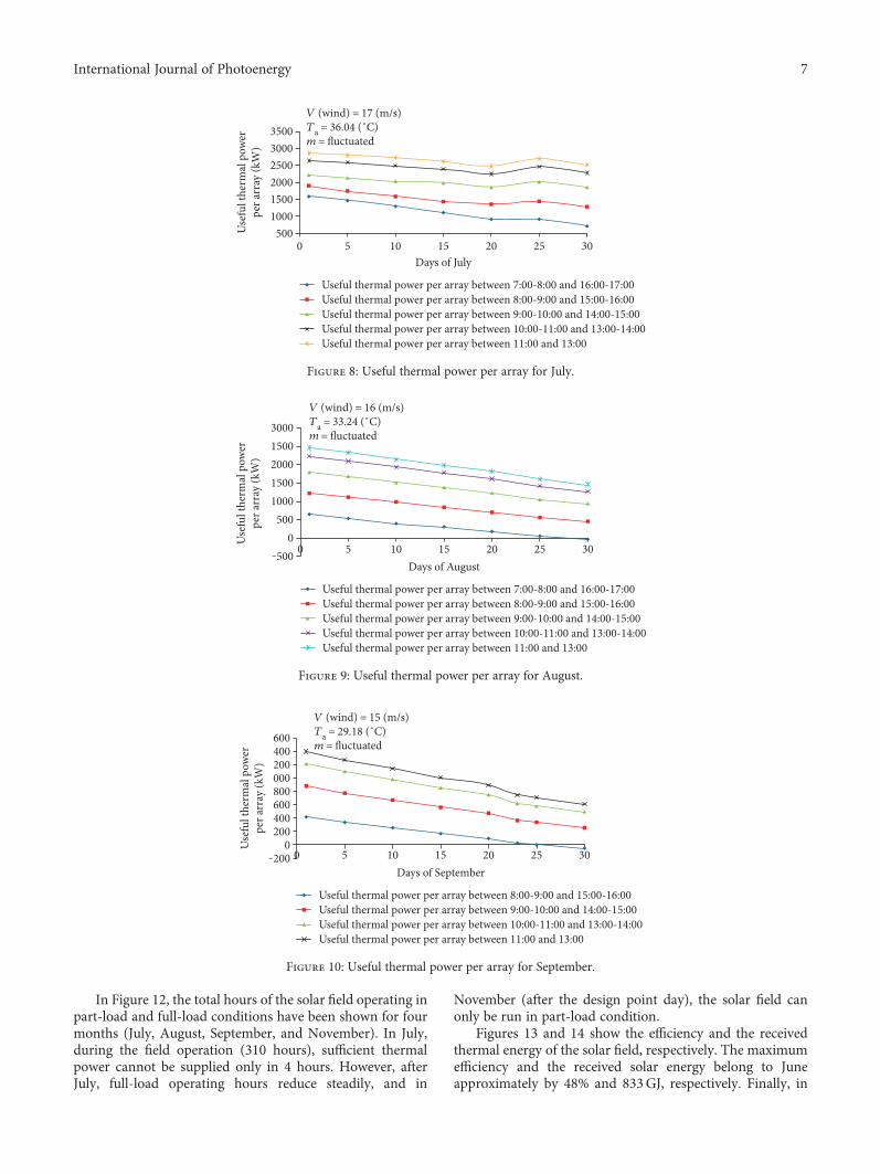
In Figure 12, the total hours of the solar field operating inpart-load and full-load conditions have been shown for fourmonths (July, August, September, and November). In July,during the field operation (310 hours), sufficient thermalpower cannot be supplied only in 4 hours. However, afterJuly, full-load operating hours reduce steadily, and in
November (after the design point day), the solar field canonly be run in part-load condition.
Figures 13 and 14 show the efficiency and the receivedthermal energy of the solar field, respectively. The maximumefficiency and the received solar energy belong to Juneapproximately by 48% and 833GJ, respectively. Finally, in
350030002500200015001000
500Use
ful t
herm
al p
ower
per a
rray
(kW
)0 5 10 15 20 25 30
Days of July
V (wind) = 17 (m/s)Ta = 36.04 (˚C)m = �uctuated
Useful thermal power per array between 7:00-8:00 and 16:00-17:00Useful thermal power per array between 8:00-9:00 and 15:00-16:00Useful thermal power per array between 9:00-10:00 and 14:00-15:00Useful thermal power per array between 10:00-11:00 and 13:00-14:00Useful thermal power per array between 11:00 and 13:00
Figure 8: Useful thermal power per array for July.
30001500200015001000
500
‒5000U
sefu
l the
rmal
pow
erpe
r arr
ay (k
W)
0 5 10 15 20 25 30Days of August
V (wind) = 16 (m/s)Ta = 33.24 (˚C)m = �uctuated
Useful thermal power per array between 7:00-8:00 and 16:00-17:00Useful thermal power per array between 8:00-9:00 and 15:00-16:00Useful thermal power per array between 9:00-10:00 and 14:00-15:00Useful thermal power per array between 10:00-11:00 and 13:00-14:00Useful thermal power per array between 11:00 and 13:00
Figure 9: Useful thermal power per array for August.
600400200000800600400200
0‒200
Use
ful t
herm
al p
ower
per a
rray
(kW
)
0 5 10 15 20 25 30Days of September
V (wind) = 15 (m/s)Ta = 29.18 (˚C)m = �uctuated
Useful thermal power per array between 8:00-9:00 and 15:00-16:00Useful thermal power per array between 9:00-10:00 and 14:00-15:00Useful thermal power per array between 10:00-11:00 and 13:00-14:00Useful thermal power per array between 11:00 and 13:00
Figure 10: Useful thermal power per array for September.
7International Journal of Photoenergy
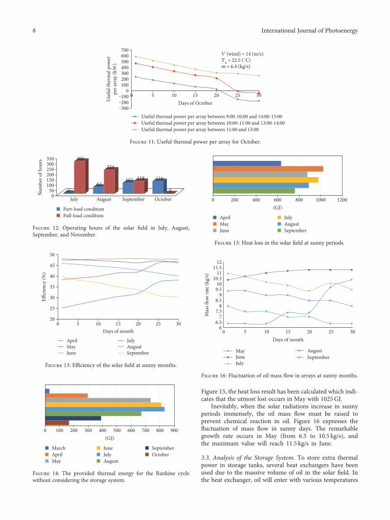
Figure 15, the heat loss result has been calculated which indi-cates that the utmost lost occurs in May with 1025GJ.
Inevitably, when the solar radiations increase in sunnyperiods immensely, the oil mass flow must be raised toprevent chemical reaction in oil. Figure 16 expresses thefluctuation of mass flow in sunny days. The remarkablegrowth rate occurs in May (from 6.5 to 10.5 kg/s), andthe maximum value will reach 11.5 kg/s in June.
3.3. Analysis of the Storage System. To store extra thermalpower in storage tanks, several heat exchangers have beenused due to the massive volume of oil in the solar field. Inthe heat exchanger, oil will enter with various temperatures
Useful thermal power per array between 9:00-10:00 and 14:00-15:00Useful thermal power per array between 10:00-11:00 and 13:00-14:00Useful thermal power per array between 11:00 and 13:00
700600500400300200100
0‒100‒200‒300
Use
ful t
herm
al p
ower
per a
rray
(kW
)
0 5 10 15 20 25 30Days of October
V (wind) = 14 (m/s)Ta = 22.5 (˚C)m = 6.4 (kg/s)
Figure 11: Useful thermal power per array for October.
350300250200150100
500N
umbe
r of h
ours
July August September October
Part-load conditionFull-load condition
4
306
62
224
102 118 116
0
Figure 12: Operating hours of the solar field in July, August,September, and November.
50
45
40
35
30
25
20
E�ci
ency
(%)
0 5 10 15 20 25 30Days of month
AprilMayJune
JulyAugustSeptember
Figure 13: Efficiency of the solar field at sunny months.
0 100 200 300 400 500 600 700 800 900(GJ)
SeptemberOctober
JuneJulyAugust
MarchAprilMay
Figure 14: The provided thermal energy for the Rankine cyclewithout considering the storage system.
0 200 400 600 800 1000 1200(GJ)
JulyAugustSeptember
AprilMayJune
Figure 15: Heat loss in the solar field at sunny periods.
12
MayJuneJuly
AugustSeptember
Mas
s �ow
rate
(kg/
s)
11.511
10.510
9.59
8.58
7.57
6.56
0 5 10 15Days of month
20 25 30
Figure 16: Fluctuation of oil mass flow in arrays at sunny months.
8 International Journal of Photoenergy
but should exit in 290°C (as the assumption of oil inlet tem-perature in the array). Molten salt (Cp,salt = 1 6 kJ/kg ⋅ K&ρsalt = 1750 kg/m3) from the cold tank pipes whose tempera-ture is 285°C enters the heat exchanger, and with adjustmentof its mass flow, oil outlet temperature will be set to 290°C.
The storage tank has been designed based on the Junesolstice day wherein the maximum heat power is received.Table 3 shows the mass flows of molten salt whichshould pass through all heat exchangers in that specialday which guarantee that the outlet oil temperature wouldbe 290°C. The calculation of the heat exchanger operationindicates that the capacity of each storage tank should be1850.3 m3(3,237,992 kg needed salt) to store the entire extrathermal power.
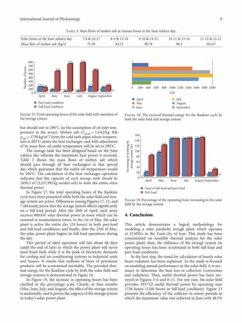
In Figure 17, the total operating hours of the Rankinecycle have been presented while both the solar field and stor-age system are active. Differences among Figures 17, 12, and7 obviously prove that the storage system affects significantlyon a full-load period. After the 20th of April, each arrayreceives 800 kW solar thermal power at noon which can berestored at noninsolation times. In the 1st of May, the solarplant is active the entire day (24 hours) in both part-loadand full-load conditions, and finally, after the 25th of May,the solar power plant begins its full-load operations duringthe day.
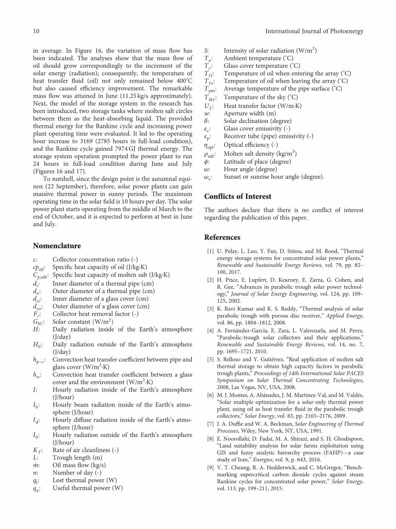
This period of ideal operation will last about 68 days(until the end of July) in which the power plant will neverneed fossil fuels while it is the peak of electricity demandsfor cooling and air conditioning systems in industrial unitsand houses. It results that millions of liters of petroleumproducts will be economized inevitably. The provided ther-mal energy for the Rankine cycle by both the solar field andstorage systems is demonstrated in Figure 18.
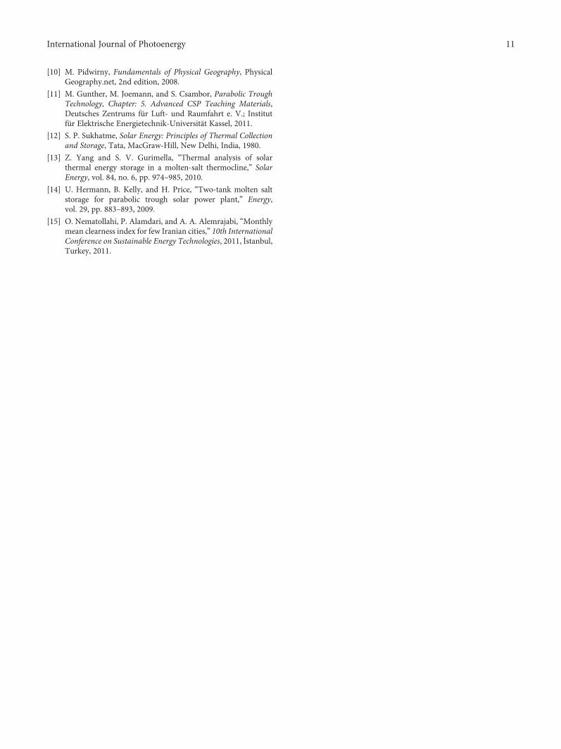
In Figure 19, the increase in operating hours has beenclarified in the percentage scale. Clearly, in four months(May, June, July, and August), the effect of the storage systemis undeniable, and it proves the urgency of the storage systemin today’s solar power plant.
4. Conclusion
This article demonstrates a logical methodology formodeling a solar parabolic trough plant which operatesat 25MWe in the Yazd city of Iran. This study has beenconcentrated on monthly thermal analysis for the solarpower plant; then, the influence of the storage system onoperating hours has been scrutinized in both full-load andpart-load conditions.
In the first step, the trend for calculation of hourly solarbeam radiation has been explained. As the study is focusedon modeling annual performance in the solar field, it is nec-essary to determine the heat loss in collectors (convectionand radiation). Then, useful thermal power has been sur-veyed in Figures 3–6 and 8–11. For one year, the solar fieldprovides 3937GJ useful thermal power by operating near1726 hours (1248 hours in full-load condition). Figure 13presents the efficiency of the collector in sunny periods inwhich the maximum value was achieved in June with 48.5%
Table 3: Mass flows of molten salt at various hours at the June solstice day.
Solar hours at the June solstice day 7-8 & 16-17 8-9 & 15-16 9-10 & 14-15 10-11 & 13-14 11-12 & 12-13
Mass flow of molten salt (kg/s) 75.39 83.72 90.78 98.3 101.67
800700600500400300200200
0April
12210043 0 0
122 97 148
526
720 744
547
May June July August September
Num
ber o
f hou
rs
Part-load conditionFull-load condition
Figure 17: Total operating hours of the solar field with operation ofthe storage system.
(GJ)0 200 400 600 800 1000 1200 1400 1600 1800 2000
JulyAugustSeptember
AprilMayJune
Figure 18: The received thermal energy for the Rankine cycle byboth the solar field and storage system.
160140120100
80604020
0April
Incr
easin
g of
wor
king
by
stora
ge sy
stem
(%)
15
7888
116
140140 140 140143 144
1125
May June July August September
Total of full-load and part-loadFull-load
Figure 19: Percentage of the operating hour increasing in the solarfield by the storage system.
9International Journal of Photoenergy
in average. In Figure 16, the variation of mass flow hasbeen indicated. The analyses show that the mass flow ofoil should grow correspondingly to the increment of thesolar energy (radiation); consequently, the temperature ofheat transfer fluid (oil) not only remained below 400°Cbut also caused efficiency improvement. The remarkablemass flow was attained in June (11.25 kg/s approximately).Next, the model of the storage system in the research hasbeen introduced, two storage tanks where molten salt circlesbetween them as the heat-absorbing liquid. The providedthermal energy for the Rankine cycle and increasing powerplant operating time were evaluated. It led to the operatinghour increase to 3169 (2785 hours in full-load condition),and the Rankine cycle gained 7974GJ thermal energy. Thestorage system operation prompted the power plant to run24 hours in full-load condition during June and July(Figures 16 and 17).
To nutshell, since the design point is the autumnal equi-nox (22 September), therefore, solar power plants can gainmassive thermal power in sunny periods. The maximumoperating time in the solar field is 10 hours per day. The solarpower plant starts operating from the middle of March to theend of October, and it is expected to perform at best in Juneand July.
Nomenclature
c: Collector concentration ratio (-)cpoil: Specific heat capacity of oil (J/kg·K)Cp,salt: Specific heat capacity of molten salt (J/kg·K)di: Inner diameter of a thermal pipe (cm)do: Outer diameter of a thermal pipe (cm)dci: Inner diameter of a glass cover (cm)dco: Outer diameter of a glass cover (cm)Fr : Collector heat removal factor (-)GSC: Solar constant W/m2
H: Daily radiation inside of the Earth’s atmosphere(J/day)
H0: Daily radiation outside of the Earth’s atmosphere(J/day)
hp−c: Convection heat transfer coefficient between pipe andglass cover (W/m2·K)
hw: Convection heat transfer coefficient between a glasscover and the environment (W/m2·K)
I: Hourly radiation inside of the Earth’s atmosphere(J/hour)
Ib: Hourly beam radiation inside of the Earth’s atmo-sphere (J/hour)
Id: Hourly diffuse radiation inside of the Earth’s atmo-sphere (J/hour)
I0: Hourly radiation outside of the Earth’s atmosphere(J/hour)
KT : Rate of air cleanliness (-)L: Trough length (m)m: Oil mass flow (kg/s)n: Number of day (-)ql: Lost thermal power (W)qu: Useful thermal power (W)
S: Intensity of solar radiation (W/m2)Ta: Ambient temperature (°C)Tc: Glass cover temperature (°C)T f i: Temperature of oil when entering the array (°C)T fo: Temperature of oil when leaving the array (°C)Tpm: Average temperature of the pipe surface (°C)Tsky: Temperature of the sky (°C)UL: Heat transfer factor (W/m·K)w: Aperture width (m)δ: Solar declination (degree)εc: Glass cover emissivity (-)εp: Receiver tube (pipe) emissivity (-)ηopt: Optical efficiency (-)ρsalt: Molten salt density (kg/m3)ϕ: Latitude of place (degree)ω: Hour angle (degree)ωs: Sunset or sunrise hour angle (degree).
Conflicts of Interest
The authors declare that there is no conflict of interestregarding the publication of this paper.
References
[1] U. Pelay, L. Luo, Y. Fan, D. Stitou, and M. Rood, “Thermalenergy storage systems for concentrated solar power plants,”Renewable and Sustainable Energy Reviews, vol. 79, pp. 82–100, 2017.
[2] H. Price, E. Lupfert, D. Kearney, E. Zarza, G. Cohen, andR. Gee, “Advances in parabolic trough solar power technol-ogy,” Journal of Solar Energy Engineering, vol. 124, pp. 109–125, 2002.
[3] K. Ravi Kumar and K. S. Reddy, “Thermal analysis of solarparabolic trough with porous disc receiver,” Applied Energy,vol. 86, pp. 1804–1812, 2008.
[4] A. Fernández-García, E. Zara, L. Valenzuela, and M. Perez,“Parabolic-trough solar collectors and their applications,”Renewable and Sustainable Energy Reviews, vol. 14, no. 7,pp. 1695–1721, 2010.
[5] S. Relloso and Y. Gutiérrez, “Real application of molten saltthermal storage to obtain high capacity factors in parabolictrough plants,” Proceedings of 14th International Solar PACESSymposium on Solar Thermal Concentrating Technologies,2008, Las Vegas, NV, USA, 2008.
[6] M. J. Montes, A. Abánades, J. M. Martinez-Val, andM. Valdés,“Solar multiple optimization for a solar-only thermal powerplant, using oil as heat transfer fluid in the parabolic troughcollectors,” Solar Energy, vol. 83, pp. 2165–2176, 2009.
[7] J. A. Duffie and W. A. Beckman, Solar Engineering of ThermalProcesses, Wiley, New York, NY, USA, 1991.
[8] E. Noorollahi, D. Fadai, M. A. Shirazi, and S. H. Ghodispoor,“Land suitability analysis for solar farms exploitation usingGIS and fuzzy analytic hierarchy process (FAHP)—a casestudy of Iran,” Energies, vol. 9, p. 643, 2016.
[9] V. T. Cheang, R. A. Hedderwick, and C. McGregor, “Bench-marking supercritical carbon dioxide cycles against steamRankine cycles for concentrated solar power,” Solar Energy,vol. 113, pp. 199–211, 2015.
10 International Journal of Photoenergy
[10] M. Pidwirny, Fundamentals of Physical Geography, PhysicalGeography.net, 2nd edition, 2008.
[11] M. Gunther, M. Joemann, and S. Csambor, Parabolic TroughTechnology, Chapter: 5. Advanced CSP Teaching Materials,Deutsches Zentrums für Luft- und Raumfahrt e. V.; Institutfür Elektrische Energietechnik-Universität Kassel, 2011.
[12] S. P. Sukhatme, Solar Energy: Principles of Thermal Collectionand Storage, Tata, MacGraw-Hill, New Delhi, India, 1980.
[13] Z. Yang and S. V. Gurimella, “Thermal analysis of solarthermal energy storage in a molten-salt thermocline,” SolarEnergy, vol. 84, no. 6, pp. 974–985, 2010.
[14] U. Hermann, B. Kelly, and H. Price, “Two-tank molten saltstorage for parabolic trough solar power plant,” Energy,vol. 29, pp. 883–893, 2009.
[15] O. Nematollahi, P. Alamdari, and A. A. Alemrajabi, “Monthlymean clearness index for few Iranian cities,” 10th InternationalConference on Sustainable Energy Technologies, 2011, İstanbul,Turkey, 2011.
11International Journal of Photoenergy

Submit your manuscripts athttps://www.hindawi.com
Hindawi Publishing Corporationhttp://www.hindawi.com Volume 2014
Inorganic ChemistryInternational Journal of
Hindawi Publishing Corporation http://www.hindawi.com Volume 201
International Journal ofInternational Journal ofPhotoenergy
Hindawi Publishing Corporationhttp://www.hindawi.com Volume 2014
Carbohydrate Chemistry
International Journal ofInternational Journal of
Hindawi Publishing Corporationhttp://www.hindawi.com Volume 2014
Journal of
Chemistry
Hindawi Publishing Corporationhttp://www.hindawi.com Volume 2014
Advances in
Physical Chemistry
Hindawi Publishing Corporationhttp://www.hindawi.com
Analytical Methods in Chemistry
Journal of
Volume 2014
Bioinorganic Chemistry and ApplicationsHindawi Publishing Corporationhttp://www.hindawi.com Volume 2014
SpectroscopyInternational Journal of
Hindawi Publishing Corporationhttp://www.hindawi.com Volume 2014
The Scientific World JournalHindawi Publishing Corporation http://www.hindawi.com Volume 2014
Medicinal ChemistryInternational Journal of
Hindawi Publishing Corporationhttp://www.hindawi.com Volume 2014
Chromatography Research International
Hindawi Publishing Corporationhttp://www.hindawi.com Volume 2014
Applied ChemistryJournal of
Hindawi Publishing Corporationhttp://www.hindawi.com Volume 2014
Hindawi Publishing Corporationhttp://www.hindawi.com Volume 2014
Theoretical ChemistryJournal of
Hindawi Publishing Corporationhttp://www.hindawi.com Volume 2014
Journal of
Spectroscopy
Analytical ChemistryInternational Journal of
Hindawi Publishing Corporationhttp://www.hindawi.com Volume 2014
Journal of
Hindawi Publishing Corporationhttp://www.hindawi.com Volume 2014
Quantum Chemistry
Hindawi Publishing Corporationhttp://www.hindawi.com Volume 2014
Organic Chemistry International
ElectrochemistryInternational Journal of
Hindawi Publishing Corporation http://www.hindawi.com Volume 2014
Hindawi Publishing Corporationhttp://www.hindawi.com Volume 2014
CatalystsJournal of